EP0208062A2 - Container for a number of disc-shaped objects, and container part thereof - Google Patents
Container for a number of disc-shaped objects, and container part thereof Download PDFInfo
- Publication number
- EP0208062A2 EP0208062A2 EP86104348A EP86104348A EP0208062A2 EP 0208062 A2 EP0208062 A2 EP 0208062A2 EP 86104348 A EP86104348 A EP 86104348A EP 86104348 A EP86104348 A EP 86104348A EP 0208062 A2 EP0208062 A2 EP 0208062A2
- Authority
- EP
- European Patent Office
- Prior art keywords
- parts
- base body
- container according
- container
- shape
- Prior art date
- Legal status (The legal status is an assumption and is not a legal conclusion. Google has not performed a legal analysis and makes no representation as to the accuracy of the status listed.)
- Granted
Links
Images


Classifications
-
- G—PHYSICS
- G11—INFORMATION STORAGE
- G11B—INFORMATION STORAGE BASED ON RELATIVE MOVEMENT BETWEEN RECORD CARRIER AND TRANSDUCER
- G11B33/00—Constructional parts, details or accessories not provided for in the other groups of this subclass
- G11B33/02—Cabinets; Cases; Stands; Disposition of apparatus therein or thereon
- G11B33/04—Cabinets; Cases; Stands; Disposition of apparatus therein or thereon modified to store record carriers
- G11B33/0405—Cabinets; Cases; Stands; Disposition of apparatus therein or thereon modified to store record carriers for storing discs
- G11B33/0433—Multiple disc containers
- G11B33/0444—Multiple disc containers for discs without cartridge
Definitions
- the invention relates to a container for a plurality of disk-shaped objects, in particular record carriers, consisting of a base body open on at least two sides with a plurality of receiving grooves for the objects and at least one cover part and releasable locking devices provided between the base body and cover part (s), and a container part thereof.
- Such a container for storage disks which consists of a closable by means of a lid box, in which a plurality of mutually parallel grooves are mounted, the inside width corresponds to the width of a disk and which run according to the dimensions of the disk, and has at least two thin, elastically deformable projections which are separate from one another and project into the interior of the container and extend transversely to the direction of the grooves over the entire area in which grooves are present, and which in the case of data carrier disks inserted into the container on at least two in the circumferential direction against one another cross-stitched areas at the same fit (DE-OS 34 29 244).
- the plates can be protected against contamination and mechanical damage.
- the grooves in this container keep the plates at a distance so that they cannot touch during transport of the container. Due to the elastically deformable projections, the plates are pressed into the grooves and thus fixed in their position.
- the projections are formed in the known container as relatively low-material slats, the elasticity of which quickly subsides. In addition, the thin slats can easily break off, so that the plates are no longer adequately protected.
- the box of this container is overall as high as the plates to be transported with it. This results in the disadvantage that the plates can only be inserted into the box with difficulty. It also makes the box difficult to clean.
- the known container has a removable bottom. This makes the container complex as a whole, since three differently constructed and separately manufactured parts are required with the box, lid and base.
- PCT-OS WO 86100746 is a container for thin objects, in particular FlexyDisks® (0 registered trademark of BASF Aktiengesellschaft shaft) is known, two externally identical container halves forming a container which is closed on all sides and provided with receiving elements for the FlexyDisks.
- the receiving elements are formed by L-shaped elements with grooves for the edges of a FlexyDisk, the elements being arranged in each half of the container. This means that the distance between the individual FlexyDisks is larger in each half than if each of the halves formed a single container.
- the halves are articulated together.
- This container is a purely archive container and, due to its many individual parts, is also difficult to manufacture.
- Disk-shaped objects within the scope of the present invention can be any disk body such as, e.g. Printed circuits, wafers for integrated circuits, etc., or any type of disk or plate-shaped recording medium, such as magnetic disks, optical, magneto-optical, or electrical storage disks for storing any information, in analog, digital or pictorial form.
- Printed circuits, wafers for integrated circuits, etc. or any type of disk or plate-shaped recording medium, such as magnetic disks, optical, magneto-optical, or electrical storage disks for storing any information, in analog, digital or pictorial form.
- the purpose of a container according to the genus of the present invention is explained below using data carrier disks.
- disks can be, for example, magnetic storage disks for EDP systems which have a coated metal body.
- the disks can also be other data carriers having a coated, rigid base body, such as so-called digital magnetic disks.
- the layer available for the storage of data is very sensitive. The plates must therefore be handled very carefully in the manufacturing plant, during manufacture, during transport from the manufacturing plant to the consumer, but also later. It is particularly important to ensure that the sensitive coating is not damaged.
- the object is achieved with a container of the type defined in the introduction if the base body consists of two composable, essentially identical parts and two further, essentially identical cover parts are provided, each cover part at least partially covering at least one of the openings of the base body and the locking devices are provided at least on a cover part, by means of which the two parts of the base body can be releasably locked together.
- Circular disks can be gripped and gripped by their outer diameters and can be lifted out quickly and without risk of damage or contamination.
- the container according to the invention consists of a total of four parts. However, since they are essentially identical or even identical in pairs, only two differently designed parts need to be produced. The manufacturing effort is therefore low, and only two different parts need to be stored.
- the container can be easily cleaned if the body parts only occupy about half the height of the container and are therefore easily accessible from the inside.
- the cover parts are unproblematic for cleaning, since they can be made accessible from all sides.
- Another advantage of this container is that in the event of a part being damaged, it is easily interchangeable due to the essentially paired identity.
- the cover parts have an L-shape in the side elevation, and each arm of the L-shape comprises one side of the base body in the side elevation.
- each arm of the L-shape can be designed with locking elements, in particular recesses, while the encompassed side surfaces of the base body parts can be designed with corresponding locking elements, in particular with projections.
- a connection of the two base body parts can thus already be established by a cover part.
- the arm of the L-shaped cover parts that closes one of the two openings of the base body can be designed with holding devices assigned to the receiving grooves of the base body.
- the holding devices can be designed as indentations or bulges on the arm of the cover part.
- the holding devices can be used as at least one spring-elastic element, in particular as an indentation of the cover part with a U or trough cross-sectional shape.
- the receiving grooves of the base body parts and / or the counterparts of the holding device can expediently have an approximately trapezoidal cross section, as a result of which the disks can be used in a gentle manner and stored in a closely tolerable manner.
- a favorable embodiment is one in which the base of the receiving grooves on the base body parts has approximately a circular arc area and in particular an interrupted circular arc area.
- the bottom of the receiving grooves can be designed as a flat surface, in particular as a plurality of surface pieces spaced apart from one another.
- the parts of the base body can be formed with stacking devices at least in the vicinity of the at least two openings of the base body.
- the stacking devices can be flat and / or spatially nestable wall parts of the base body parts.
- the stacking devices can be arranged on the base body parts in such a way that there is symmetry with the vertical central axis of the side tear of two base body parts stacked one on top of the other.
- the stacking means congruently arranged projections and recesses may be arranged such that a rotating of the two main body parts 180 0 in the horizontal relative to the other body part and, after further 180 ° rotation in the vertical plane on the other body part placed an engagement of the individual Stack elements causes.
- the stacking devices can at least partially consist of sealing webs and grooves, which are provided on at least one opening edge of a base body part and parallel to the edge, so that there is a good seal of the dividing joint, which ensures an almost complete shielding in that almost nowhere does a direct wall passage from inside to outside or vice versa exist.
- the stacking devices can at least partially consist of contour webs and corresponding cutouts provided at the opening edge, so that it is possible to stack the individual base body parts together with the cover part attached.
- both the sealing webs and grooves as well as the contour webs and cutouts are used on the same base body part, the same parts result in a double stacking option with different stacking elements up and down.
- support elements arranged at a distance from the wall thickness can each be provided in the area of the cutouts and protrude in height above the cutout contour.
- An inner opening edge can expediently be provided parallel to the outer opening edge, which can be closed by the cover part, in particular in a hood-like manner, as a result of which the openings can be closed without losing stackability.
- the height of the cover part (L-arm) in the closed position can expediently be chosen to be lower than the height of the contour web or of the support elements. This ensures that the base body parts even when they are closed on one side by the cover part. are stackable, even with the cover part in between. This improves handling and solves the volume-related storage or archiving problem excellently.
- the cover parts are expediently narrower than the distance between the long sides of the outer opening edge, at least in the region of the wall covering the opening of the base part.
- the invention also relates to the practical design of one of the container or support parts, if this is characterized by an approximately rectangular frame consisting of walls, by receiving grooves for the disk-shaped objects on the inside of two opposing walls and by stacking devices on at least an end edge of the two opposite walls for stacking several container parts.
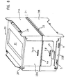
- a container for circular discs (e.g. record carrier plates) is shown, which consists of two base parts 1 and 2 and two cover parts 3 and 4. When assembled, these four parts form a completely closed container.
- Parts 1 and 3 can be regarded as a base body or box which can be closed by the "cover” consisting of parts 2 and 4.
- Cover consisting of parts 2 and 4.
- Box and “lid” can, however, be redefined as they are identical here.
- Base body or support part 1 and cover or closure part 3 can be connected to one another, for example, by locking devices designed as plug-in or spring elements 5 and 6, projections on the support part 1 projecting into recesses in the closure part 3 here.
- support part 2 and closure part 4 can be connected to one another be.
- Closure part 4 and support part 1 can be connected to one another by resiliently latching elements 7. Either elements 5 and 6 or element 7 can also be resilient.
- FIGS. 1 to 7 there is a projection 8 ′ attached to the support part 1, which protrudes into a recess 19 in the closure part 4.
- the closure parts 3 and 4 have an approximately L-shaped cross section (Fig. 4).
- closure parts 3 and 4 are expediently made of elastically deformable, in particular thermoplastic, plastic, so that the arm of the L-shape or the wall 9 or 9 'can be bent as a whole until it protrudes beyond the projection 8 or B'. Due to the resilience of the walls 9 and 9 'they snap over the projections 8 and 8' and the parts 1, 2 are locked together. When both closure parts 3 and 4 are in their locking position, the four individual parts 1 to 4 are locked together and the container is completely closed.
- the closure parts 3 and 4 can also consist of a tough elastic plastic, such as polypropylene, polyethylene or polyester.
- the wall 9 or 9 'easier to bend it can also be made narrower than the wall 10 or 10' of the closure parts 3 and 4, the latter serving as a storage space for the container in this example.
- the lid or closure parts 3 and 4 can also be produced from non-elastic or only partially elastic plastic. In principle, it is also possible to make the lid parts 3 and 4 more or less elastic in some areas, for example by providing film hinges etc. These measures must enable the container parts to be locked and closed in a functionally sufficient manner.
- the base body or support parts 1 and 2 can also consist of plastic, for example polyamide, but they can also be made of metal, metal alloys, e.g. Aluminum or magnesium or also consist of ceramic materials. Like the lid or closure parts, they should be used in series production processes such as Injection molding, PreB or sintering processes can be produced.
- the support parts 1 and 2 are substantially frame-shaped, with large openings 35, 36 on two opposite sides. This makes the support parts 1 and 2 particularly easy to clean.
- the disks 16 can easily be inserted into and removed from the disks, for example by hand on the outer edge of the disk 16 or mechanically on the inner edge of the opening 37 of the disk 16. This means that loading and unloading can also be done very easily and automatically.
- a large number of receiving grooves 11 are provided in the support parts 1 and 2.
- the grooves 11 do not have to be curved on their bottom surfaces, but they can run in a straight line there, so that the disks 16 do not abut the lines of the grooves 11 but in a point-like manner.
- the supporting part 2 has corresponding lugs 14 and 15. It is important that the grooves 11 are deep enough to hold the plates 16 shown in broken lines in FIG. 3 so that they cannot deflect in the transverse direction.
- the grooves can expediently have an approximately trapezoidal cross section, cf. e.g. Fig. 9.
- the disks 16 are thus fixed in their position in the container by the grooves 11 and, if the grooves 11 are not made too narrow, the disks 16 are not damaged either. Such damage to the coating of the disks 16 can be avoided if a relatively loose uptake into the grooves 11 can take place.
- the stability of the disks in the lateral direction is a question of the height or depth of the grooves 11, which can in any case be chosen so that sufficient stability can be achieved without additional holding means for the individual disk or the majority of the disks.
- the latter applies in particular to panes that are no longer or cannot be damaged at the moment of being placed in the container, e.g. Substrate plates for magnetic recording media, optical plates, circuit boards, wafers, records, etc.
- indentations or projections 17 and 18 can be provided on the closure parts 3 and 4, which protrude into the container in the closed position and can come into contact with the upper edge of the disk periphery. These indentations 17 and 18 serve as holding devices for the disks 16 on both sides. Each indentation 17, 18 can also be resilient, as a result of which it presses against the peripheral edge of the disks 16. The disks 16 are then clamped between the two indentations 17 and 18 and they are pressed against the bottom of the grooves 11.
- each closure part 3 or 4 there can be at least one such indentation 17 or 18, which is expediently arranged approximately in the middle.
- the indentations can also be attached off-center. However, you should always, diametrically opposed to the discs 16 overlap. Two or more indentations or protrusions can also be attached to each closure part.
- the projections can also be realized as material thickenings. But they can be rigid, e.g. if only a small elasticity is applied by the wall 10 itself.
- Each indentation 17 or 18 can be continuous and can be adapted in cross section to the peripheral contour of the disks 16. As is clear in FIG. 2, it is also possible and advantageous to form the indentations 17, 18 from a multiplicity of transverse ribs 32, the spacing and shape of which can be adapted to those of the grooves 11.
- the disks 16 are pressed against the bottom surface of the grooves 16 via each of the indentations 17 or 18, so that the disks 16 are also fixed in time.
- the security against lateral deflection of the plates 16 is greater with two mutually opposite projections 17 and 18.
- closure parts 3 and 4 with the same shape but from different materials, which means e.g. only one of the indentations could be resilient.
- the transverse ribs 32 are designed as bulges of the walls 10 and 10 '. They have an approximately V-shaped cross section. When firmly resting on the peripheral surface of the disks 16, the transverse ribs 32 can be pressed in elastically, so that their cross-sectional shape changes. The wall thickness of the ribs 32 can be reduced compared to the other wall thickness of the closure parts 3 and 4.
- this container is the formation of the possibly elastic indentations, which e.g. are formed as a continuous bulge of a wall of the closure parts. These indentations or projections are therefore part of the wall of the closure parts, so that they are relatively insensitive and can hardly be damaged. Any elastic deformability that may be required can also be obtained through their shape. They can be pressed against the panes when the container is closed and filled. As a result, the disks can be constantly pressed into the grooves and thus held securely and immovably in their position.
- FIGS. 8 to 14 show a further embodiment of the invention, a container 20 with basic body parts 21 A and B, hereinafter referred to as "support point”, and cover parts 22 A and B, hereinafter referred to as "closure parts".
- the supporting parts 21 A and B are of identical design, which, as is also true for the container of FIGS. 1 to 7, means that both parts are to be able to be produced from the same molds.
- the support parts 21 A and B are each in one position (in same direction next to each other with the same training in the vertical direction) identical or even identical in the borderline case.
- the support parts 21 A and B or the base body 21 are assigned to the closure parts 22 A and B, each of which, if necessary, could also be formed in two parts, but which can also be formed in one piece, for example a first common wall for closing both openings 35 and 36 and only one-sided connecting wall.
- the design of the closure parts 22 A and B corresponds essentially to that of parts 3 and 4 from FIGS. 1 to 7, with the difference of a trapezoidal cross-sectional shape instead of the triangular shape of the ribs 32 in FIG. 2. Substantially identical parts will also be the same in the following designated.
- parting line 33 which is formed by a nested spatial interlocking of the e.g. circumferential sealing webs 23 a and b and sealing grooves 24a and b is formed.
- the sealing webs and grooves 23 and 24 are part of the stacking devices of this container, and they are provided on the edge 25 of each support member 21 A and B.
- the edge 34 is the peripheral edge of each part 21 A or 21 B and delimits the respective part-specific opening 37. In the case of support parts 21 A and 21 B joined together with the sealing webs and grooves 23 and 24, the openings 37 thus come to lie on one another.
- the sealing webs and grooves 23 and 24 are arranged on each supporting part in such a way that, in relation to the vertical transverse axis 3B and the part-opening 37 located above, the sealing webs 23 on one side, in FIG. left, and the sealing grooves 24 are arranged to the right of it.
- the supporting part 21 A must first be rotated in the horizontal plane (perpendicular to the plane of the drawing) and then in a vertical plane (in the plane of the drawing) so that an arrangement for joining the supporting parts 21 A and B is achieved.
- the support part 21 B has on its underside the opening 36 which is surrounded by the outer edge 26.
- the outer edge or opening edge 26 is also formed with stacking devices, which consist of contour webs 27 and corresponding cutouts 28.
- Support part 21 A corresponds contour webs 27 and cutouts 28 on its upper side, in particular on the outer opening edge 26.
- the member 21 B is placed after rotation through 180 0 in a Horinzontalebene on the support part 21A.
- the base body unit 21 consisting of the assembled supporting parts 21 A and 21 B can be stacked vertically in a plurality.
- an inner edge 31 is provided in cross section, which borders the openings 35 and 36 directly.
- the cover part 22 A or 22 B is put over this inner edge 31, a secure closure being achieved when.
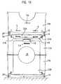
- the height of the cover part 22 A and 22 B in the closed position is lower than the height of the contour web 27 and possibly other support elements, so each support part 21 A or 21 B provided with a cover part 22 A or B is individually stackable as well as the whole Basic body unit complete with two lids, see Figure 15.
- the cover wall serving to lock the cover part 22 can be made narrower than the distance a between the long sides of the outer opening edge 26 of each support part 21 A or 21 B. It is important that the stacked by two Support parts 21 A and 21 B formed axial circular opening 39 is closed in the closed position of the cover part.
- support elements which are provided, for example, at a distance from the wall thickness, in each case in the region of the cutouts 28 and which protrude in height above the cutout contour 28.
- Such support elements are the ribs 29, 30, which are arranged perpendicular to the wall with the edge 26.
- the ribs 29 and 30 of the supporting parts 21 B and 21 A have a height which corresponds to approximately half the height of the end parts of the cutout contour 28.
- each groove 11 advantageously having a trapezoidal cross section.
- Any grooves 40 can advantageously also be formed with a trapezoidal cross section.
- the bottoms of the grooves 11 can have a circular shape but also a straight shape, for example as circular tangents 41 A, 41 B in FIG. 10 exhibit. In this illustration, the bottom of each groove 11 is designed as a flat surface or as spaced-apart surface pieces.
- peripheral edge 42 of the cover parts 22 A and B is formed for better sealing as a double edge, which receives the edge of the inner wall between them and closes off on one side.
- the locking of each cover part with one or two support parts 21 A or 21 B takes place via recesses or projections (5, 6, 7. 8, 8 ', 19), which are located both on the end parts of the cover parts 22 and on the end faces the support parts 21 A and B can be.
- a further recess / projection combination 7a can also be made on the same supporting part 21 A or 21 B, e.g. be provided in the vicinity of the partial opening 39, which further favors a supporting part / cover part unit, cf. Fig. 8.
- a grip tab 43 facilitates both locking and unlocking the locking elements.
- Fig. 9 A detailed representation of the container.
- the edges 34 of the two supporting parts are provided opposite one another with webs (23) and grooves (24), which ensure an accurate and non-displaceable position of the upper and lower part relative to one another.
- Fig. 10 it can be seen that the supporting parts are double-walled on the long sides.
- the two outer edges serve as supports when used as a lower part, as an upper part for receiving a further container placed on.
- Fig. 11 In the exploded individual part representation of a front view, the openings required for a mechanical pane removal can be clearly seen on the front and top and bottom.
- the lids fit into the peripheral edge of the rectangular openings, the sides of which are formed by the end walls and the vertical inner walls.
- the panes that protrude half in the lower part can be easily removed by hand by gripping the outer edge.
- the lower cover only needs to be removed when the machine is removed.
- Fig. 12 shows a plan view of a lower container part (lower support part) with a lid.
- the cover is shown in two embodiments (separated by the central length axis). It can be smooth (right) or with additional grooves (left). In the first example, additional edge contact elements on the circumference of the panes may then be necessary.
- Fig. 13 shows the front view of a complete container with lids, on which a supporting part (lower part) of another container (without a lid) is placed.
- the stacking of container parts is possible with and without lid parts.
- the support and position lock is only on the outer side walls.
- the lids are spaced inwards from the side walls.
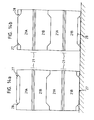
- 14a and b show a plurality of containers placed one on top of the other in both side views (right and left, respectively, based on the view in FIG. 13).
- each support part forms a half-shell, circular, predominantly or, as shown, polygon-like, which is designed in accordance with the outline (in the example: diameter) of the disks and is interrupted at the top or bottom.
- comb-like elevations 47 serve to keep the disks at a distance.
- Both supporting parts together enclose the panes on both sides in a large angular range, and the latter are thus secured in all positions without play.
- pins and bores can also be provided for the positionally accurate connection between the upper and lower part of a container.
- clip or snap connections or bolts and bores can be attached.
Abstract
Description
Die Erfindung betrifft einen Behälter für eine Mehrzahl von scheibenförmigen Gegenständen, insbesondere Aufzeichnungsträgern, bestehend aus einem an wenigstens zwei Seiten offenen Grundkörper mit einer Mehrzahl von Aufnahmerillen für die Gegenstände und aus wenigstens einem Deckelteil sowie aus zwischen Grundkörper und Deckelteil(en) vorgesehenen lösbaren Verriegelungeinrichtungen, und einen Behälterteil davon.The invention relates to a container for a plurality of disk-shaped objects, in particular record carriers, consisting of a base body open on at least two sides with a plurality of receiving grooves for the objects and at least one cover part and releasable locking devices provided between the base body and cover part (s), and a container part thereof.
Es ist ein derartiger Behälter für Speicherscheiben bekannt, der aus einem mittels eines Deckels verschließbaren Kasten besteht, in dem eine Vielzahl von parallel zueinander liegenden Rillen angebracht ist, deren lichte Weite der Breite einer Datenträgerplatte entspricht und die entsprechend den Abmessungen der Datenträgerplatten verlaufen, und der mindestens zwei dünne voneinander getrennte, in das Innere des Behälters ragende elastisch verformbare Vorsprünge aufweist, die sich quer zur Richtung der Rillen über den gesamten Bereich erstrecken, in dem Rillen vorhanden sind, und die bei in den Behälter eingesetzten Datenträgerplatten an mindestens zwei in Umfangsrichtung gegeneinander vesetzten Stellen an denselben satt anliegen (DE-OS 34 29 244).Such a container for storage disks is known, which consists of a closable by means of a lid box, in which a plurality of mutually parallel grooves are mounted, the inside width corresponds to the width of a disk and which run according to the dimensions of the disk, and has at least two thin, elastically deformable projections which are separate from one another and project into the interior of the container and extend transversely to the direction of the grooves over the entire area in which grooves are present, and which in the case of data carrier disks inserted into the container on at least two in the circumferential direction against one another cross-stitched areas at the same fit (DE-OS 34 29 244).
In diesem bekannten Behälter können die Platten gegen Verschmutzung und mechanische Beschädigung geschützt untergebracht werden. Die in diesem Behälter angebrachten Rillen halten die Platten auf Abstand, so daß sie sich beim Transport des Behälters nicht berühren können. Durch die elastisch verformbaren Vorsprünge werden die Platten in die Rillen gedrückt und so in ihrer Position fixiert. Die Vorsprünge sind bei dem bekannten Behälter als relativ materialarme Lamellen ausgebildet, deren Elastizität schnell nachläßt. Außerdem können die dünnen Lamellen leicht abbrechen, so daß die Platten dann nicht mehr ausreichend geschützt sind. Der Kasten dieses Behälters ist insgesamt so hoch wie die mit ihm zu transportierenden Platten. Daraus ergibt sich der Nachteil, daß die Platten nur mit Schwierigkeiten in den Kasten einsetzbar sind. Außerdem ist der Kasten dadurch schlecht zu reinigen. Um die unbedingt erforderliche Reinigung zu erleichtern, hat der bekannte Behälter einen abnehmbaren Boden. Dadurch wird der Behälter insgesamt aufwendig, da mit Kasten, Deckel und Boden drei unterschiedlich aufgebaute und getrennt herzustellende Teile benötigt werden.In this known container, the plates can be protected against contamination and mechanical damage. The grooves in this container keep the plates at a distance so that they cannot touch during transport of the container. Due to the elastically deformable projections, the plates are pressed into the grooves and thus fixed in their position. The projections are formed in the known container as relatively low-material slats, the elasticity of which quickly subsides. In addition, the thin slats can easily break off, so that the plates are no longer adequately protected. The box of this container is overall as high as the plates to be transported with it. This results in the disadvantage that the plates can only be inserted into the box with difficulty. It also makes the box difficult to clean. In order to facilitate the absolutely necessary cleaning, the known container has a removable bottom. This makes the container complex as a whole, since three differently constructed and separately manufactured parts are required with the box, lid and base.
Mit der PCT-OS WO 86100746 ist ein Behälter für dünne Gegenstände, insbesondere FlexyDisks® (0 eingetragenes Warenzeichen der BASF Aktiengesellschaft) bekannt, wobei zwei äußerlich identische Behälterhälften einen allseitig geschlossenen, mit Aufnahmeelementen für die FlexyDisks versehenen Behälter bilden. Die Aufnahmeelemente sind durch im Querschnitt L-förmige Elemente mit Nuten für die Kanten einer FlexyDisk gebildet, wobei die Elemente in jeder Behälterhälfte angeordnet sind. Dadurch ist der Abstand zwischen den einzelnen FlexyDisks in jeder Hälfte größer, als wenn jede der Hälften einen Einzelbehälter bildete. Die Hälften sind gelenkig miteinander verbindbar. Dieser Behälter ist ein reiner Archivbehälter und aufgrund seiner vielen Einzelteile ebenfalls nur aufwendig herstellbar.PCT-OS WO 86100746 is a container for thin objects, in particular FlexyDisks® (0 registered trademark of BASF Aktiengesellschaft shaft) is known, two externally identical container halves forming a container which is closed on all sides and provided with receiving elements for the FlexyDisks. The receiving elements are formed by L-shaped elements with grooves for the edges of a FlexyDisk, the elements being arranged in each half of the container. This means that the distance between the individual FlexyDisks is larger in each half than if each of the halves formed a single container. The halves are articulated together. This container is a purely archive container and, due to its many individual parts, is also difficult to manufacture.
Scheibenförmige Gegenstände im Rahmen der vorliegenden Erfindung können beliebige Scheibenkörper wie, z.B. gedruckte Schaltungen, Wafers für integrierte Schaltungen usw. oder auch jede Art von scheiben- oder plattenförmigen Aufzeichnungsträgern sein wie Magnetplatten, optische, magnetooptische, oder elektrische Speicherplatten für Speicherzwecke beliebiger Informationen, in analoger, digitaler oder bildlicher Form. Anhand von Datenträgerplatten wird im folgenden der Zweck eines Behälters nach der Gattung vorliegender Erfindung erläutert.Disk-shaped objects within the scope of the present invention can be any disk body such as, e.g. Printed circuits, wafers for integrated circuits, etc., or any type of disk or plate-shaped recording medium, such as magnetic disks, optical, magneto-optical, or electrical storage disks for storing any information, in analog, digital or pictorial form. The purpose of a container according to the genus of the present invention is explained below using data carrier disks.
7 "Datenträgerplatten" - im folgenden kurz als "Platten" bezeichnet - können beispielsweise Magnetspeicherplatten für EDV-Anlagen sein, die einen beschichteten Metallkörper aufweisen. Bei den Platten kann es sich aber auch um andere, einen beschichteten, steifen Grundkörper aufweisende Datenträger handeln, wie beispielsweise sogenannte Digitalmagnetplatten. Die für die Speicherung von Daten vorhandene Schicht ist sehr empfindlich. Die Platten müssen daher schom im Herstellerwerk, bei der Herstellung, beim Transport vom Herstellerwerk zum Verbraucher, aber auch später sehr sorgfältig behandelt werden. Dabei ist insbesondere darauf zu achten, daß die empfindliche Beschichtung nicht beschädigt wird.7 "data carrier disks" - hereinafter referred to briefly as "disks" - can be, for example, magnetic storage disks for EDP systems which have a coated metal body. However, the disks can also be other data carriers having a coated, rigid base body, such as so-called digital magnetic disks. The layer available for the storage of data is very sensitive. The plates must therefore be handled very carefully in the manufacturing plant, during manufacture, during transport from the manufacturing plant to the consumer, but also later. It is particularly important to ensure that the sensitive coating is not damaged.
Der Erfindung liegt die Aufgabe zugrunde, einen Behälter bereitzustellen, der die zu umfassenden oder zu umschließenden Scheiben wirksam schützt, bei besserer Zugänglichkeit, und der vielseitig verwendbar ist.It is the object of the invention to provide a container which effectively protects the panes to be encompassed or enclosed, with better accessibility, and which is versatile.
Die Aufgabe wird mit einem Behälter der eingangs definierten Art gelöst, wenn der Grundkörper aus zwei zusammensetzbaren, jeweils im wesentlichen gleichen Teilen besteht und zwei weitere, jeweils im wesentlichen gleiche Deckelteile vorgesehen sind, wobei jeder Deckelteil mindestens eine der Öffnungen des Grundkörpers mindestens teilweise abdeckt und die Verriegelungseinrichtungen zumindest an einem Deckelteil vorgesehen sind, mittels der die beiden Teile des Grundkörpers lösbar miteinander verriegelbar sind.The object is achieved with a container of the type defined in the introduction if the base body consists of two composable, essentially identical parts and two further, essentially identical cover parts are provided, each cover part at least partially covering at least one of the openings of the base body and the locking devices are provided at least on a cover part, by means of which the two parts of the base body can be releasably locked together.
Damit wird ein Mehrzweckbehälter geschaffen, der für Transport, Lagerung, Zwischenablage und Entnahme von hochempfindlichen Scheiben per Hand und maschinell gleichermaßen geeignet ist und für Hersteller und Anwender der Scheiben unentbehrlich ist.This creates a multi-purpose container that is equally suitable for transport, storage, intermediate storage and removal of highly sensitive panes by hand and by machine and is indispensable for manufacturers and users of the panes.
Es wird vorteilhaft die Entnehmbarkeit mehrerer oder einzelner Scheiben dadurch ermöglicht, daß z.B. Kreisscheiben an ihren Außendurchmessern klemmend und ergreifbar und schnell und ohne Gefahr einer Beschädigung oder Verschmutzung heraushebbar werden.The removability of several or individual panes is advantageously made possible by the fact that e.g. Circular disks can be gripped and gripped by their outer diameters and can be lifted out quickly and without risk of damage or contamination.
Durch die günstige konstruktive Gestaltung des Behälters, wie auch aus dem folgenden hervorgeht, können die Herstellkosten solcher Behälter erheblich gesenkt werden.Due to the favorable structural design of the container, as can also be seen from the following, the manufacturing costs of such containers can be reduced considerably.
Der erfindungsgemäße Behälter besteht zwar insgesamt aus vier Teilen. Da dieselben jedoch paarweise im wesentlichen gleich oder sogar identisch sind, brauchen nur zwei unterschiedlich gestaltete Teile hergestellt zu werden. Der Fertigungsaufwand ist also gering, und es brauchen nur zwei unterschiedliche Teile bevorratet zu werden. Der Behälter läßt sich einfach reinigen, wenn die Grundkörperteile nur etwa die halbe Höhe des Behälters einnehmen und daher innen leicht zugänglich sind. Die Deckelteile sind für eine Reinigung unproblematisch, da sie von allen Seiten zugänglich ausbildbar sind.The container according to the invention consists of a total of four parts. However, since they are essentially identical or even identical in pairs, only two differently designed parts need to be produced. The manufacturing effort is therefore low, and only two different parts need to be stored. The container can be easily cleaned if the body parts only occupy about half the height of the container and are therefore easily accessible from the inside. The cover parts are unproblematic for cleaning, since they can be made accessible from all sides.
Ein weiterer Vorteil dieses Behälters besteht darin, daß im Falle der Beschädigung eines Teils dasselbe wegen der im wesentlichen paarweisen Identität leicht austauschbar ist.Another advantage of this container is that in the event of a part being damaged, it is easily interchangeable due to the essentially paired identity.
In praktischer Ausgestaltung weisen die Deckelteile im Seitenriß L-Form auf, und jeder Arm der L-Form umfaßt eine Seite des Grundkörpers im Seitenriß.In a practical embodiment, the cover parts have an L-shape in the side elevation, and each arm of the L-shape comprises one side of the base body in the side elevation.
Dadurch sind die Deckeleile einfach und wirtschaftlich herstellbar und leicht zu reinigen.This makes the cover parts simple and economical to manufacture and easy to clean.
Im weiteren kann jeder Arm der L-Form mit Verriegelungselementen, insbesondere Aussparungen ausgebildet sein, während die umgriffenen Seitenflächen der Grundkörperteile mit entsprechenden Verriegelungselementen, insbesondere mit Vorsprüngen, ausgebildet sein können.Furthermore, each arm of the L-shape can be designed with locking elements, in particular recesses, while the encompassed side surfaces of the base body parts can be designed with corresponding locking elements, in particular with projections.
Damit wird bereits durch ein Deckelteil eine Verbindung der beiden Grundkörperteile herstellbar.A connection of the two base body parts can thus already be established by a cover part.
In weiterer Ausbildung kann jeweils der die eine der zwei Öffnungen des Grundkörpers verschließende Arm der L-Form-Deckelteile mit den Aufnahmerillen des Grundkörpers zugeordneten Halteeinrichtungen ausgebildet sein.In a further embodiment, the arm of the L-shaped cover parts that closes one of the two openings of the base body can be designed with holding devices assigned to the receiving grooves of the base body.
Dadurch wird eine rüttelsichere Lage der Scheiben bei geschlossenem Behälter erreicht. Praktisch können die Halteeinrichtungen als Einbuchtungen oder Ausbuchtungen am Arm des Deckelteils gestaltet sein.This ensures a vibration-proof position of the panes when the container is closed. In practice, the holding devices can be designed as indentations or bulges on the arm of the cover part.
Praktisch können die Halteeinrichtungen als mindestens ein federelastisches Element, insbesondere als Einbuchtung des Deckelteils mit U- oder Wannenquerschnittsform.In practice, the holding devices can be used as at least one spring-elastic element, in particular as an indentation of the cover part with a U or trough cross-sectional shape.
Zweckmäßig können die Aufnahmerillen der Grundkörperteile und/oder die Gegenstücke der Halteeinrichtung etwa trapezförmigen Querschnitt aufweisen, wodurch die Scheiben schonend einsetzbar und eng tolerierbar aufzubewahren sind. Günstig ist eine Ausführung, in der der Boden der Aufnahmerillen an den Grundkörperteilen annähernd eine Kreisbogen-Fläche und insbesondere eine unterbrochene Kreisbogen-Fläche aufweist.The receiving grooves of the base body parts and / or the counterparts of the holding device can expediently have an approximately trapezoidal cross section, as a result of which the disks can be used in a gentle manner and stored in a closely tolerable manner. A favorable embodiment is one in which the base of the receiving grooves on the base body parts has approximately a circular arc area and in particular an interrupted circular arc area.
In weiterer herstellungsmäBig und als Lagerung für Kreisscheiben günstigen Ausbildung kann der Boden der Aufnahmerillen als ebene Fläche, insbesondere als mehrere, voneinander beabstandete Flächenstücke ausgebildet sein.In a further construction which is favorable in terms of manufacture and as a bearing for circular disks, the bottom of the receiving grooves can be designed as a flat surface, in particular as a plurality of surface pieces spaced apart from one another.
Wegen seiner besseren und raumsparenden Handhabung, Archivierung und Transportierung können die Teile des Grundkörpers zumindest in der Nähe der wenigstens zwei Öffnungen des Grundkörpers mit Stapeleinrichtungen ausgebildet sein.Because of its better and space-saving handling, archiving and transportation, the parts of the base body can be formed with stacking devices at least in the vicinity of the at least two openings of the base body.
Konstruktiv können die Stapeleinrichtungen miteinander flächig und/oder räumlich verschachtelbare Wandteile der Grundkörperteile sein.In terms of construction, the stacking devices can be flat and / or spatially nestable wall parts of the base body parts.
Praktisch können die Stapeleinrichtungen an den Grundkörperteilen derartig angeordnet sein, daß eine Symmetrie zur vertikalen Mittelachse des Seitenrisses zweier aufeinander gestapelter Grundkörperteile besteht.In practice, the stacking devices can be arranged on the base body parts in such a way that there is symmetry with the vertical central axis of the side tear of two base body parts stacked one on top of the other.
Vorteilhaft können die Stapeleinrichtungen deckungsgleich angeordnete Vorsprünge und Vertiefungen sein, die derartig angeordnet sind, daß einer von beiden Grundkörperteilen um 1800 in der Horizontale gegenüber dem anderen Grundkörperteil gedreht und nach weiterer 180° Drehung in der Vertikalebene auf den anderen Grundkörperteil aufgesetzt ein Ineingriffkommen der einzelnen Stapelelemente bewirkt.Advantageously, the stacking means congruently arranged projections and recesses may be arranged such that a rotating of the two main body parts 180 0 in the horizontal relative to the other body part and, after further 180 ° rotation in the vertical plane on the other body part placed an engagement of the individual Stack elements causes.
Damit ergibt sich eine gute Stapelbarkeit bei Herstellung gleicher Grundkörperteile.This results in good stackability when producing the same basic body parts.
In praktischer Ausführung können die Stapeleinrichtungen wenigstens teilweise aus Dichtstegen und -nuten bestehen, die an zumindest einem Öffnungsrand eines Grundkörperteils und parallel zum Rand vorgesehen sein, so daß sich eine gute Dichtung der Teilungsfuge ergibt, die eine nahezu vollständige Abschirmung dadurch gewährleistet, daß an nahezu keiner Stelle ein direkter Wanddurchgang von innen nach außen oder umgekehrt existiert.In a practical embodiment, the stacking devices can at least partially consist of sealing webs and grooves, which are provided on at least one opening edge of a base body part and parallel to the edge, so that there is a good seal of the dividing joint, which ensures an almost complete shielding in that almost nowhere does a direct wall passage from inside to outside or vice versa exist.
In weiterer praktischer Ausgestaltung können die Stapeleinrichtungen wenigstens teilweise aus am Öffnungsrand vorgesehenen Konturstegen und entsprechenden Ausschnitten bestehen, so daß es möglich ist, die einzelnen Grundkörperteile auch zusammen mit aufgesetztem Deckelteil zu stapeln.In a further practical embodiment, the stacking devices can at least partially consist of contour webs and corresponding cutouts provided at the opening edge, so that it is possible to stack the individual base body parts together with the cover part attached.
Wenn sowohl die Dichtstege und -nuten als auch die Konturstege und Ausschnitte am selben Grundkörperteil verwendet werden, ergibt sich mit gleichen Teilen eine zweifache Stapelmöglichkeit mit unterschiedlichen Stapelelementen nach oben und unten. Zur besseren seitlichen Abstützung übereinandergestapelter Grundkörperteile können im Wanddickenabstand angeordnete Stützelemente jeweils im Bereich der Ausschnitte vorgesehen sein und in der Höhe über die Ausschnittkontur hervorragen.If both the sealing webs and grooves as well as the contour webs and cutouts are used on the same base body part, the same parts result in a double stacking option with different stacking elements up and down. For better lateral support of stacked base body parts, support elements arranged at a distance from the wall thickness can each be provided in the area of the cutouts and protrude in height above the cutout contour.
Zweckmäßig kann parallel zum äußeren Öffnungsrand ein innerer Öffnungsrand vorgesehen sein, der vom Deckelteil, insbesondere haubenartig, verschließbar ist, wodurch ein Verschluß der Öffnungten) ohne Verlust der Stapelbarkeit möglich wird.An inner opening edge can expediently be provided parallel to the outer opening edge, which can be closed by the cover part, in particular in a hood-like manner, as a result of which the openings can be closed without losing stackability.
Zweckmäßig kann die Höhe des Deckelteils (L-Arm) in Verschlußposition niedriger gewählt sein als die Höhe des Kontursteges bzw. der Stützelemente. Dadurch wird erreicht, daß die Grundkörperteile auch, wenn sie einseitig vom Deckelteil verschlossen sind. stapelbar sind, auch mit dazwischenliegendem Deckelteil. Dadurch wird die Handhabung verbessert und das volumenmäßige Lager- oder Archivierungsproblem ausgezeichnet gelöst.The height of the cover part (L-arm) in the closed position can expediently be chosen to be lower than the height of the contour web or of the support elements. This ensures that the base body parts even when they are closed on one side by the cover part. are stackable, even with the cover part in between. This improves handling and solves the volume-related storage or archiving problem excellently.
Zweckmäßig sind die Deckelteile zumindest im Bereich der die Öffnung des Grundkörperteils abdeckenden Wand schmaler als der Abstand der langen Seiten des äußeren Öffnungsrandes voneinander.The cover parts are expediently narrower than the distance between the long sides of the outer opening edge, at least in the region of the wall covering the opening of the base part.
Die Erfindung bezieht sich auch auf die zweckmäßige Ausgestaltung eines der Behälter- oder Tragteile, wenn dieses gekennzeichnet ist durch einen etwa rechteckigen, aus Wänden bestehenden Rahmen, durch Aufnahmerillen für die scheibenförmigen Gegenstände an den Innenseiten zweier, einander gegenüberliegender Wände und durch Stapeleinrichtungen an wenigstens einem Stirnrand der beiden einander gegenüberliegenden Wände zum Übereinanderstapeln mehrerer Behälterteile.The invention also relates to the practical design of one of the container or support parts, if this is characterized by an approximately rectangular frame consisting of walls, by receiving grooves for the disk-shaped objects on the inside of two opposing walls and by stacking devices on at least an end edge of the two opposite walls for stacking several container parts.
Die Erfindung wird nachfolgend anhand von in der Zeichnung dargestellten Ausführungsbeispielen beschrieben.The invention is described below with reference to exemplary embodiments shown in the drawing.
Es zeigen:
- Fig. 1 eine Frontansicht eines verschlossenen Behälters nach der Erfindung
- Fig. 2 eine Seitenansicht des Behälters, teilweise geschnitten
- Fig. 3 einen Schnitt durch den Behälter nach Fig. 2 längs der Linie III - III
- Fig. 4 und 5 den Verschlußteil, wobei Fig. 5 eine Ansicht von Fig. 4 in Richtung des Pfeiles A ist
- Fig. 6 und 7 den Tragteil, wobei Fig. 7 ein Schnitt durch Fig. 6 längs der Linie VII - VII ist
- Fig. 8 eine Variante eines Behälters nach der Erfindung
- Fig. 9 der Behälter aus Fig. 8 in Einzelteildarstellung in Seitenan-' sicht
- Fig. 10 ein Querschnitt des Behälters aus Figur 8 gemäß Schnittlinie X - X
- Fig. 11 der Behälter gemäß Fig. 8 in Einzelteildarstellung in Vorderansicht
- Fig. 12 eine Draufsicht auf einen Grundkörperteil mit unten angeordnetem Deckelteil
- Fig. 13 eine Vorderansicht eines kompletten Behälters einschließlich der Deckelteile und einem aufgesetzten, weiteren Grundkörperteil
- Fig. 14 a und b schematische Seitenansichten (in verkleinertem Maßstab) von je zwei gestapelten Behältern.
- Fig. 1 is a front view of a closed container according to the invention
- Fig. 2 is a side view of the container, partially sectioned
- Fig. 3 shows a section through the container of FIG. 2 along the line III - III
- 4 and 5 the closure part, wherein Fig. 5 is a view of Fig. 4 in the direction of arrow A.
- 6 and 7 the supporting part, wherein Fig. 7 is a section through Fig. 6 along the line VII - VII
- Fig. 8 shows a variant of a container according to the invention
- Fig. 9 of the container of Fig. 8 in partial view in side view
- 10 shows a cross section of the container from FIG. 8 along the section line X - X
- Fig. 11 of the container of FIG. 8 in partial view in front view
- Fig. 12 is a plan view of a base part with the cover part arranged below
- Fig. 13 is a front view of a complete container including the lid parts and an attached, further base body part
- 14 a and b are schematic side views (on a reduced scale) of two stacked containers.
In Fig. 1 ist ein Behälter für kreisrunde Scheiben (z.B. Aufzeichnungsträgerplatten) dargestellt, der aus zwei Grundkörperteilen 1 und 2 und zwei Deckelteilen 3 und 4 besteht. In zusammengebautem Zustand ergeben diese vier Teile einen rundum geschlossenen Behälter. Die Teile 1 und 3 können dabei als Grundkörper oder Kasten angesehen werden, der durch den aus den Teilen 2 und 4 bestehenden "Deckel" verschließbar ist. "Kasten" und "Deckel" sind jedoch beliebig neu festlegbar, da dieselben hier identisch sind.In Fig. 1, a container for circular discs (e.g. record carrier plates) is shown, which consists of two
Grundkörper- oder Tragteil 1 und Deckel- oder Verschlußteil 3 sind beispielsweise durch als Steck- oder Federelemente 5 und 6 ausgebildete Verriegelungseinrichtungen miteinander verbindbar, wobei hier Vorsprünge am Tragteil 1 in Aussparungen des Verschlußteils 3 hineinragen. In gleicher Weise können Tragteil 2 und Verschlußteil 4 miteinander verbunden sein. Verschlußteil 4 und Tragteil 1 können durch federnd einrastende Elemente 7 miteinander verbunden sein. Es können auch entweder Elemente 5 und 6 oder Element 7 federelastisch sein. Im Beispiel der Figuren 1 bis 7 handelt es sich um einen am Tragteil 1 angebrachten Vorsprung 8', der in eine Aussparung 19 des Verschlußteils 4 hineinragt. Die Verschlußteile 3 und 4 haben einen etwa L-förmigen Querschnitt (Fig. 4). Sie sind zweckmäßig aus elastisch verformbarem, insbesondere thermoplastischem, Kunststoff hergestellt, so daß der Arm der L-Form oder die Wand 9 bzw. 9' insgesamt so weit gebogen werden kann, bis sie über den Vorsprung 8 bzw. B' ragt. Infolge der Federelastizität der Wände 9 und 9' schnappen diese über die Vorsprünge 8 und 8' und die Teile 1, 2 sind miteinander verriegelt. Wenn beide Verschlußteile 3 und 4 in ihrer Verriegelungsposition sind, sind die vier Einzelteile 1 bis 4 miteinander verriegelt und der Behälter ist vollständig verschlossen. Die Verschlußteile 3 und 4 können auch aus einem zähelastischen Kunststoff, wie beispielsweise Polypropylen, Polyethylen oder Polyester bestehen. Zur leichteren Biegbarkeit der Wand 9 bzw. 9' kann diese auch schmaler ausgeführt sein als die Wand 10 bzw. 10' der Verschlußteile 3 und 4, wobei letztere in diesem Beispiel als Stellfläche für den Behälter dient. Die Deckel- oder Verschlußteile 3 und 4 sind auch aus nicht oder nur teilweise elastischem Kunststoff herstellbar. Es ist dabei grundsätzlich auch möglich, die Deckelteile 3 und 4 bereichsweise mehr oder weniger elastisch auszubilden z.B. durch Vorsehen von Filmscharnieren etc. Dabei müssen diese Maßnahmen ein funktionsmäßig ausreichend sicheres Verriegeln und Verschließen der Behälterteile ermöglichen.Base body or support
Die Grundkörper- oder Tragteile 1 und 2 können ebenfalls aus Kunststoff, beispielsweise aus Polyamid bestehen, sie können jedoch auch aus Metall, Metallegierungen, z.B. Aluminium- oder Magnesium oder auch aus keramischen Werkstoffen bestehen. Dabei sollten sie, ebenso wie die Deckel-oder Verschlußteile, in Serienproduktionsverfahren, wie z.B. Spritzguß-, PreB- oder Sinterverfahren, hergestellt werden.The base body or
Die Tragteile 1 und 2 haben entsprechend den Fig. 1 bis 3 etwa die halbe Höhe des Behälters, so daß zwei richtig zusammengefügte Tragteile 1 und 2 im wesentlichen die Höhe des Behälters bestimmen. Aus Fig. 7 ist zu erkennen, daß die Tragteile 1 und 2 im wesentlichen rahmenförmig ausgebildet sind, mit großen Öffnungen 35, 36 an zwei einander gegenüberliegenden Seiten. Dadurch sind die Tragteile 1 und 2 besonders einfach zu reinigen. Außerdem können die Scheiben 16, wenn die Höhe der Tragteile 1 und 2 etwa dem Scheibenradius r entspricht, leicht in dieselben eingesetzt und wieder aus denselben entnommen werden, z.B. per Hand am Außenrand der Scheibe 16 oder maschinell am Innenrand der Öffnung 37 der Scheibe 16. So kann die Bestückung und Entnahme auch sehr einfach automatisch erfolgen. In den Tragteilen 1 und 2 ist eine Vielzahl von Aufnahmerillen 11 (vgl. Fig. 2) angebracht. Die Rillen 11, die Kreisbogenform haben können, verlaufen hier nicht durchgehend, sondern für das Tragteil 1 nach Fig. 7 beispielsweise in zwei Ansätzen 12 und 13 des Tragteils. Die Rillen 11 müssen dabei an ihren Bodenflächen nicht gekrümmt sein, sondern sie können dort geradlinig eben verlaufen, so daß die Scheiben 16 nicht linienförmig, sondern punktförmig am Boden der Rillen 11 anliegen. Das Tragteil 2 hat entsprechende Ansätze 14 und 15. Wichtig ist, daß die Rillen 11 tief genug sind, um die in Fig. 3 strichpunktiert eingezeichneten Platten 16 so zu halten, daß sie nicht in Querrichtung ausweichen können. Zweckmäßig können die Rillen einen etwa trapezförmigen Querschnitt aufweisen, vgl. z.B. Fig. 9.1 to 3 have about half the height of the container, so that two correctly assembled
Die Scheiben 16 sind damit durch die Rillen 11 in ihrer Position im Behälter festgelegt und, wenn die Rillen 11 nicht zu eng ausgeführt sind, werden die Scheiben 16 auch nicht beschädigt. Eine solche Beschädigung der Beschichtung der Scheiben 16 ist vermeidbar, wenn eine relativ lose Aufnahme in die Rillen 11 stattfinden kann.The
Im übrigen ist die Standfestigkeit der Scheiben in seitlicher Richtung eine Frage der Höhe oder Tiefe der Rillen 11, die jedenfalls so gewählt werden kann, daß auch ohne weitere zusätzliche Haltemittel für die Einzelscheibe oder die Mehrzahl der Scheiben eine ausreichende Standfestigkeit erreichbar ist. Letzteres gilt besonders für Scheiben, die im Augenblick des Einbringens in den Behälter nicht mehr oder noch nicht beschädigbar sind, wie z.B. Substratplatten für Magnetaufzeichnungsträger, optische Platten, Schaltungsplatten, Wafers, Schallplatten usw.Moreover, the stability of the disks in the lateral direction is a question of the height or depth of the
Für Scheiben 11 mit empfindlicher Schicht ist es notwendig, diese in jeder Richtung festzulegen. Zu diesem Zweck können an den Verschlußteilen 3 und 4 Einbuchtungen oder Vorsprünge 17 bzw. 18 vorgesehen sein, die in Verschlußposition in den Behälter hineinragen und mit der Oberkante des Scheibenumfangs in Kontakt treten können. Diese Einbuchtungen 17 und 18 dienen als beiderseitige Halteeinrichtungen für die Scheiben 16. Jede Einbuchtung 17, 18 kann auch federelastisch sein, wodurch sie sich unter Druck an den Umfangsrand der Scheiben 16 anlegt. Die Scheiben 16 sind dann zwischen beiden Einbuchtungen 17 und 18 eingespannt und sie werden an den Boden der Rillen 11 gepreßt.For
In jedem Verschlußteil 3 oder 4 kann mindestens eine solche Einbuchtung 17 oder 18 vorhanden sein, die zweckmäßig etwa mittig angeordnet ist. Die Einbuchtungen können aber auch außermittig angebracht sein. Sie sollten sich aber immer, bezogen auf die Scheiben 16, diametral gegenüberliegen. Es können auch zwei oder mehr Einbuchtungen oder Vorsprünge an jedem Verschlußteil angebracht sein.In each
Die Vorsprünge sind auch als Materialverdickungen realisierbar. Sie können aber starr sein, z.B. wenn nur eine geringe Elastizität durch die Wand 10 selbst aufgebracht wird.The projections can also be realized as material thickenings. But they can be rigid, e.g. if only a small elasticity is applied by the
Jede Einbuchtung 17 oder 18 kann durchgehend ausgebildet sein und ist im Querschnitt an die Umfangskontur der Scheiben 16 anpaßbar. Es ist, wie in Fig. 2 deutlich, auch möglich und vorteilhaft, die Einbuchtungen 17, 18 aus einer Vielzahl von Querrippen 32 auszubilden, deren Abstand und Form denen der Rillen 11 angepaßt sein kann.Each
Prinzipiell werden die Scheiben 16 über jede der Einbuchtungen 17 oder 18 an die Bodenfläche der Rillen 16 gedrückt, so daß die Scheiben 16 auch zeitlich festgelegt sind. Für diese Funktion könnte es zwar prinzipiell ausreichen, wenn beispielsweise nur der Vorsprung 17 vorhanden wäre, während der Verschlußteil 3 keinen Vorsprung aufweist. Dann müßten aber pro Behälter zwei unterschiedlich geformte Verschlußteile hergestellt und eingesetzt werden, wodurch derselbe wieder aufwendiger würde. Außerdem ist die Sicherheit gegen seitliches Ausweichen der Platten 16 bei zwei einander gegenüberliegenden Vorsprüngen 17 und 18 größer.In principle, the
Es ist jedoch möglich, die Verschlußteile 3 und 4 formgleich, aber aus unterschiedlichen Werkstoffen herzustellen, wodurch z.B. nur eine der Einbuchtungen federelastisch sein könnte.However, it is possible to produce the
Die Querrippen 32 sind als Ausbauchungen der Wände 10 bzw. 10' ausgebildet. Sie haben einen etwa V-förmigen Querschnitt. Beim festen Anliegen an der Umfangsfläche der Scheiben 16 können die Querrippen 32 elastisch eingedrückt werden, so daß sich ihre Querschnittsform verändert. Die Wandstärke der Rippen 32 kann gegenüber der sonstigen Wandstärke der VerschluBteile 3 und 4 verringert sein.The
Der Zusammenbau des Behälters geschieht beispielsweise wie folgt:
- Es werden zunächst die
Tragteile 1 und 2 indie Verschlußteile 3 und 4 eingesetzt. Dabeigreifen die Verriegelungselemente 5 und 6 ineinander. Damit sind "Deckel" und "Kasten" fertiggestellt. Sie werden dadurch zum Behälter zusammengefügt, daß dieaus den Teilen 2 und 4 bestehende "obere Hälfte" um 1800 geschwenkt und auf den ausden Teilen 1 und 3 bestehenden "Kasten" aufgesetzt wird.Die Wände 9 und 9' werden dabei nach außen gebogen, so daß sie über dieVorsprünge 8 und 8' greifen können.Wenn die Tragteile 1 und 2 fest aufeinander liegen, werden dieWände 9 und 9' losgelassen, so daß dieVorsprünge 8 und 8' in deren Ausnehmungen 19 (Fig. 5) eingreifen oder einschnappen. Der Behälter ist damit verschlossen.Die Scheiben 16 werden gegebenenfalls vor dem Verschließen des Behälters z.B. inden Tragteil 1 eingesetzt.
- First, the
support parts closure parts locking elements parts parts walls 9 and 9 'are bent outwards so that they can grip over theprojections 8 and 8'. If the supportingparts walls 9 and 9 'get rid left so that theprojections 8 and 8 'engage or snap into their recesses 19 (Fig. 5). The container is now closed. Thedisks 16 are optionally used, for example, in the supportingpart 1 before the container is closed.
Das beschriebene Behälterbeispiel zeichnet sich durch folgende Merkmale dadurch aus
- - daß Kasten und Deckel als im wesentlichen identische, sich zu einem geschlossenen Behälter ergänzende Teile ausgebildet sind,
- - daß Kasten und Deckel jeweils aus einem inneren,
Rillen 11 aufweisenden Tragteil förmigen Verschlußteil - -
daß die Tragteile die Verschlußteile Stelle angebrachte Steckelemente - - daß die gegebenenfalls elastisch verformbaren Einbuchtungen 17, 18, insbesondere an
den beiden Verschlußteilen - - daß bei geschlossenem Behälter
die beiden Tragteile Deckels am Tragteil 1 des Kastens und umgekehrt durchVerriegelungselemente 8, 8' festlegbar ist. - - daß gegebenenfalls die
Einbuchtungen Nuten oder Rippen 32 aufweisen, deren Abstand voneinander dem Mittenabstand der Rillen 11 entspricht, und dieden Rillen 11 des Tragteils im wesentlichen gegenüberliegen.
- that the box and lid are designed as essentially identical parts which complement one another to form a closed container,
- that the box and the lid each consist of an inner, grooved 11 supporting
part closure part - that the supporting
parts closure parts plug elements - - That the optionally elastically
deformable indentations closure parts - - That when the container is closed, the two
support parts closure part 4 of the lid on thesupport part 1 of the box and vice versa can be fixed by lockingelements 8, 8 '. - - That the
indentations ribs 32, the spacing of which corresponds to the center distance of thegrooves 11, and which are essentially opposite thegrooves 11 of the supporting part.
Einer der Vorteile dieses Behälters liegt in der Ausbildung der gegebenenfalls elastischen Einbuchtungen, die z.B. als durchgehende Ausbauchung einer Wand der Verschlußteile ausgebildet sind. Diese Einbuchtungen oder Vorsprünge sind also Teil der Wand der Verschlußteile, so daß sie relativ unempfindlich und kaum zu beschädigen sind. Eine evtl. erforderliche elastische Verformbarkeit können sie auch durch ihre Gestalt erhalten. Sie können bei geschlossenem, gefülltem Behälter bei ihrer Anlage an die Scheiben angedrückt werden. Die Scheiben können dadurch ständig in die Rillen gedrückt und damit sicher und unverrückbar in ihrer Position gehalten werden.One of the advantages of this container is the formation of the possibly elastic indentations, which e.g. are formed as a continuous bulge of a wall of the closure parts. These indentations or projections are therefore part of the wall of the closure parts, so that they are relatively insensitive and can hardly be damaged. Any elastic deformability that may be required can also be obtained through their shape. They can be pressed against the panes when the container is closed and filled. As a result, the disks can be constantly pressed into the grooves and thus held securely and immovably in their position.
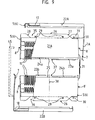
In den Figuren 8 bis 14 ist eine weitere Ausführung der Erfindung, ein Behälter 20 dargestellt mit Grundkörperteilen 21 A und B, im folgenden wieder als "Tragtelle" bezeichnet, und Deckelteilen 22 A und B, im folgenden wieder als "Verschlußteile" bezeichnet. Die Tragteile 21 A und B sind gleich ausgebildet, was, wie auch für den Behälter der Figuren 1 bis 7 gilt, soviel heiBt, daß beide Teile aus denselben Formen herstellbar sein sollen. Die Tragteile 21 A und B sind jeweils in einer Lage (in gleicher Richtung nebeneinander mit gleicher Ausbildung in Vertikalrichtung) gleich oder im Grenzfall sogar identisch ausgebildet. Aus beschriebener Lage ist beispielsweise Teile 21 A um 1800 drehbar gegenüber Teil 21 B und durch Drehung um weitere 180° in Vertikalebene auf den Teil 21 B aufsetzbar, wodurch sich der zweiteilige Grundkörper 21 ergibt, der oben und unten die Öffnungen 35 bzw. 36 aufweist (Fig. 9). Den Tragteilen 21 A und B bzw. dem Grundkörper 21 sind die Verschlußteile 22 A und B zugeordnet, die jeweils, wenn erforderlich auch zweiteilig ausgebildet sein könnten, die aber gemeinsam auch einteilig ausbildbar sind, etwa einer ersten gemeinsamen Wand zum Verschluß beider Öffnungen 35 und 36 und nur einer einseitigen Verbindungswandung. Die Ausbildung der Verschlußteile 22 A und B entspricht im wesentlichen der der Teile 3 und 4 aus Figur 1 bis 7. etwa mit dem Unterschied einer Trapez-Querschnittsform statt der Dreiecksform der Rippen 32 in Figur 2. Im wesentlichen gleiche Teile werden im folgenden auch gleich bezeichnet.FIGS. 8 to 14 show a further embodiment of the invention, a
Bei geschlossenem Behälter 20 ergibt sich eine im wesentlichen zumindest seitlich abgedeckte Trennfuge 33, die durch ein verschachtelt räumliches Ineinandergreifen der z.B. umlaufenden Dichtstege 23 a und b und Dichtnuten 24a und b gebildet wird. Die Dichtstege und -nuten 23 und 24 sind ein Teil der Stapeleinrichtungen dieses Behälters, und sie sind am Rand 25 jedes Tragteils 21 A und B vorgesehen. Der Rand 34 ist der Umfangsrand jedes Teils 21 A oder 21 B und begrenzt die jeweilige teileigene Öffnung 37. Bei mit den Dichtstegen und -nuten 23 bzw. 24 ineinander gefügten Tragteilen 21 A und 21 B kommen die Öffnungen 37 also aufeinander zu liegen.When the
Die Dichtstege und -nuten 23 und 24 sind an jedem Tragteil so angeordnet, daß, bezogen auf die vertikale Querachse 3B und oben liegender teileigenen Öffnung 37, die Dichtstege 23 an einer Seite, in Figur 9 beim Tragteil 21 B z.B. links, und die Dichtnuten 24 rechts davon angeordnet sind. Gegenüber dieser Lage des Tragteils 21 B ist also das Tragteil 21 A erstens in der Horizontalebene zu drehen (senkrecht zur Zeichenebene) und dann in einer Vertikalebene (in der Zeichenebene) damit eine Anordnung zum Zusammenfügen der Tragteile 21 A und B erreicht wird. Es ist jedoch ebenso möglich, rechts und links jeweils einen Steg 23 und einem Nut 24 parallel zueinander vorzusehen, so daß sich die Stege 23 und die Nuten 24 diagonal gegenüberliegen. Die Drehungen (jeweils um einen 180°-Drehwinkel) erfolgen dann ebenso wie vorstehend beschrieben.The sealing webs and
Der Tragteil 21 B hat an seiner Unterseite die Öffnung 36, die vom äußeren Rand 26 umschlossen ist. Der äußere Rand oder Öffnungsrand 26 ist ebenfalls mit Stapeleinrichtungen ausgebildet, die aus Konturstegen 27 und entsprechenden Ausschnitten 28 bestehen. Tragteil 21 A weist entsprechende Konturstege 27 und Ausschnitte 28 an seiner Oberseite, insbesondere am äußeren Öffnungsrand 26 auf. Der Teil 21 B ist nach Drehung um 1800 in einer Horinzontalebene auf den Tragteil 21 A aufsetzbar. Ebenfalls ist die aus den zusammgefügten Tragteilen 21 A und 21 B bestehende Grundkörpereinheit 21 in einer Mehrzahl in der Vertikalen stapelbar.The
In Figur 10 ist sichtbar, daß hier im Querschnitt ein Innenrand 31 vorgesehen ist, der die Öffnungen 35 bzw. 36 direkt umrandet. Über diesen Innenrand 31 wird der Deckelteil 22 A bzw. 22 B gestülpt, wobei ein sicherer Verschluß erreicht wird, wenn. wie dargestellt die Höhe des Deckelteils 22 A und 22 B in Verschlußposition niedriger ist als die Höhe des Kontursteges 27 und evtl. weiterer Stützelemente, so ist jeder mit einem Deckelteil 22 A und B versehener Tragteil 21 A oder 21 B einzeln ebenso stapelbar wie die gesamte Grundkörpereinheit komplett mit zwei Deckeln, s. Figur 15. Hier ist auch deutlich, daß die eine zur Verriegelung des Deckelteils 22 dienende Deckelwand schmaler ausbildbar ist als der Abstand a der langen Seiten des äußeren Öffnungsrands 26 jedes Tragteils 21 A oder 21 B. Es ist dabei wichtig, daß die durch zwei gestapelte Tragteile 21 A und 21 B gebildete Axial-Kreisöffnung 39 in Verschlußposition des Deckelteils geschlossen ist.It can be seen in FIG. 10 that an
Es ist zweckmäßig, insbesondere im Hinblick auf seitliche Relativbewegungen gestapelter Trag- oder Behälterteile, Stützelemente vorzusehen, die beispielsweise in Wanddickenabstand, jeweils im Bereich der Ausschnitte 28 vorgesehen sind und die in der Höhe über die Ausschnittskontur 28 hervorragen. Solche Stützelemente sind die Rippen 29, 30, die senkrecht zur Wandung mit dem Rand 26 angeordnet sind. Wie in Figur 13 sichtbar, haben die Rippen 29 und 30 der Tragteile 21 B und 21 A eine Höhe, die etwa der Hälfte der Höhe der Endteile der Ausschnittskontur 28 entspricht.It is expedient, in particular with regard to lateral relative movements of stacked support or container parts, to provide support elements which are provided, for example, at a distance from the wall thickness, in each case in the region of the
Es ist jedoch, wenn beim Hinstellen des einzelnen Tragteils zusätzliche Stützen notwendig sind, auch möglich, die Höhe der Rippen 29, 30 und der Endteile der Ausschnittskontur 28 und des Kontursteges 27 anzupassen, insbesondere, wenn die Anordnung (vgl. Fig. 8) so erfolgt, daß die Rippen 29 in Stapellage zwischen die Rippen 30 oder umgekehrt greifen oder anderweitig zueinander versetzt vorgesehen sind.However, if additional supports are required when the individual supporting part is put down, it is also possible to adjust the height of the
In Figur 9 ist ein Teil der Tragteilwandungen ausgebrochen dargestellt. um die Aufnahmerillen 11 zu zeigen, die hier als Teilrillen ausgeführt sind, wobei jede Rille 11 vorteilhaft trapezförmigen Querschnitt besitzt. Etwaige Rillen 40 können vorteilhafterweise ebenfalls mit Trapezquerschnitt ausgebildet sien. Die Böden der Rillen 11 können Kreisform aber auch eine gerade Form, z.B. als Kreistangenten 41 A, 41 B in Fig. 10 aufweisen. In dieser Darstellung ist der Boden jeder Rille 11 als ebene Fläche bzw. als voneinander beabstandete Flächenstücke ausgebildet.In Figure 9, part of the supporting part walls is shown broken away. to show the receiving
In Fig. 10 ist erkennbar, daß der Umfangsrand 42 der Deckelteile 22 A und B zur besseren Abdichtung als Doppelrand ausgebildet ist, der den Rand der Innenwand zwischen sich aufnimmt und beiseitig abschlieBt. Die Verriegelung jedes Deckelteils mit einem oder zwei Tragteilen 21 A bzw. 21 B erfolgt über Aussparungen bzw. Vorsprünge (5, 6, 7. 8, 8', 19), die sich sowohl an den Endteilen der Deckelteile 22 als auch an den Stirnflächen der Tragteile 21 A und B befinden können.In Fig. 10 it can be seen that the
Eine weitere Aussparungs-/Vorsprungs-Kombination 7a kann auch ggf. zusätzlich am gleichen Tragteil 21 A oder 21 B, z.B. in der Nähe der Teilöffnung 39 vorgesehen sein, was eine Tragteil-Deckelteil-Einheit noch begünstigt, vgl. Fig. 8. Eine Grifflasche 43 erleichtert sowohl das Verriegeln als auch das Entriegeln der Verriegelungselemente. Zur Erhöhung der Flexibilität der schmalen Wand des Deckelteils 21 A, 21 B ist es ggf. auch zweckmäßig, etwa in Höhe des Randes 34 des Tragteils 21 A oder 21 B ein Filmscharnier 44 vorzusehen. Auch dann sind an die Flexibilität des Materials nicht zu große Anforderungen zu stellen.A further recess / projection combination 7a can also be made on the same supporting
Prinzipiell ist es auch möglich, die Deckelteile 22 durch zwei U-förmige, evtl. flexible Klammern 45, wie einseitig in Fig. 9 angedeutet, zu ersetzen, wenn z.B. die Tragteile 21 A und B unabgedeckt z.B. maschinell gehandhabt werden sollen.In principle, it is also possible to replace the cover parts 22 by two U-shaped, possibly
Im folgenden wird wegen der Vielzahl der Figuren nochmals eine kurze Beschreibung der Einzelfiguren gegeben.In the following, a brief description of the individual figures is given again because of the large number of figures.
Es zeigen
Figuren 1 und 3 einen etwas rundlichen Behälter in Ansicht von der Stirnseite bzw. im QuerschnittFigur 2 denselben Behälter in Seitenansicht, teilweise aufgebrochen mit einer darin enthaltenen Anzahl von ScheibenFiguren 4 und 5 einen Verschluß- oder Deckelteil in Seiten- bzw. Vorderansicht undFiguren 6 und 7 einen Tragteil in Seitenansicht und im QuerschnittFiguren 8bis 14 einen mehr quaderförmigen Behälter, im einzelnen:- Fig. 8: Zwei, etwa vollkommen gleiche Behälterhälften passen nach 180° Drehungen steckbar ineinander und bilden einen Behälter zusammen mit zwei ebenfalls etwa vollkommen gleichen Deckeln zum VerschlieBen von Öffnungen an den Außen- und Stirnseiten des Grundkörpers und zum Verriegeln aller Teile miteinander. Der Behälter dient zur Verpackung und/oder zum Transport für eine Anzahl scheibenförmiger Gegenstände.
- Figures 1 and 3 a somewhat rounded container in view from the front or in cross section
- Figure 2 shows the same container in side view, partially broken with a number of disks contained therein
- Figures 4 and 5 a closure or lid part in side and front view and
- Figures 6 and 7 a support part in side view and in cross section
- Figures 8 to 14 a more cuboid container, in detail:
- Fig. 8: Two, approximately completely identical container halves fit into each other after 180 ° rotations and form a container together with two also approximately completely identical lids for closing openings on the outer and front sides of the base body and for locking all Share with each other. The container is used for packaging and / or transporting a number of disc-shaped objects.
Fig. 9: Eine Einzelheiten-Darstellung des Behälters. Die Ränder 34 der beiden Tragteile sind gegenüberliegend mit Stegen (23) und Nuten (24) versehen, die eine genaue und nicht verschiebbare Lage von Ober- und Untertragteil zueinander gewährleisten.Fig. 9: A detailed representation of the container. The edges 34 of the two supporting parts are provided opposite one another with webs (23) and grooves (24), which ensure an accurate and non-displaceable position of the upper and lower part relative to one another.
In Fig. 10 ist erkennbar, daß die Tragteile an den Längsseiten doppelwandig ausgebildet sind. Hierbei dienen die beiden Außenränder bei Verwendung als Unterteil als Abstützungen, als Oberteil zur Aufnahme eines aufgesetzten weiteren Behälters.In Fig. 10 it can be seen that the supporting parts are double-walled on the long sides. Here, the two outer edges serve as supports when used as a lower part, as an upper part for receiving a further container placed on.
Fig. 11: In der auseinandergezogenen Einzelteil-Darstellung einer Vorderansicht sind die für eine maschinelle Scheibenentnahme notwendigen Öffnungen stirnseitig sowie oben und unten, gut zu erkennen. Die Deckel passen in den umlaufenden Rand der rechteckigen Öffnungen, deren Seiten' durch die Stirnwände und die senkrechten Innenwände gebildet werden. Bei entferntem oberen Tragteil sind die im Unterteil zur Hälfte herausstehenden Scheiben von Hand durch Greifen am Außenrand problemlos und beliebig einzeln entnehmbar. Der untere Deckel muB nur bei maschineller Entnahme entfernt werden.Fig. 11: In the exploded individual part representation of a front view, the openings required for a mechanical pane removal can be clearly seen on the front and top and bottom. The lids fit into the peripheral edge of the rectangular openings, the sides of which are formed by the end walls and the vertical inner walls. When the upper supporting part is removed, the panes that protrude half in the lower part can be easily removed by hand by gripping the outer edge. The lower cover only needs to be removed when the machine is removed.
Fig. 12 zeigt eine Draufsicht auf ein Behälterunterteil (unteres Tragteil) mit Deckel. Der Deckel ist in zwei Ausführungsformen (durch die Längenmittelachse getrennt) dargestellt. Er kann glattflächig (rechts) oder auch mit zusätzlichen Rillen (links) ausgeführt werden. Im ersten Beispiel können dann zusätzliche Randanlageelemente am Umfang der Scheiben notwendig sein.Fig. 12 shows a plan view of a lower container part (lower support part) with a lid. The cover is shown in two embodiments (separated by the central length axis). It can be smooth (right) or with additional grooves (left). In the first example, additional edge contact elements on the circumference of the panes may then be necessary.
Fig. 13 zeigt die Vorderansicht eines kompletten Behälters mit Deckeln, auf den ein Tragteil (Unterteil) eines weiteren Behälters (ohne Deckel) aufgesetzt ist. Die Stapelung von Behälterteilen ist mit und ohne Deckelteilen möglich.Fig. 13 shows the front view of a complete container with lids, on which a supporting part (lower part) of another container (without a lid) is placed. The stacking of container parts is possible with and without lid parts.
Es bleiben zwischen zwei aufeinandergesetzten Behältern genügend große Zwischenräume für die Deckelteile. Die Abstützung und Lagearretierung erfolgt nur auf den äußeren Seitenwänden. Die Deckel sind mit Abstand von den Seitenwänden nach innen angeordnet.Sufficiently large gaps remain for the lid parts between two stacked containers. The support and position lock is only on the outer side walls. The lids are spaced inwards from the side walls.
In Fig. 14a und b sind in beiden Seitenansichten (rechts bzw. links, bezogen auf die Ansicht in Fig. 13) mehrere, aufeinandergesetzte Behälter dargestellt.14a and b show a plurality of containers placed one on top of the other in both side views (right and left, respectively, based on the view in FIG. 13).
Im Querschnitt ist die Innenform der beiden Tragteile dem jeweiligen Scheibenumfang angepaBt. Das heißt jedes Trageteil bildet eine dem Umriß (im Beispiel: Durchmesser) der Scheiben entsprechend ausgebildete Halbschale, kreisförmig, vorwiegend oder, wie abgebildet, polygonartig, die nach unten bzw. oben unterbrochen ist. In den tragenden Teilen 46 des Umfangs dienen kammähnliche Erhöhungen 47 zur Abstandshaltung der Scheiben.In cross-section, the inner shape of the two supporting parts is adapted to the respective disk circumference. This means that each support part forms a half-shell, circular, predominantly or, as shown, polygon-like, which is designed in accordance with the outline (in the example: diameter) of the disks and is interrupted at the top or bottom. In the load-
Beide Tragteile zusammen umschließen die Scheiben beiderseits in einem großen Winkelbereich, und letztere sind so in ihrer Lage spielfrei nach allen Seiten gesichert.Both supporting parts together enclose the panes on both sides in a large angular range, and the latter are thus secured in all positions without play.
Die im Querschnitt senkrecht nach unten verlaufenden Innenwände unterhalb und oberhalb der Scheiben bilden zusammen mit den beiden senkrechten Kopfwänden offene Rechtecke (Öffnungen 37), welche mit den passenden Deckeln verschlossen werden können, wobei die Stapelbarkeit der Behälterteile mit und ohne Deckel möglich ist. Der umlaufende Deckelrand ist an beiden Kopfseiten mit Befestigungslaschen 48, die in bezug auf die Längsseiten höher sind, ausgebildet.The perpendicular in cross section downwardly extending inner walls above and below the disks, together with the two vertical K opfwänden open rectangles (openings 37) which can be closed with the matching lids, whereby the stackability of the container parts is possible, with or without lid. The circumferential edge of the lid is formed on both head sides with
Ein oder mehrere Schlitze (5, 6, 7, 7A, 19) in den beiden Befestigungslaschen 48 und den übrigen Verschlußteilen greifen zum Verschließen und Arretieren in entsprechende am oberen bzw. unteren Tragteil vorgesehene Vorsprünge (5, 6, 8, 8', 7A) ein. Deckel- und Tragteile sind dadurch fest miteinander verbunden und bilden so einen geschlossenen Behälter.One or more slots (5, 6, 7, 7A, 19) in the two
Zum Öffnen des Behälters und zur Deckelentfernung werden die flexiblen langen Kopfseiten der Deckelteile von den Haltevorsprüngen entfernt durch Abziehen.To open the container and remove the lid, the flexible long head sides of the lid parts are removed from the holding projections by pulling them off.
Schutz wird auch für alternative Ausführungen zu beschriebene Detaillösungen im Rahmen der Ansprüche begehrt.Protection is also sought for alternative versions of the detailed solutions described within the scope of the claims.
So können z.B. statt der Stege und Nuten zur lagegenauen Verbindung zwischen Ober- und Unterteil eines Behälters auch Stifte und Bohrungen vorgesehen sein. Weiter können die zur Arretierung der Deckel mit den Tragteilen statt der Stege und Schlitze Klips- oder Schnappverbindungen oder Bolzen und Bohrungen angebracht sein.For example, Instead of the webs and grooves, pins and bores can also be provided for the positionally accurate connection between the upper and lower part of a container. Furthermore, for locking the cover with the supporting parts, instead of the webs and slots, clip or snap connections or bolts and bores can be attached.
Claims (20)
Priority Applications (1)
| Application Number | Priority Date | Filing Date | Title |
|---|---|---|---|
| AT86104348T ATE59727T1 (en) | 1985-07-09 | 1986-03-29 | CONTAINER FOR A NUMBER OF DISC-SHAPED OBJECTS AND CONTAINER PART THEREOF. |
Applications Claiming Priority (2)
| Application Number | Priority Date | Filing Date | Title |
|---|---|---|---|
| DE3524419 | 1985-07-09 | ||
| DE19853524419 DE3524419A1 (en) | 1985-07-09 | 1985-07-09 | CONTAINER FOR DISK DISKS |
Publications (3)
| Publication Number | Publication Date |
|---|---|
| EP0208062A2 true EP0208062A2 (en) | 1987-01-14 |
| EP0208062A3 EP0208062A3 (en) | 1988-08-10 |
| EP0208062B1 EP0208062B1 (en) | 1991-01-02 |
Family
ID=6275269
Family Applications (1)
| Application Number | Title | Priority Date | Filing Date |
|---|---|---|---|
| EP86104348A Expired - Lifetime EP0208062B1 (en) | 1985-07-09 | 1986-03-29 | Container for a number of disc-shaped objects, and container part thereof |
Country Status (5)
| Country | Link |
|---|---|
| EP (1) | EP0208062B1 (en) |
| JP (1) | JPS62122980A (en) |
| AT (1) | ATE59727T1 (en) |
| DE (2) | DE3524419A1 (en) |
| ZA (1) | ZA865069B (en) |
Cited By (2)
| Publication number | Priority date | Publication date | Assignee | Title |
|---|---|---|---|---|
| US4773537A (en) * | 1987-06-22 | 1988-09-27 | Tensho Electric Industrial Co., Ltd. | Hard disk container |
| EP0451428A1 (en) * | 1990-04-13 | 1991-10-16 | Ever Bright Electronics Factory Corp. | New structure of disc keeping box |
Families Citing this family (3)
| Publication number | Priority date | Publication date | Assignee | Title |
|---|---|---|---|---|
| JPH0317089U (en) * | 1989-06-30 | 1991-02-20 | ||
| JP2009102021A (en) * | 2007-10-20 | 2009-05-14 | Hoya Corp | Mask blank storing case, mask blank storing method and mask blank storing body |
| JP6581441B2 (en) * | 2015-08-31 | 2019-09-25 | アキレス株式会社 | Substrate storage container |
Citations (5)
| Publication number | Priority date | Publication date | Assignee | Title |
|---|---|---|---|---|
| DE2155715A1 (en) * | 1971-11-05 | 1973-05-10 | Vorreiter Plastic Kg | CONTAINER |
| DE2541411A1 (en) * | 1975-09-17 | 1977-03-31 | Peter Schwarzt | Container for sound tape cassettes - has open frame with partition strips on two opposite walls for separating cassettes |
| US4369883A (en) * | 1981-04-27 | 1983-01-25 | Stravitz David M | Tape cassette storage and carrying case |
| DE3429244A1 (en) * | 1983-08-17 | 1985-02-28 | Empak Inc., Chanhassen, Minn. | DISC PACKING |
| WO1986000061A1 (en) * | 1984-06-07 | 1986-01-03 | Coe Thomas U | Substrate and media carrier |
-
1985
- 1985-07-09 DE DE19853524419 patent/DE3524419A1/en not_active Withdrawn
-
1986
- 1986-03-29 AT AT86104348T patent/ATE59727T1/en not_active IP Right Cessation
- 1986-03-29 DE DE8686104348T patent/DE3676362D1/en not_active Expired - Lifetime
- 1986-03-29 EP EP86104348A patent/EP0208062B1/en not_active Expired - Lifetime
- 1986-07-08 ZA ZA865069A patent/ZA865069B/en unknown
- 1986-07-09 JP JP61159911A patent/JPS62122980A/en active Pending
Patent Citations (5)
| Publication number | Priority date | Publication date | Assignee | Title |
|---|---|---|---|---|
| DE2155715A1 (en) * | 1971-11-05 | 1973-05-10 | Vorreiter Plastic Kg | CONTAINER |
| DE2541411A1 (en) * | 1975-09-17 | 1977-03-31 | Peter Schwarzt | Container for sound tape cassettes - has open frame with partition strips on two opposite walls for separating cassettes |
| US4369883A (en) * | 1981-04-27 | 1983-01-25 | Stravitz David M | Tape cassette storage and carrying case |
| DE3429244A1 (en) * | 1983-08-17 | 1985-02-28 | Empak Inc., Chanhassen, Minn. | DISC PACKING |
| WO1986000061A1 (en) * | 1984-06-07 | 1986-01-03 | Coe Thomas U | Substrate and media carrier |
Cited By (2)
| Publication number | Priority date | Publication date | Assignee | Title |
|---|---|---|---|---|
| US4773537A (en) * | 1987-06-22 | 1988-09-27 | Tensho Electric Industrial Co., Ltd. | Hard disk container |
| EP0451428A1 (en) * | 1990-04-13 | 1991-10-16 | Ever Bright Electronics Factory Corp. | New structure of disc keeping box |
Also Published As
| Publication number | Publication date |
|---|---|
| EP0208062B1 (en) | 1991-01-02 |
| DE3524419A1 (en) | 1987-01-15 |
| EP0208062A3 (en) | 1988-08-10 |
| ATE59727T1 (en) | 1991-01-15 |
| DE3676362D1 (en) | 1991-02-07 |
| ZA865069B (en) | 1987-01-09 |
| JPS62122980A (en) | 1987-06-04 |
Similar Documents
| Publication | Publication Date | Title |
|---|---|---|
| EP3569314B1 (en) | Support structure for simultaneously holding of a plurality of containers for substances for medical, pharmaceutical or cosmetic applications and transport assembly with same | |
| DE2702464C2 (en) | Packaging of semiconductor wafers | |
| EP0086484B1 (en) | Storage box for disc-shaped information carriers with a high recording density | |
| DE102017101398A1 (en) | Support structure for simultaneously holding a plurality of containers for substances for pharmaceutical, medical or cosmetic applications, transport structures and transport or packaging containers with selbiger | |
| DE1611940B1 (en) | Package for holding containers | |
| DE3413837A1 (en) | PACKING FOR SEMICONDUCTOR DISC | |
| DE2411495B2 (en) | CONTAINER WITH COVER LID AND SNAP CLOSURE | |
| EP0301417B1 (en) | Single container for assembly into a multiple container | |
| EP0608822A2 (en) | CD-box with damping means | |
| DE19521575C2 (en) | Wafer basket in a wafer holder box | |
| EP0208062B1 (en) | Container for a number of disc-shaped objects, and container part thereof | |
| DE202014100317U1 (en) | Container for food packaging | |
| EP0000945B1 (en) | Multipack-carrier for tins with flanged edges | |
| CH662540A5 (en) | STACKABLE PLASTIC STORAGE AND TRANSPORT TANK. | |
| DE2931250A1 (en) | SHIPPING AND STORAGE CONTAINERS | |
| EP0062224A1 (en) | Package for record carriers | |
| DE3820239A1 (en) | Package for disc-shaped products | |
| DE19855361C2 (en) | Plastic container with a lid | |
| EP0585575A2 (en) | Stackable carrying case | |
| EP0123077A1 (en) | Tool bearing | |
| DE8608826U1 (en) | Container for a plurality of disc-shaped objects and container part thereof | |
| EP1415929A1 (en) | Container for storing and transporting of sensitive platelike items | |
| DE3530401A1 (en) | Manual cleaning implement | |
| EP1014374A1 (en) | Closable storage container for circular informationcarrier, especially a Compact Disc storing digital information | |
| EP0236514B1 (en) | Plastic transport and storage crate |
Legal Events
| Date | Code | Title | Description |
|---|---|---|---|
| PUAI | Public reference made under article 153(3) epc to a published international application that has entered the european phase |
Free format text: ORIGINAL CODE: 0009012 |
|
| AK | Designated contracting states |
Kind code of ref document: A2 Designated state(s): AT DE FR GB IT NL SE |
|
| PUAL | Search report despatched |
Free format text: ORIGINAL CODE: 0009013 |
|
| AK | Designated contracting states |
Kind code of ref document: A3 Designated state(s): AT DE FR GB IT NL SE |
|
| 17P | Request for examination filed |
Effective date: 19880723 |
|
| 17Q | First examination report despatched |
Effective date: 19900202 |
|
| GRAA | (expected) grant |
Free format text: ORIGINAL CODE: 0009210 |
|
| AK | Designated contracting states |
Kind code of ref document: B1 Designated state(s): AT DE FR GB IT NL SE |
|
| PG25 | Lapsed in a contracting state [announced via postgrant information from national office to epo] |
Ref country code: SE Effective date: 19910102 |
|
| REF | Corresponds to: |
Ref document number: 59727 Country of ref document: AT Date of ref document: 19910115 Kind code of ref document: T |
|
| ITF | It: translation for a ep patent filed |
Owner name: ING. C. GREGORJ S.P.A. |
|
| REF | Corresponds to: |
Ref document number: 3676362 Country of ref document: DE Date of ref document: 19910207 |
|
| GBT | Gb: translation of ep patent filed (gb section 77(6)(a)/1977) | ||
| ET | Fr: translation filed | ||
| PLBE | No opposition filed within time limit |
Free format text: ORIGINAL CODE: 0009261 |
|
| STAA | Information on the status of an ep patent application or granted ep patent |
Free format text: STATUS: NO OPPOSITION FILED WITHIN TIME LIMIT |
|
| 26N | No opposition filed | ||
| PGFP | Annual fee paid to national office [announced via postgrant information from national office to epo] |
Ref country code: FR Payment date: 19920218 Year of fee payment: 7 |
|
| PGFP | Annual fee paid to national office [announced via postgrant information from national office to epo] |
Ref country code: AT Payment date: 19920303 Year of fee payment: 7 |
|
| PGFP | Annual fee paid to national office [announced via postgrant information from national office to epo] |
Ref country code: GB Payment date: 19920316 Year of fee payment: 7 |
|
| PGFP | Annual fee paid to national office [announced via postgrant information from national office to epo] |
Ref country code: DE Payment date: 19920321 Year of fee payment: 7 |
|
| PGFP | Annual fee paid to national office [announced via postgrant information from national office to epo] |
Ref country code: NL Payment date: 19920331 Year of fee payment: 7 |
|
| PG25 | Lapsed in a contracting state [announced via postgrant information from national office to epo] |
Ref country code: GB Effective date: 19930329 Ref country code: AT Effective date: 19930329 |
|
| PG25 | Lapsed in a contracting state [announced via postgrant information from national office to epo] |
Ref country code: NL Effective date: 19931001 |
|
| NLV4 | Nl: lapsed or anulled due to non-payment of the annual fee | ||
| GBPC | Gb: european patent ceased through non-payment of renewal fee |
Effective date: 19930329 |
|
| PG25 | Lapsed in a contracting state [announced via postgrant information from national office to epo] |
Ref country code: FR Effective date: 19931130 |
|
| PG25 | Lapsed in a contracting state [announced via postgrant information from national office to epo] |
Ref country code: DE Effective date: 19931201 |
|
| REG | Reference to a national code |
Ref country code: FR Ref legal event code: ST |
|
| PG25 | Lapsed in a contracting state [announced via postgrant information from national office to epo] |
Ref country code: IT Free format text: LAPSE BECAUSE OF NON-PAYMENT OF DUE FEES;WARNING: LAPSES OF ITALIAN PATENTS WITH EFFECTIVE DATE BEFORE 2007 MAY HAVE OCCURRED AT ANY TIME BEFORE 2007. THE CORRECT EFFECTIVE DATE MAY BE DIFFERENT FROM THE ONE RECORDED. Effective date: 20050329 |