EP0585575A2 - Stackable carrying case - Google Patents
Stackable carrying case Download PDFInfo
- Publication number
- EP0585575A2 EP0585575A2 EP93111340A EP93111340A EP0585575A2 EP 0585575 A2 EP0585575 A2 EP 0585575A2 EP 93111340 A EP93111340 A EP 93111340A EP 93111340 A EP93111340 A EP 93111340A EP 0585575 A2 EP0585575 A2 EP 0585575A2
- Authority
- EP
- European Patent Office
- Prior art keywords
- box
- stacking
- transport
- stack
- supports
- Prior art date
- Legal status (The legal status is an assumption and is not a legal conclusion. Google has not performed a legal analysis and makes no representation as to the accuracy of the status listed.)
- Withdrawn
Links
Images


Classifications
-
- B—PERFORMING OPERATIONS; TRANSPORTING
- B65—CONVEYING; PACKING; STORING; HANDLING THIN OR FILAMENTARY MATERIAL
- B65D—CONTAINERS FOR STORAGE OR TRANSPORT OF ARTICLES OR MATERIALS, e.g. BAGS, BARRELS, BOTTLES, BOXES, CANS, CARTONS, CRATES, DRUMS, JARS, TANKS, HOPPERS, FORWARDING CONTAINERS; ACCESSORIES, CLOSURES, OR FITTINGS THEREFOR; PACKAGING ELEMENTS; PACKAGES
- B65D21/00—Nestable, stackable or joinable containers; Containers of variable capacity
- B65D21/02—Containers specially shaped, or provided with fittings or attachments, to facilitate nesting, stacking, or joining together
- B65D21/06—Containers specially shaped, or provided with fittings or attachments, to facilitate nesting, stacking, or joining together with movable parts adapted to be placed in alternative positions for nesting the containers when empty and for stacking them when full
Definitions
- the invention is directed to a stackable transport box with stack supports which can be pivoted from a stacking position into an empties stacking position for stacking one above the other in the goods transport position and for stacking in one another in the empties transport position.
- DE-A-20 07 788 shows a generic stackable container. There, spring-loaded carrier corners which can be swung outward are disclosed, which serve as stack supports and are swung into corresponding pockets in the empty position in the interior of the container.
- a problem with the so-called reversing boxes described above is that they have to be perfectly coordinated with one another, ie if different consumers use reversing boxes of different productions, it is often no longer possible to stack these boxes together.
- the stacking of these turning boxes is only possible in full stacking as far as the upper edge of the boxes allows, ie inside there can only be a transport box filling that does not protrude beyond the edge.
- this is often the case, for example, with live plants, so that extension pieces are used in such cases, such as the plug-in corner connection elements described above.
- Loose elements of this type have the disadvantage that they can get lost and are then no longer available at the place of use.
- the task of the invention is to create a solution which, on the one hand, eliminates the need for complex box shapes, such as the reversible boxes, which generally also reduces the production costs and, on the other hand, prevents the loss of stacking aids.
- the stack supports are provided with a plug-in foot which can be fixed to the bottom of the box and a support body fastened thereto by means of film hinges or the like, with a receiving head region for the bottom of a box stacked above it. the stack supports being pivotable onto the box floor from the stacking position into an empties transport position.
- Embodiments of the invention result from the subclaims:
- the fixation of these stack supports can be done by providing a through opening in the transition area from the box floor to the box wall surface for the stack support and plug-in grooves or plug-in webs for receiving the foot, the stack supports having a catch for latching onto or in the box wall in the swiveled-up position Location are equipped.
- the stack supports are attached near the transition corners of the shorter side walls to the longer side walls, their length can be significantly greater than that of the wall height of the transport box itself, in the most extreme case if the stack supports are not aligned but side by side on the opposite sides, the entire floor length can be used as the length for the stack supports.
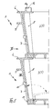
- the transport boxes shown in the figures, generally designated 1, are rectangular when viewed from above, that is to say they are provided with two longer side walls 2 and two shorter side walls 3 and with a bottom 4, the side walls 2 and 3 being slightly conical to the bottom 4 to enable stacking one inside the other and have at their upper free end a peripheral edge bead 5, which is in the empties transport position on the upper edge 6 of the Adjusts adjacent box, such as that shown in Fig. 2.
- the transition corners between the side walls 2 and 3 each have a push-through recess 7 in the bottom region, through which a stack support, generally designated 8, can be pushed inwards.
- a stack support generally designated 8
- the box 1 in the bottom area of these stack supports is equipped with an approximately H-shaped groove 9 or with inwardly pointing plug-in webs 10 which are overlapped by a plug-in foot 11 of the stack support 8, the plug-in foot 11 is equipped with a locking catch 12 which, in the inserted position, lies behind the webs 10 of the insertion groove 9, for example as shown in FIG. 4. An unwanted loosening of the stack support 8 is therefore no longer possible.
- a film hinge 13 shown exaggerated in FIG. 4 is provided, such that the stack supports 8 can be lowered from the position of the stack position shown in FIG. 1 into the position of the empties transport position shown in FIG. 2.
- the area of the stack supports 8 opposite the plug-in foot is designed as a receptacle 16 for the foot area of a further transport box to be stacked above it, at least one of the side walls 16a can already be conical in order to exert a certain fixing pressure to support the catch 15 when stacked one above the other.
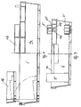
- FIG. 8 a box arranged above it is also shown in torn form in the stacked position, left half of the figure and in the transport position, right half of the figure.
- the lower box is labeled 1a and the upper box 1b.
- the clamping catch 15 ' is here equipped with two horizontally snapping lateral clamping webs 15a and 15b in order to ensure lateral guidance of the stack support 8'.
- the stack sides 8 ' are connected to one another in pairs here via a handling or folding web 17.
- the described exemplary embodiments of the invention can be modified in many ways without departing from the basic idea.
- the The plug-in foot 11 can be equipped with an end plate or end cap which is in contact with the walls 2 or 3 and which is at least tight for trickle material, in extreme cases a liquid-tight cover can be provided here.
- a catch can also be provided which lies on the outside over the edge 6 of the box in the stacking position.
- the stack supports can also be inserted with their support feet from above into corresponding recesses in the box bottom, so that the wall recesses 7 and 7 'are unnecessary and.
Abstract
Description
Die Erfindung richtet sich auf einen stapelbaren Transportkasten mit aus einer Stapelposition in eine Leergutstapelposition schwenkbaren Stapelstützen zur Stapelung übereinander in der Guttransportlage und zur Stapelung bereichsweise ineinander in der Leerguttransportlage.The invention is directed to a stackable transport box with stack supports which can be pivoted from a stacking position into an empties stacking position for stacking one above the other in the goods transport position and for stacking in one another in the empties transport position.
Es gibt eine Reihe von Einsatzzwecken, in denen derartige Transportkästen mit Gütern gefüllt transportiert werden und als Leergut zurück zum Füllort bewegt werden müssen. Um beim Leerguttransport Raum zu sparen, ist es bekannt, derartige Transportkästen nicht etwa um eine Mittelachse symmetrisch auszubilden, sondern in einer derartigen Weise unsymmetrisch mit Vor- und Rücksprüngen auszubilden, daß in einer Position die ins Kasteninnere weisenden Vorsprünge eine Stapelung möglich machen, während bei der in der Ebene um 180o gedrehten Position die Vorsprünge in korrespondierende Rücksprünge fluchten und so die leeren Kästen ineinander gestapelt werden können. Solche Kästen zeigt beispielsweise die US-PS 3 734 341 oder DE-U-86 27 458.There are a number of uses in which such transport boxes are transported filled with goods and have to be moved back to the filling location as empties. In order to save space in the transport of empties, it is known not to design such transport boxes symmetrically about a central axis, but to design them asymmetrically with projections and recesses in such a way that the projections pointing into the box interior make stacking possible in one position, while at the positions rotated in the plane by 180 o align the projections in corresponding recesses and so the empty boxes can be stacked one inside the other. Such boxes are shown, for example, in US Pat. No. 3,734,341 or DE-U-86 27 458.
Es ist auch bekannt, getrennte Bauteile zu verwenden, um eine Hochstapelung zu ermöglichen, die im Leerguttransport abgenommen werden können, um ein Ineinanderstapeln der Kästen zu ermöglichen. Steckbare Eckverbindungselemente zeigt beispielsweise DE-U-88 10 525, einen Aufsteckrahmen zeigt DE-U-90 10 460.It is also known to use separate components to enable stacking, which can be removed in the empties transport, to stack the boxes one inside the other to enable. Plug-in corner connection elements are shown, for example, by DE-U-88 10 525, and a push-on frame is shown by DE-U-90 10 460.
Einen gattungsgemäßen stapelbaren Behälter zeigt die DE-A-20 07 788. Dort sind nach außen ausschwenkbare federbelastete Trägerecken offenbart, die als Stapelstützen dienen und in der Leerlage in das Behälterinnere in entsprechende Taschen eingeschwenkt werden.DE-A-20 07 788 shows a generic stackable container. There, spring-loaded carrier corners which can be swung outward are disclosed, which serve as stack supports and are swung into corresponding pockets in the empty position in the interior of the container.
Ein Problem der weiter oben beschriebenen, sogenannten Wendekästen besteht darin, daß diese ganz exakt aufeinander abgestimmt sein müssen, d.h. verwenden unterschiedliche Verbraucher Wendekästen unterschiedlicher Produktionen, ist häufig ein Zusammenstapeln dieser Kästen nicht mehr gewährleistet. Die Stapelung dieser Wendekästen ist im übrigen in der Vollstapelung nur soweit möglich, wie es die obere Randbegrenzung der Kästen ermöglicht, d.h. im Inneren kann sich nur eine solche Transportkastenfüllung befinden, die den Rand nicht überragt. Dies ist aber häufig z.B. bei lebenden Pflanzen der Fall, so daß man in solchen Fällen zu Verlängerungsstücken greift, wie etwa die zuvor beschriebenen steckbaren Eckverbindungselemente. Derartige lose Elemente haben den Nachteil, daß sie verlorengehen können und dann am Einsatzort nicht mehr zur Verfügung stehen.A problem with the so-called reversing boxes described above is that they have to be perfectly coordinated with one another, ie if different consumers use reversing boxes of different productions, it is often no longer possible to stack these boxes together. The stacking of these turning boxes is only possible in full stacking as far as the upper edge of the boxes allows, ie inside there can only be a transport box filling that does not protrude beyond the edge. However, this is often the case, for example, with live plants, so that extension pieces are used in such cases, such as the plug-in corner connection elements described above. Loose elements of this type have the disadvantage that they can get lost and are then no longer available at the place of use.
Aufgabe der Erindung ist die Schaffung einer Lösung, mit der zum einen aufwendige Kastenformen, wie bei den Wendekästen, entbehrlich gemacht werden, was im Regelfalle auch die Herstellungskosten reduziert, zum anderen der Verlust von Stapelhilfsmitteln vermieden wird.The task of the invention is to create a solution which, on the one hand, eliminates the need for complex box shapes, such as the reversible boxes, which generally also reduces the production costs and, on the other hand, prevents the loss of stacking aids.
Mit einem stapelbaren Transportkasten der eingangs bezeichneten Art wird diese Aufgabe gemäß der Erfindung dadurch gelöst, daß die Stapelstützen mit einem am Kastenboden fixierbaren Steckfuß und einem daran mittels Filmscharniere od. dgl. befestigten Stützkörper mit einem Aufnahmekopfbereich für den Boden eines darüber gestapelten Kastens versehen sind, wobei die Stapelstützen auf den Kastenboden aus der Stapelposition in eine Leerguttransportposition schwenkbar sind.With a stackable transport box of the type mentioned at the outset, this object is achieved according to the invention in that the stack supports are provided with a plug-in foot which can be fixed to the bottom of the box and a support body fastened thereto by means of film hinges or the like, with a receiving head region for the bottom of a box stacked above it. the stack supports being pivotable onto the box floor from the stacking position into an empties transport position.
Diese mit dem Kasten verbundenen Stapelstützen unterliegen nicht der Gefahr, daß sie verlorengehen können, sie werden in der Stapellage hochgeschwenkt und bieten damit die Auflager für den darüber befindlichen Stapel, in der Leergutposition werden sie abgesenkt, die Kästen können daher ineinandergestapelt werden.These stack supports connected to the box are not subject to the risk of being lost, they are swung up in the stack position and thus provide the supports for the stack above them, in the empties position they are lowered, the boxes can therefore be stacked one inside the other.
Ausgestaltungen der Erfindung ergeben sich aus den Unteransprüchen:
Die Fixierung dieser Stapelstützen kann einmal dadurch erfolgen, daß im Übergangsbereich vom Kastenboden zur Kastenwandfläche eine Durchstecköffnung für die Stapelstütze und Stecknuten bzw. Steckstege zur Aufnahme des Fußes vorgesehen sind, wobei die Stapelstützen mit einer Raste zum Verrasten an bzw. in der Kastenwand in der hochgeschwenkten Lage ausgerüstet sind.Embodiments of the invention result from the subclaims:
The fixation of these stack supports can be done by providing a through opening in the transition area from the box floor to the box wall surface for the stack support and plug-in grooves or plug-in webs for receiving the foot, the stack supports having a catch for latching onto or in the box wall in the swiveled-up position Location are equipped.
Werden die Stapelstützen in der Nähe der Übergangsecken der kürzeren Seitenwände zu den längeren Seitenwänden angebracht, kann deren Länge deutlich über derjenigen der Wandhöhe des Transportkastens selbst liegen, im extremsten Falle dann, wenn in den gegenüberliegenden Seiten die Stapelstützen nicht fluchtend, sondern nebeneinander angeordnet sind, kann die gesamte Bodenlänge als Länge für die Stapelstützen ausgenutzt werden.If the stack supports are attached near the transition corners of the shorter side walls to the longer side walls, their length can be significantly greater than that of the wall height of the transport box itself, in the most extreme case if the stack supports are not aligned but side by side on the opposite sides, the entire floor length can be used as the length for the stack supports.
Die Erfindung ist nachstehend anhand der Zeichnung beispielsweise näher erläutert. Diese zeigt in
- Fig. 1
- einen Teilschnitt durch den Eckbereich zweier übereinandergestapelter Kästen,
- Fig. 2
- in gleicher Darstellungsweise den Eckbereich mit ineinander gestapelten Kästen,
- Fig. 3
- eine Aufsicht auf eine Kastenecke etwa gemäß Pfeil III in Fig. 1 ohne eingesteckte Stapelstütze,
- Fig. 4
- eine vergrößerte Teildarstellung des Fußbereiches einer Stapelstütze,
- Fig. 5
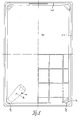
- eine Aufsicht auf einen Stapelkasten mit einer Stapelecke in der abgesenkten Lage sowie einer teilweisen Unteransicht,
- Fig. 6 und 7
- Seitenansichten bzw. Schnitte eines Stapelkastens sowie in
- Fig. 8 und 9
- Seitenansichten bzw. Schnitte durch ein weiteres Ausführungsbeispiel jeweils in verkleinertem Maßstab gemäß Maßstab Fig. 5.
- Fig. 1
- a partial section through the corner area of two stacked boxes,
- Fig. 2
- the corner area with boxes stacked one inside the other,
- Fig. 3
- 2 shows a top view of a box corner approximately according to arrow III in FIG. 1 without a stack support inserted,
- Fig. 4
- an enlarged partial view of the foot area of a stacking support,
- Fig. 5
- a top view of a stacking box with a stacking corner in the lowered position and a partial bottom view,
- 6 and 7
- Side views or sections of a stacking box as well as in
- 8 and 9
- Side views or sections through a further exemplary embodiment in each case on a reduced scale according to the scale of FIG. 5.
Die in den Figuren dargestellte, allgemein mit 1 bezeichneten Transportkästen sind in Aufsicht rechteckig, d.h. mit zwei längeren Seitenwänden 2 und zwei kürzeren Seitenwänden 3 sowie mit einem Boden 4 versehen, wobei zur Ermöglichung des Ineinanderstapelns die Seitenwände 2 und 3 geringfügig konisch zum Boden 4 verlaufen und an ihrem oberen freien Ende einen umlaufenden Randwulst 5 aufweisen, der sich in der Leerguttransportlage auf die obere Randkante 6 des Nachbarkastens auflegt, etwa wie sich dies aus Fig. 2 ergibt.The transport boxes shown in the figures, generally designated 1, are rectangular when viewed from above, that is to say they are provided with two
Bei dem in den Fig. 1 bis 7 dargestellten Beispiel weisen die Übergangsecken zwischen den Seitenwänden 2 und 3 im Bodenbereich je eine Durchsteckausnehmung 7 auf, durch die nach innen eine allgemein mit 8 bezeichnete Stapelstütze durchsteckbar ist. Wie sich insbesondere aus Fig. 3 ergibt, ist im Bodenbereich der Kasten 1 bei diesen Stapelstützen mit einer etwa H-förmigen Nut 9 bzw. mit nach innen weisenden Steckstegen 10 ausgerüstet, die von einem Steckfuß 11 der Stapelstütze 8 übergriffen werden, wobei der Steckfuß 11 mit einer Sperraste 12 ausgerüstet ist, die sich in der Einstecklage hinter die Stege 10 der Einstecknut 9 legt, etwa wie sich dies aus Fig. 4 ergibt. Ein ungewolltes Lösen der Stapelstütze 8 ist daher nicht mehr möglich. Im Übergangsbereich von Steckfuß 11 zur Stapelstütze 8 ist ein in Fig. 4 übertrieben dargestelltes Filmscharnier 13 vorgesehen, derart, daß die Stapelstützen 8 aus der in Fig. 1 dargestellten Stellung der Stapellage in die in Fig. 2 dargestellte Stellung der Leerguttransportlage abgesenkt werden können.In the example shown in FIGS. 1 to 7, the transition corners between the
Zur Fixierung der Stapelstütze 8 an den Seitenwänden 2 bzw. 3 sind diese mit einer kleinen Fixierausnehmung 14 ausgerüstet, in die eine Raste 15 einer Stapelstütze 8 eingreifen kann, wie sich dies aus Fig. 1 ergibt.To fix the
Der dem Steckfuß gegenüberliegende Bereich der Stapelstützen 8 ist als Aufnahme 16 für den Fußbereich eines darüber zu stapelnden weiteren Transportkastens ausgebildet, wenigstens eine der Seitenwände 16a kann bereits konisch ausgebildet sein, um beim Übereinanderstapeln einen gewissen Fixierdruck zur Unterstützung der Raste 15 auszuüben.The area of the stack supports 8 opposite the plug-in foot is designed as a
In den Fig. 8 und 9 ist ein geringfügig abgewandeltes Ausführungsbeispiel dargestellt. Hier sind die Stapelstützen 8' nicht in den Kastenecken vorgesehen, sondern in deren Nähe an den kürzeren Seitenwänden 3'. In Fig. 8 ist darüber hinaus ausrißweise jeweils ein darüber angeordneter Kasten in Stapellage, linke Figurenhälfte, und in der Transportlage, rechte Figurenhälfte, dargestellt. Hier ist der untere Kasten mit 1a bezeichnet und der obere Kasten mit 1b.8 and 9, a slightly modified embodiment is shown. Here the stack supports 8 'are not provided in the box corners, but in the vicinity of the shorter side walls 3'. In FIG. 8, a box arranged above it is also shown in torn form in the stacked position, left half of the figure and in the transport position, right half of the figure. Here the lower box is labeled 1a and the upper box 1b.
Die Klemmraste 15' ist hier mit zwei horizontal schnappenden seitlichen Klemmstegen 15a und 15b ausgerüstet, um eine seitliche Führung der Stapelstütze 8' sicherzustellen. Die Stapelseiten 8' sind hier paarweise über einen Handhabungs- bzw. Klappsteg 17 miteinander verbunden.The clamping catch 15 'is here equipped with two horizontally snapping lateral clamping webs 15a and 15b in order to ensure lateral guidance of the stack support 8'. The stack sides 8 'are connected to one another in pairs here via a handling or folding
Natürlich sind die beschriebenen Ausführungsbeispiele der Erfindung noch in vielfacher Hinsicht abzuändern, ohne den Grundgedanken zu verlassen. So kann beispielsweise der Steckfuß 11 mit einer sich von außen an die Wände 2 bzw. 3 anlegenden Abschlußplatte oder Abschlußkappe ausgerüstet sein, die wenigstens dicht für Rieselgut ausgebildet ist, im Extremfalle kann hier eine flüssikeitsdichte Abdeckung vorgesehen sein. Bei vergleichsweise hohen Stapelstützen kann auch eine Raste vorgesehen sein, die sich außen über den Rand 6 des Kastens in der Stapellage legt. Die Stapelstützen können mit ihren Stützfüßen auch von oben in entsprechende Ausnehmungen im Kastenboden einsteckbar sein, so daß die Wandausnehmungen 7 bzw. 7' entbehrlich sind u. dgl. mehr.Of course, the described exemplary embodiments of the invention can be modified in many ways without departing from the basic idea. For example, the The plug-in
Claims (6)
dadurch gekennzeichnet,
daß die Stapelstützen (8) mit einem am Kastenboden (4) fixierbaren Steckfuß (11) und einem daran mittels Filmscharniere (13) od. dgl. befestigten Stützkörper mit einem Aufnahmekopfbereich (16) für den Boden (4) eines darüber gestapelten Kastens (1) versehen sind, wobei die Stapelstützen (8) auf den Kastenboden (4) aus der Stapelposition (Fig. 1) in eine Leerguttransportposition (Fig. 2) schwenkbar sind.Stackable transport box with stack supports (8) which can be pivoted from a stacking position into an empties stacking position for stacking one above the other in the goods transport position and for stacking in one another in the empties transport position,
characterized,
that the stack supports (8) with a plug-in foot (11) which can be fixed to the box base (4) and a support body fastened to it by means of film hinges (13) or the like with a receiving head area (16) for the bottom (4) of a box (1 ) are provided, the stack supports (8) being pivotable onto the box base (4) from the stacking position (FIG. 1) into an empties transport position (FIG. 2).
dadurch gekennzeichnet,
daß die Stapelstützen (8) mit einer Raste (15) zum Verrasten an bzw. in der Kastenwand (2,3) ausgerüstet sind.Transport box according to claim 1,
characterized,
that the stack supports (8) are equipped with a catch (15) for locking on or in the box wall (2, 3).
dadurch gekennzeichnet,
daß im Übergangsbereich vom Kastenboden (4) zur Kastenwandfläche (2,3) eine Durchstecköffnung (7) für die Stapelstütze (8) und Stecknuten (9) bzw. Steckstegen (10) zur Aufnahme des Fußes vorgesehen sind.Transport box according to claim 1 or 2,
characterized,
that in the transition area from the box floor (4) to the box wall surface (2,3) a push-through opening (7) for the stack support (8) and plug-in grooves (9) or plug-in webs (10) are provided for receiving the foot.
dadurch gekennzeichnet,
daß die Stapelstützen (8) in den Übergangsecken der Kastenwandflächen vorgesehen sind.Transport box according to one of the preceding claims,
characterized,
that the stack supports (8) are provided in the transition corners of the box wall surfaces.
dadurch gekennzeichnet,
daß die Stützenlänge der Stapelstützen (8) größer ist als die Wandhöhe des Transportkastens (1).Transport box according to one of the preceding claims,
characterized,
that the support length of the stack supports (8) is greater than the wall height of the transport box (1).
dadurch gekennzeichnet,
daß die Kopfbereiche (16) der Stapelstützen (8) mit geringfügig nach außen weisenden Innenflächen (16a) zur Aufnahme der korrespondierend ausgebildeten Fußbereiche des darüber gestapelten Kastens (1) ausgerüstet sindTransport box according to one of the preceding claims,
characterized,
that the head areas (16) of the stack supports (8) are equipped with slightly outwardly facing inner surfaces (16a) for receiving the correspondingly designed foot areas of the box (1) stacked above them
Applications Claiming Priority (2)
| Application Number | Priority Date | Filing Date | Title |
|---|---|---|---|
| DE19924228819 DE4228819A1 (en) | 1992-08-29 | 1992-08-29 | Stackable transport box |
| DE4228819 | 1992-08-29 |
Publications (2)
| Publication Number | Publication Date |
|---|---|
| EP0585575A2 true EP0585575A2 (en) | 1994-03-09 |
| EP0585575A3 EP0585575A3 (en) | 1995-04-12 |
Family
ID=6466745
Family Applications (1)
| Application Number | Title | Priority Date | Filing Date |
|---|---|---|---|
| EP93111340A Withdrawn EP0585575A3 (en) | 1992-08-29 | 1993-07-15 | Stackable carrying case. |
Country Status (2)
| Country | Link |
|---|---|
| EP (1) | EP0585575A3 (en) |
| DE (1) | DE4228819A1 (en) |
Cited By (3)
| Publication number | Priority date | Publication date | Assignee | Title |
|---|---|---|---|---|
| GB2289881A (en) * | 1994-06-01 | 1995-12-06 | Richardson Limited | Cullet delivery container |
| GB2331980A (en) * | 1997-12-03 | 1999-06-09 | Mckechnie Uk Ltd | Stacking container |
| US7128234B2 (en) | 1998-06-16 | 2006-10-31 | Rehrig Pacific Company | Stackable low depth bottle case |
Families Citing this family (6)
| Publication number | Priority date | Publication date | Assignee | Title |
|---|---|---|---|---|
| DE4438983A1 (en) * | 1994-10-31 | 1996-05-02 | Thyssen Polymer Gmbh | Container with symmetrical ribs for stacking |
| GB9516739D0 (en) * | 1995-08-16 | 1995-10-18 | Mckechnie Uk Ltd | Stacking and nesting containers |
| GB2318346B (en) * | 1995-08-16 | 1999-09-29 | Mckechnie Uk Ltd | Stacking and nesting containers |
| JP3223180B2 (en) * | 1999-06-09 | 2001-10-29 | 豊田通商株式会社 | Through container |
| DE10333066A1 (en) * | 2003-07-21 | 2005-03-03 | Franz Stanislav Bartos | Container, e.g. box or bucket to transport and store goods has fold-down corners to permit stacking of full containers without damaging contents |
| EP2390199B1 (en) | 2010-05-27 | 2013-07-10 | Rehrig Pacific Company | Collapsible dual height stacking container |
Citations (4)
| Publication number | Priority date | Publication date | Assignee | Title |
|---|---|---|---|---|
| FR2077219A1 (en) * | 1970-01-19 | 1971-10-22 | Bottiger Et Co | |
| US3648909A (en) * | 1970-08-26 | 1972-03-14 | Bishop Wisecarver Corp | Carrying tray |
| DE2154337A1 (en) * | 1971-11-02 | 1973-05-10 | Boettiger & Co | FRUIT AND VEGETABLE FOAM |
| DE3741350A1 (en) * | 1987-12-07 | 1989-06-15 | Stabernack Gmbh Gustav | Stackable tray |
Family Cites Families (1)
| Publication number | Priority date | Publication date | Assignee | Title |
|---|---|---|---|---|
| DE2007788A1 (en) * | 1970-02-20 | 1971-08-26 | Westform Plastikwerke GmbH, 5256 Hommench | Stackable container |
-
1992
- 1992-08-29 DE DE19924228819 patent/DE4228819A1/en not_active Withdrawn
-
1993
- 1993-07-15 EP EP93111340A patent/EP0585575A3/en not_active Withdrawn
Patent Citations (4)
| Publication number | Priority date | Publication date | Assignee | Title |
|---|---|---|---|---|
| FR2077219A1 (en) * | 1970-01-19 | 1971-10-22 | Bottiger Et Co | |
| US3648909A (en) * | 1970-08-26 | 1972-03-14 | Bishop Wisecarver Corp | Carrying tray |
| DE2154337A1 (en) * | 1971-11-02 | 1973-05-10 | Boettiger & Co | FRUIT AND VEGETABLE FOAM |
| DE3741350A1 (en) * | 1987-12-07 | 1989-06-15 | Stabernack Gmbh Gustav | Stackable tray |
Cited By (5)
| Publication number | Priority date | Publication date | Assignee | Title |
|---|---|---|---|---|
| GB2289881A (en) * | 1994-06-01 | 1995-12-06 | Richardson Limited | Cullet delivery container |
| GB2331980A (en) * | 1997-12-03 | 1999-06-09 | Mckechnie Uk Ltd | Stacking container |
| US6145664A (en) * | 1997-12-03 | 2000-11-14 | Mckechnie Uk Limited | Container |
| GB2331980B (en) * | 1997-12-03 | 2002-03-20 | Mckechnie Uk Ltd | Load transfer for multiple-height stacking |
| US7128234B2 (en) | 1998-06-16 | 2006-10-31 | Rehrig Pacific Company | Stackable low depth bottle case |
Also Published As
| Publication number | Publication date |
|---|---|
| DE4228819A1 (en) | 1994-03-03 |
| EP0585575A3 (en) | 1995-04-12 |
Similar Documents
| Publication | Publication Date | Title |
|---|---|---|
| DE3121243C2 (en) | ||
| DE3223282C2 (en) | ||
| EP2582585B1 (en) | Transporting container | |
| EP0301417B1 (en) | Single container for assembly into a multiple container | |
| EP0453724A2 (en) | Multi-part recipient | |
| EP0585575A2 (en) | Stackable carrying case | |
| AT1499U1 (en) | TRANSPORT SPACER TABLET FOR BOTTLES | |
| EP0025510A1 (en) | Transport and/or storage container, especially of plastic material | |
| EP0705764A2 (en) | Container in the form of a crate | |
| DE4312842C2 (en) | Transport means made in one piece from plastic, in particular transport boxes, trays, pallets or the like. | |
| DE6603723U (en) | STACKABLE AND NESTABLE CONTAINER | |
| EP0818394B1 (en) | Plastic container,stackable by rotation method | |
| DE3909898C2 (en) | ||
| DE2000371A1 (en) | Connection piece for container or the like. | |
| DE4317300C1 (en) | Box-shaped plastic container which can be stacked and nested | |
| EP0698558A2 (en) | Stackable transportcontainer | |
| CH668404A5 (en) | SET OF STACKABLE RISKS IN PLASTIC FOR BOTTLES, ESPECIALLY WINE BOTTLES. | |
| EP0440844A1 (en) | Carrying crates with means to detachably connect carrying crates | |
| EP0265581A1 (en) | Tapered stackable box | |
| DE8419856U1 (en) | Stackable pallet for the transport of can lids | |
| DE8526839U1 (en) | Shopping venture | |
| EP1319603B1 (en) | Box-type container | |
| EP0541851B1 (en) | Stackable bottle crate made of plastic | |
| DE3530113A1 (en) | Pallet for conical containers | |
| EP0694482B1 (en) | Rectangular transport tray |
Legal Events
| Date | Code | Title | Description |
|---|---|---|---|
| PUAI | Public reference made under article 153(3) epc to a published international application that has entered the european phase |
Free format text: ORIGINAL CODE: 0009012 |
|
| AK | Designated contracting states |
Kind code of ref document: A2 Designated state(s): AT BE CH DE DK FR GB IE LI NL SE |
|
| PUAL | Search report despatched |
Free format text: ORIGINAL CODE: 0009013 |
|
| AK | Designated contracting states |
Kind code of ref document: A3 Designated state(s): AT BE CH DE DK FR GB IE LI NL SE |
|
| STAA | Information on the status of an ep patent application or granted ep patent |
Free format text: STATUS: THE APPLICATION IS DEEMED TO BE WITHDRAWN |
|
| 18D | Application deemed to be withdrawn |
Effective date: 19951013 |