EP0207777A2 - Mécanisme de charnière - Google Patents
Mécanisme de charnière Download PDFInfo
- Publication number
- EP0207777A2 EP0207777A2 EP86305082A EP86305082A EP0207777A2 EP 0207777 A2 EP0207777 A2 EP 0207777A2 EP 86305082 A EP86305082 A EP 86305082A EP 86305082 A EP86305082 A EP 86305082A EP 0207777 A2 EP0207777 A2 EP 0207777A2
- Authority
- EP
- European Patent Office
- Prior art keywords
- sleeve
- rod
- hinge mechanism
- bearing surface
- sleeve member
- Prior art date
- Legal status (The legal status is an assumption and is not a legal conclusion. Google has not performed a legal analysis and makes no representation as to the accuracy of the status listed.)
- Granted
Links
Images
Classifications
-
- B—PERFORMING OPERATIONS; TRANSPORTING
- B60—VEHICLES IN GENERAL
- B60J—WINDOWS, WINDSCREENS, NON-FIXED ROOFS, DOORS, OR SIMILAR DEVICES FOR VEHICLES; REMOVABLE EXTERNAL PROTECTIVE COVERINGS SPECIALLY ADAPTED FOR VEHICLES
- B60J3/00—Antiglare equipment associated with windows or windscreens; Sun visors for vehicles
- B60J3/02—Antiglare equipment associated with windows or windscreens; Sun visors for vehicles adjustable in position
- B60J3/0204—Sun visors
- B60J3/0213—Sun visors characterised by the mounting means
- B60J3/0265—Attachments of sun visors to mounting means including details of sun visor bearing member regulating the rotational friction on the support arm
Definitions
- This invention relates to a hinge mechanism suitable for supporting a vehicle mounted sun visor.
- Sun visors for vehicles are usually provided with a support arm extending from the vehicle structure and various means have been proposed in the past for attaching the visor to the support arm in such a way that it is frictionally held so that it can be held in a stored postion, sometimes with a detent operative at this stored position, for movement to any one of a number of positions where it is effective to shade the eyes of the vehicle driver or passenger from sunlight.
- Previously employed designs for such hinge mechanisms have included a sleeve member engaged upon a rod member with the required friction provided by a spring clip engaged around the sleeve member. Often a portion of the spring clip is formed to extend through the sleeve and engage the rod member, which is manufactured with a "flat" portion on its surface, to provide a detent at the sun visor's stored position. Examples of this type of hinge mechanism are disclosed in British Patent No 1 534 282 and published European Patent Application 0 053 529.
- hinge mechanisms suffer from two distinct disadvantages: firstly the hinge mechanisms require the manufacture and assembly of at least three, sometimes complex, components at a commensurately high cost, and secondly the finished hinges are prone to rattle as a result of the number of components employed and the necessity to form some of the components from metal.
- the design proposed in GB 1 422 368 was intended to overcome the problems of the earlier two-piece design by incorporating a gap in the sleeve or bearing member of the hinge described in GB 1 395 689.
- the plastics forming the sleeve or bearing member tend to flow under load and the gap opens up, thereby reducing the grip of the sleeve or bearing member upon the rod to below an acceptable level.
- the corner formed where the flat portion meets the curved portion of the rod catches in the gap as the rod is rotated, pulling the gap apart and thereby exacerbating the gap's tendency to open in use.
- a hinge mechanism comprising a sleeve member defining an inwardly facing bearing surface and a rod member dimensioned to fit in the sleeve memeber in engagement with the bearing surface, by providing a hinge mechanism in which the sleeve member is resiliently flexible but substantially inextensible, at least one recess is formed in the bearing surface, the rod member is provided with a projection shaped to be engageable in the recess and is an interference fit in the sleeve member with the projection located in the recess, the rod member being rotatable in the sleeve member by causing only resilient deformation of the latter.
- an interference fit it is meant that when the sleeve and rod members are assembled, a slight resilient distortion of the sleeve member occurs.
- the hinge mechanism of the present invention includes the following:-The hinge mechanism only comprises two components, at least one of which, the sleeve, may be readily formed from plastics materials by injection moulding techniques; the hinge is totally rattle proof in use and; the grip of the sleeve upon the rod does not degrade with use.
- the recess is in the form of a longitudinal groove of rounded cross-section and the rod is substantially cylindrical with the projection provided by an elongate cam-lobe shaped to be engageable in the longitudinal groove to provide a detent position.
- the bearing surface has a generally cylindrical form when the sleeve member is relaxed.
- the rod has a larger radius portion having a radius greater than the radius of the cam lobe and less than the radius of the relaxed bearing surface, which larger radius portion extends over a length of arc sufficient to span the groove in a circumferential direction. Since the sleeve is a complete cylinder, where ever the rod may be in the sleeve there are always forces acting to restore a distorted portion of the sleeve to the original generally cylindrical form.
- An advantage of this embodiment is that the forces exerted upon the cam lobe by the sleeve are exerted along its entire length, and the tendency of either component of the hinge to wear is reduced. Furthermore if the hinge is left in a position where the cam-lobe is not in the groove, the tendency for the lobe to leave a permanent indentation in the bearing surface is minimised. This results both from the length of the cam-lobe and the fact that any such indentation is stretched out when the lobe is rotated away from it.
- the rod has only one elongate cam-lobe.
- the small radius of the cam-lobe is held in the groove by the pressure exerted on the large radius portion of the rod by the bearing surface of the sleeve member, which is distorted by virture of the two components having an interference fit.
- the choice of radii for the various components and the length of arc of the larger radius component of the rod allows the rod to rotate smoothly within the sleeve while without giving any detent action except when the cam-lobe falls into the groove.
- the sleeve member is reinforced in the vicinity of the groove and this reinforcement may be provided by a lug extending from the sleeve, which lug is adapted to engage a first component to be hinged, possibly a sun visor, the rod being provided with means for engaging a second component to be hinged, for example a vehicle body.
- the rod is provided with a plurality of elongate cam-lobes arranged around its periphery and the sleeve member is provided with a plurality of recesses in the bearing surface thereof, the number of recesses being different to the number of cam-lobes. For example, there may be four equally spaced cam-lobes on the rod and three equally spaced recesses in the bearing surface. This will then provide a detent position every 30 0 of rotation.
- Hinge mechanisms in accordance with the present invention are especially suitable to having their sleeve member formed from a plastics material of the kind generally referred to as "engineering plastics", such acetals, polycarbonates, PBT or nylon.
- engineing plastics such as acetals, polycarbonates, PBT or nylon.
- Such plastic does not stretch appreciably, unless overloaded, however it is readily resiliently distorted.
- a sleeve member of the present invention will be distorted by the rotation of a rod member therein, however it will maintain the same peripheral or circumferential length and thus put considerable pressure on the support arm.
- the present invention provides a vehicle sun visor including a hinge mechanism in accordance with the first aspect of the present invention.
- the body of such a sun visor is engaged with a lug extending from the sleeve and the rod member is provided with means for engagement with a vehicle body.
- the sun visor incorporates a flap for covering or carrying a mirror, which flap is hinged to the visor body by a hinge in accordance with the first aspect of this invention.
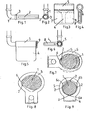
- a support arm 1 comprises a generally L-shaped arm of circular cross section, the top end of which is for support from the roof of a vehicle by a swivel or ball joint (not shown).
- the horizontal portion of the arm 1 is provided with an elongated projection 2 which has the general form of a cam-lobe, as shown in Figure 2.
- a stop shoulder 3 is also provided.
- the other part of the hinge comprises a plastic moulding 4, as shown in Figures 3 and 4, and this has an upper part in the form of a tubular bearing sleeve 5 which has a recess 6 arranged to mate with the projection of the arm 1.
- the remaining flat part of the moulding 4 has a pair of internal recesses 7 and 8 into which are inserted the respective ends of a wire frame which forms part of and supports the visor from the moulding 4. These wire ends are bent to fit around the curved portions of the recesses shown in dashed lines in Figure 3.
- the wires may be held in position in the moulding 4 by staking or by insertion of plugs or by hot pressing of the material of the moulding, if it is a thermoplastic material.
- the moulding 4, together with the visor (not shown) is assembled on to the support arm and its projection 2, the sizing of the sleeve portion being such that the moulding 4 can be assembled on to the arm by a push or interference fit.
- the arm 1 will ordinarily be of metal, maybe tubular in order to provide a passage for electrical conductors to power a lamp for a vanity mirror in the visor, a tab 9 may form part of the moulding 4 arranged so as to cover the end of the arm 1 to comply with safety regulations.
- FIG. 7 and 8 The fit and operation of the hinge is shown in more detail in Figures 7 and 8 where the arm 1, shown in this case for clarity as a solid rod, has its projection in the form of a cam-lobe.
- the sleeve 5 is shown in its initial relaxed condition in dashed lines, from which it will be observed that its internal profile is circular but with a recess 6 corresponding in shape to the tip of the cam-lobe.
- the sleeve 5 is an interference fit on the arm 1 and this is shown in exaggerated form so that it can be seen that when assembled the inner profile of the sleeve 5 becomes distorted so as to conform to the circular portion of the arm 1 and the sleeve as a whole is constrained to adopt a somewhat oval configuration.
- FIG. 9 A further form of the invention is shown in Figure 9, which corresponds in general terms to Figure 8 of the first form of the invention.
- the arm 1 is in the form of a circular cross-section body having a number of projecting lobes 2 around its periphery.
- a moulding 4 again forms a support for frame wires forming a basis for the visor body (not shown) and has a generally circular profile sleeve 5 and this has a number of recesses, one of which is shown at 6a.
- the arrangement is such that, taking into account the extent to which all the projections 2 are raised from the surface of the arm 1, the inner profile of the sleeve 5 forms an interference fit with the arm 1 having one of the projections 2 in engagement with the recesses 6a.
- Further recesses 6b and 6c are provided at positions that do not coincide with any of the projections 2 while one of them is engaged with the recess 6a. They are however, equidistantly spaced and in this particular case there are four projections 2 and three recesses. It will be seen, therefore, that a number of detent positions is provided as the moulding 4 is rotated so as to being the projections 6b and 6c in turn into correspondence with successive projections 2.
- the arrangement of four projections and three recesses provides detent positions at 30° in the rotation of the sleeve 5 with respect to the arm 1. Other combinations of number of recesses and projections may be used to provide a larger or smaller number of positions.
- one or more additional detent positions can be provide either by having extra lobes or extra recesses, or both.
- an additional recess could be can be provided at approximately 180° so as to provide locked position for the visor both in its stored position and in the position where it is virtually flat against the windscreen.
- an extra detent position could be arranged in the example shown in Figure 9 by having an extra recess opposite the one in which the lobe 6a is located.
Applications Claiming Priority (2)
| Application Number | Priority Date | Filing Date | Title |
|---|---|---|---|
| GB8516896 | 1985-07-04 | ||
| GB08516896A GB2177057A (en) | 1985-07-04 | 1985-07-04 | Vehicle sun visor |
Publications (3)
| Publication Number | Publication Date |
|---|---|
| EP0207777A2 true EP0207777A2 (fr) | 1987-01-07 |
| EP0207777A3 EP0207777A3 (en) | 1987-10-28 |
| EP0207777B1 EP0207777B1 (fr) | 1990-11-07 |
Family
ID=10581760
Family Applications (1)
| Application Number | Title | Priority Date | Filing Date |
|---|---|---|---|
| EP86305082A Expired - Lifetime EP0207777B1 (fr) | 1985-07-04 | 1986-07-01 | Mécanisme de charnière |
Country Status (4)
| Country | Link |
|---|---|
| US (1) | US4734955A (fr) |
| EP (1) | EP0207777B1 (fr) |
| DE (1) | DE3675439D1 (fr) |
| GB (1) | GB2177057A (fr) |
Cited By (6)
| Publication number | Priority date | Publication date | Assignee | Title |
|---|---|---|---|---|
| WO1994000312A1 (fr) * | 1992-06-24 | 1994-01-06 | Fico I.T.M., S.A. | Dispositif de fixation pour pare-soleil de vehicules automobiles |
| FR2697479A1 (fr) * | 1992-11-05 | 1994-05-06 | Rockwell Abs France | Dispositif d'articulation de pare-soleil. |
| EP0621149A1 (fr) * | 1993-04-17 | 1994-10-26 | GEBR. HAPPICH GmbH | Pare-soleil pour véhicule |
| DE4315232A1 (de) * | 1993-05-07 | 1994-11-10 | Happich Gmbh Gebr | Lagervorrichtung, insbesondere für schwenkbar gelagerte Sonnenblenden von Fahrzeugen |
| DE4427445C1 (de) * | 1994-08-03 | 1995-12-14 | Happich Gmbh Gebr | Lagervorrichtung, insbesondere für schwenkbar gelagerte Sonnenblenden von Fahrzeugen |
| WO2010081030A1 (fr) * | 2009-01-09 | 2010-07-15 | Johnson Controls Technology Company | Ensemble charnière pour un composant de garniture intérieure de véhicule |
Families Citing this family (46)
| Publication number | Priority date | Publication date | Assignee | Title |
|---|---|---|---|---|
| JPH057629Y2 (fr) * | 1986-08-29 | 1993-02-25 | ||
| SE464400B (sv) * | 1986-11-20 | 1991-04-22 | Autopart Sweden Ab | Solskydd med spegelbelysning och svaenglucka |
| US4882807A (en) * | 1988-07-11 | 1989-11-28 | Prince Corporation | Armrest torque control |
| US4953259A (en) * | 1988-07-11 | 1990-09-04 | Prince Corporation | Armrest torque control |
| DE3833673A1 (de) * | 1988-10-04 | 1990-04-05 | Happich Gmbh Gebr | Sonnenblende fuer fahrzeuge |
| US4914781A (en) * | 1988-12-27 | 1990-04-10 | Maytag Corporation | Hinge assembly for a closure member |
| US5109573A (en) * | 1990-09-27 | 1992-05-05 | Smith Corona Corporation | Brake mechanism for a pivotable character display |
| JPH04203517A (ja) * | 1990-11-29 | 1992-07-24 | Toshiba Corp | 軸の枢着装置 |
| US5276945A (en) * | 1991-11-05 | 1994-01-11 | Shuji Matsumura | Hinge device having directional damping |
| US5255965A (en) * | 1992-02-13 | 1993-10-26 | Ting P. Chen | Waterproof stereo cover assembly with hinge providing multiple stop positions |
| US5406678A (en) * | 1993-07-22 | 1995-04-18 | General Clutch Corporation | Friction hinge |
| WO1995014842A1 (fr) * | 1993-11-24 | 1995-06-01 | General Clutch Corporation | Charniere a friction a element d'arret |
| US5645308A (en) * | 1995-08-29 | 1997-07-08 | Prince Corporation | Sliding visor |
| US5669107A (en) * | 1996-07-16 | 1997-09-23 | Lear Corporation | Friction detent apparatus for seat accessory |
| US5678880A (en) * | 1996-10-28 | 1997-10-21 | Keller; Lucius W. | Visor extender |
| US6010174A (en) | 1997-04-14 | 2000-01-04 | Lear Automotive Dearborn, Inc. | Sliding visor |
| US5966776A (en) * | 1997-05-07 | 1999-10-19 | Strawberry Corporation | Hinge device |
| DE19726536A1 (de) * | 1997-06-23 | 1998-12-24 | Daimler Benz Ag | Scharnier zum schwenkbaren Lagern eines Bauteils |
| US5933917A (en) * | 1998-01-06 | 1999-08-10 | Delta Electronics Inc. | Case with adjustable and positionable handle device |
| US6101676A (en) * | 1998-01-27 | 2000-08-15 | Dell Usa, L.P. | Adjustable clutch hinge assembly for portable computer |
| US6035491A (en) * | 1998-05-04 | 2000-03-14 | Hartigan; Michael J. | Hinge control mechanism for a foldable device |
| US6357128B1 (en) * | 1998-07-27 | 2002-03-19 | The Brunton Company | Low profile compass with removable protective cover and magnetic bull's eye alignment system |
| US6263543B1 (en) * | 1999-07-30 | 2001-07-24 | Avaya Technology Corp. | Self-latching hinge design |
| US6470532B2 (en) | 2000-02-29 | 2002-10-29 | Torqmaster, Inc. | Cam hinge with controlled friction for improved cam operation |
| US6584645B2 (en) * | 2000-09-18 | 2003-07-01 | Agostino Ferrari S.P.A. | Breaking device for furniture doors with a horizontal pivotal mounting |
| US6588062B2 (en) | 2001-09-11 | 2003-07-08 | Cema Technologies, Inc. | Spring loaded pop-up friction hinge assembly |
| DE10144994B4 (de) * | 2001-09-12 | 2010-01-28 | Dorma Gmbh + Co. Kg | Feststellvorrichtung für den Schwenkflügel einer Tür |
| US6951184B2 (en) * | 2003-01-16 | 2005-10-04 | Transpec, Inc. | Crossing control arm assembly |
| US7051404B2 (en) * | 2003-08-11 | 2006-05-30 | Craft, Inc. | Self-locking hinge |
| US20050211587A1 (en) * | 2004-03-26 | 2005-09-29 | Kun-Chen Chen | Tool bracket for storing tool bits |
| DE102004061999A1 (de) * | 2004-12-23 | 2006-07-06 | Robert Bosch Gmbh | Anordnung zur Schwenkung eines im Wesentlichen flachen Gehäuses einer elektronischen Vorrichtung |
| US20090173762A1 (en) * | 2005-05-12 | 2009-07-09 | Kun-Chieh Wang | Detachable Fastening Apparatus |
| TWM279160U (en) * | 2005-06-20 | 2005-10-21 | Shin Zu Shing Co Ltd | Horizontal type pivoting units |
| US7375279B2 (en) * | 2005-07-13 | 2008-05-20 | Kuan-Wei Chen | Waterproof cover for an audio system |
| US7667959B2 (en) * | 2005-12-20 | 2010-02-23 | Nokia Corp. | Foldable electronic device having double-axis hinge and locking spring |
| US7891055B1 (en) * | 2006-01-27 | 2011-02-22 | Gary Combs | Replacement hinge pin |
| TWI292860B (en) * | 2006-02-16 | 2008-01-21 | Asustek Comp Inc | A variable-torque rotation shaft with low weariness |
| US20110072620A1 (en) * | 2009-09-28 | 2011-03-31 | Cheng Uei Precision Industry Co., Ltd. | Hinge |
| US8959717B2 (en) * | 2012-03-12 | 2015-02-24 | Reell Precision Manufacturing Corporation | Circumferential strain rotary detent |
| TWM444022U (en) * | 2012-08-23 | 2012-12-21 | Dexin Corp | Cover-raisable electronic apparatus |
| DE102014215432B4 (de) * | 2014-08-05 | 2019-06-13 | Adient Luxembourg Holding S.À R.L. | Gesicherte Armlehne |
| US10081228B2 (en) * | 2016-11-08 | 2018-09-25 | Mahmoud Razzaghi | Car visor |
| US11046227B2 (en) | 2017-03-09 | 2021-06-29 | Illinois Tool Works Inc. | Assist grip assembly including a pivotal object hook |
| KR102055503B1 (ko) * | 2018-06-14 | 2019-12-12 | 주식회사 동원테크 | 자동차용 선바이저 |
| TWI657017B (zh) * | 2018-09-21 | 2019-04-21 | 美律實業股份有限公司 | 樞軸組件以及包含其之容器 |
| US11523681B2 (en) * | 2019-12-09 | 2022-12-13 | Inno-Sports Co., Ltd. | Frame and table having structure for reducing vibration |
Citations (3)
| Publication number | Priority date | Publication date | Assignee | Title |
|---|---|---|---|---|
| US2304223A (en) * | 1941-09-04 | 1942-12-08 | Reconstruction Finance Corp | Visor |
| FR2277268A1 (fr) * | 1974-07-06 | 1976-01-30 | Happich Gmbh Gebr | Palier d'articulation de volet, notamment pour pare-soleil de vehicules |
| FR2491403A1 (fr) * | 1980-10-06 | 1982-04-09 | Sacic | Dispositif d'articulation pour pare-soleil de vehicules |
Family Cites Families (16)
| Publication number | Priority date | Publication date | Assignee | Title |
|---|---|---|---|---|
| FR53529E (fr) * | 1944-02-17 | 1946-03-04 | Junkers & Co | Dispositif de sûreté pour installations de chauffage au gaz |
| US2458707A (en) * | 1946-02-23 | 1949-01-11 | Jacobs Co F L | Visor |
| FR1123335A (fr) * | 1955-03-08 | 1956-09-20 | Citroen Sa Andre | Pare-soleil |
| US3000049A (en) * | 1958-08-04 | 1961-09-19 | American Plastics Corp | Plastic hinge and method of making the same |
| FR80346E (fr) * | 1961-09-18 | 1963-04-12 | Happich Gmbh Gebr | Pare-soleil et procédé pour sa fabrication |
| SE367584B (fr) * | 1969-05-28 | 1974-06-04 | Happich Gmbh Gebr | |
| DE2226429C3 (de) * | 1972-05-31 | 1975-11-20 | Gebr. Happich Gmbh, 5600 Wuppertal | Sonnenblende mit einem Schwenklager, insbesondere für Fahrzeuge |
| FR2194585B1 (fr) * | 1972-08-02 | 1976-11-12 | Happich Gmbh Gebr | |
| US3872541A (en) * | 1974-04-15 | 1975-03-25 | Hager & Sons Hinge Mfg | Hinge capable of transmitting pressurized air |
| GB1534282A (en) * | 1975-11-04 | 1978-11-29 | Morgan Soft Trim Ltd | Sun visors |
| GB1560723A (en) * | 1977-06-13 | 1980-02-06 | Helmets Ltd | Visor assemblies |
| US4116514A (en) * | 1977-07-22 | 1978-09-26 | Lawrence Brothers, Inc. | Security hinge |
| IT8053530V0 (it) * | 1980-09-22 | 1980-09-22 | Lear Snc | Schermo parasole per autoveicoli del tipo orientabile con possibilita di regolazione del posizionamento |
| US4553797A (en) * | 1982-01-21 | 1985-11-19 | Prince Corporation | Mounting bracket |
| US4491899A (en) * | 1983-02-07 | 1985-01-01 | Prince Corporation | Visor cover assembly |
| US4580829A (en) * | 1983-12-27 | 1986-04-08 | Matheopoulos Paul C | Adjustable bidirectional vehicle visor |
-
1985
- 1985-07-04 GB GB08516896A patent/GB2177057A/en not_active Withdrawn
-
1986
- 1986-07-01 DE DE8686305082T patent/DE3675439D1/de not_active Expired - Fee Related
- 1986-07-01 EP EP86305082A patent/EP0207777B1/fr not_active Expired - Lifetime
- 1986-07-07 US US06/882,387 patent/US4734955A/en not_active Expired - Fee Related
Patent Citations (3)
| Publication number | Priority date | Publication date | Assignee | Title |
|---|---|---|---|---|
| US2304223A (en) * | 1941-09-04 | 1942-12-08 | Reconstruction Finance Corp | Visor |
| FR2277268A1 (fr) * | 1974-07-06 | 1976-01-30 | Happich Gmbh Gebr | Palier d'articulation de volet, notamment pour pare-soleil de vehicules |
| FR2491403A1 (fr) * | 1980-10-06 | 1982-04-09 | Sacic | Dispositif d'articulation pour pare-soleil de vehicules |
Cited By (10)
| Publication number | Priority date | Publication date | Assignee | Title |
|---|---|---|---|---|
| WO1994000312A1 (fr) * | 1992-06-24 | 1994-01-06 | Fico I.T.M., S.A. | Dispositif de fixation pour pare-soleil de vehicules automobiles |
| ES2061358A2 (es) * | 1992-06-24 | 1994-12-01 | Ind Techno Matic Sa | Dispositivo de fijacion para viseras parasol de vehiculos automoviles. |
| FR2697479A1 (fr) * | 1992-11-05 | 1994-05-06 | Rockwell Abs France | Dispositif d'articulation de pare-soleil. |
| EP0621149A1 (fr) * | 1993-04-17 | 1994-10-26 | GEBR. HAPPICH GmbH | Pare-soleil pour véhicule |
| DE4315232A1 (de) * | 1993-05-07 | 1994-11-10 | Happich Gmbh Gebr | Lagervorrichtung, insbesondere für schwenkbar gelagerte Sonnenblenden von Fahrzeugen |
| US5454617A (en) * | 1993-05-07 | 1995-10-03 | Gebr. Happich Gmbh | Mounting device for a swingably mounted sun visor for motor vehicles |
| DE4427445C1 (de) * | 1994-08-03 | 1995-12-14 | Happich Gmbh Gebr | Lagervorrichtung, insbesondere für schwenkbar gelagerte Sonnenblenden von Fahrzeugen |
| US5556155A (en) * | 1994-08-03 | 1996-09-17 | Gebr. Happich Gmbh | Bearing device, in particular for pivotally mounted sun visors in vehicles |
| WO2010081030A1 (fr) * | 2009-01-09 | 2010-07-15 | Johnson Controls Technology Company | Ensemble charnière pour un composant de garniture intérieure de véhicule |
| US8701250B2 (en) | 2009-01-09 | 2014-04-22 | Johnson Controls Technology Company | Hinge assembly for vehicle interior trim component |
Also Published As
| Publication number | Publication date |
|---|---|
| US4734955A (en) | 1988-04-05 |
| DE3675439D1 (de) | 1990-12-13 |
| GB2177057A (en) | 1987-01-14 |
| EP0207777A3 (en) | 1987-10-28 |
| GB8516896D0 (en) | 1985-08-07 |
| EP0207777B1 (fr) | 1990-11-07 |
Similar Documents
| Publication | Publication Date | Title |
|---|---|---|
| US4734955A (en) | Hinge mechanism for a vehicle visor | |
| US6364796B1 (en) | Blade chain tensioner | |
| US4631864A (en) | Bowden cable-window lifter, especially for motor vehicles | |
| US5653490A (en) | Sliding visor | |
| US6692176B1 (en) | Ball socket with locking feature | |
| US5244324A (en) | Anchoring retainer for threaded fastener | |
| ES2456347T3 (es) | Visera-parasol deslizante sobre barra | |
| KR970015179A (ko) | 자동차 좌석용 수평 위치 고정 슬라이드 | |
| US5924748A (en) | Visor torque control | |
| US20020039941A1 (en) | Blade-type chain tensioner | |
| US4821374A (en) | Hinge assembly for vehicle visor and other vehicle accessories | |
| US4194850A (en) | Pivotal mounting arrangement | |
| US4394043A (en) | Sun visor | |
| JP2848806B2 (ja) | 揺動取付具 | |
| US6523843B2 (en) | Bearing for a stabilizer of a wheel suspension for motor vehicles and method of making same | |
| WO1980002313A1 (fr) | Assemblage d'essuie-glace de pare-brise et methode d'assemblage | |
| KR100463320B1 (ko) | 와이퍼블레이드와그제조방법 | |
| JPH0657495B2 (ja) | 防眩装置 | |
| JPS60211117A (ja) | 自動車の継手ロツドのためのスラスト玉継手 | |
| US5671096A (en) | Vanity mirror | |
| US2908517A (en) | Mounting arrangement for vehicle sun shades | |
| JP2860693B2 (ja) | 球面すべりブッシュ | |
| CN213199588U (zh) | 多节进阶安装机构 | |
| KR940005100Y1 (ko) | 2단분리형 선바이저 | |
| JPS6117686B2 (fr) |
Legal Events
| Date | Code | Title | Description |
|---|---|---|---|
| PUAI | Public reference made under article 153(3) epc to a published international application that has entered the european phase |
Free format text: ORIGINAL CODE: 0009012 |
|
| AK | Designated contracting states |
Kind code of ref document: A2 Designated state(s): BE DE FR GB IT NL SE |
|
| PUAL | Search report despatched |
Free format text: ORIGINAL CODE: 0009013 |
|
| AK | Designated contracting states |
Kind code of ref document: A3 Designated state(s): BE DE FR GB IT NL SE |
|
| 17P | Request for examination filed |
Effective date: 19880331 |
|
| 17Q | First examination report despatched |
Effective date: 19890105 |
|
| GRAA | (expected) grant |
Free format text: ORIGINAL CODE: 0009210 |
|
| AK | Designated contracting states |
Kind code of ref document: B1 Designated state(s): BE DE FR GB IT NL SE |
|
| PG25 | Lapsed in a contracting state [announced via postgrant information from national office to epo] |
Ref country code: IT Free format text: LAPSE BECAUSE OF FAILURE TO SUBMIT A TRANSLATION OF THE DESCRIPTION OR TO PAY THE FEE WITHIN THE PRE;WARNING: LAPSES OF ITALIAN PATENTS WITH EFFECTIVE DATE BEFORE 2007 MAY HAVE OCCURRED AT ANY TIME BEFORE 2007. THE CORRECT EFFECTIVE DATE MAY BE DIFFERENT FROM THE ONE RECORDED.SCRIBED TIME-LIMIT Effective date: 19901107 Ref country code: BE Effective date: 19901107 Ref country code: SE Effective date: 19901107 Ref country code: NL Effective date: 19901107 |
|
| REF | Corresponds to: |
Ref document number: 3675439 Country of ref document: DE Date of ref document: 19901213 |
|
| ET | Fr: translation filed | ||
| NLV1 | Nl: lapsed or annulled due to failure to fulfill the requirements of art. 29p and 29m of the patents act | ||
| PGFP | Annual fee paid to national office [announced via postgrant information from national office to epo] |
Ref country code: GB Payment date: 19910624 Year of fee payment: 6 |
|
| PLBE | No opposition filed within time limit |
Free format text: ORIGINAL CODE: 0009261 |
|
| STAA | Information on the status of an ep patent application or granted ep patent |
Free format text: STATUS: NO OPPOSITION FILED WITHIN TIME LIMIT |
|
| 26N | No opposition filed | ||
| PG25 | Lapsed in a contracting state [announced via postgrant information from national office to epo] |
Ref country code: FR Effective date: 19920331 |
|
| PG25 | Lapsed in a contracting state [announced via postgrant information from national office to epo] |
Ref country code: DE Effective date: 19920401 |
|
| REG | Reference to a national code |
Ref country code: FR Ref legal event code: ST |
|
| PG25 | Lapsed in a contracting state [announced via postgrant information from national office to epo] |
Ref country code: GB Effective date: 19920701 |
|
| GBPC | Gb: european patent ceased through non-payment of renewal fee |
Effective date: 19920701 |