EP0204267A2 - Fitting arrangement for tiltable wings of windows, doors or the like - Google Patents
Fitting arrangement for tiltable wings of windows, doors or the like Download PDFInfo
- Publication number
- EP0204267A2 EP0204267A2 EP86107320A EP86107320A EP0204267A2 EP 0204267 A2 EP0204267 A2 EP 0204267A2 EP 86107320 A EP86107320 A EP 86107320A EP 86107320 A EP86107320 A EP 86107320A EP 0204267 A2 EP0204267 A2 EP 0204267A2
- Authority
- EP
- European Patent Office
- Prior art keywords
- bearing
- wing
- rail
- display device
- frame
- Prior art date
- Legal status (The legal status is an assumption and is not a legal conclusion. Google has not performed a legal analysis and makes no representation as to the accuracy of the status listed.)
- Granted
Links
Images


Classifications
-
- E—FIXED CONSTRUCTIONS
- E05—LOCKS; KEYS; WINDOW OR DOOR FITTINGS; SAFES
- E05D—HINGES OR SUSPENSION DEVICES FOR DOORS, WINDOWS OR WINGS
- E05D15/00—Suspension arrangements for wings
- E05D15/48—Suspension arrangements for wings allowing alternative movements
- E05D15/52—Suspension arrangements for wings allowing alternative movements for opening about a vertical as well as a horizontal axis
- E05D15/5211—Concealed suspension fittings
-
- E—FIXED CONSTRUCTIONS
- E05—LOCKS; KEYS; WINDOW OR DOOR FITTINGS; SAFES
- E05D—HINGES OR SUSPENSION DEVICES FOR DOORS, WINDOWS OR WINGS
- E05D15/00—Suspension arrangements for wings
- E05D15/28—Suspension arrangements for wings supported on arms movable in horizontal plane
- E05D15/32—Suspension arrangements for wings supported on arms movable in horizontal plane with two pairs of pivoted arms
-
- E—FIXED CONSTRUCTIONS
- E05—LOCKS; KEYS; WINDOW OR DOOR FITTINGS; SAFES
- E05Y—INDEXING SCHEME RELATING TO HINGES OR OTHER SUSPENSION DEVICES FOR DOORS, WINDOWS OR WINGS AND DEVICES FOR MOVING WINGS INTO OPEN OR CLOSED POSITION, CHECKS FOR WINGS AND WING FITTINGS NOT OTHERWISE PROVIDED FOR, CONCERNED WITH THE FUNCTIONING OF THE WING
- E05Y2900/00—Application of doors, windows, wings or fittings thereof
- E05Y2900/10—Application of doors, windows, wings or fittings thereof for buildings or parts thereof
- E05Y2900/13—Application of doors, windows, wings or fittings thereof for buildings or parts thereof characterised by the type of wing
- E05Y2900/148—Windows
Definitions
- the invention relates to an opening device for the sash of windows, doors or the like, consisting of a mounting rail to be fastened on the frame side in the rebate and a holding rail also engaging in the rebate on the wing side as well as two links of different lengths, each having a swivel joint with the mounting rail and the holding rail are connected and form a trapezoidal handlebar with the shortest link is the holding rail engaging on the wing side.
- An opening device of this type is already known from GB-PS 1 163 798.
- each swivel joint is equipped with a self-lubricating plastic bushing, which is penetrated by the pivot pin and is clamped on the one hand by a collar and on the other hand by a rivet collar so that a frictional contact arises in every swivel joint and all swivel joints brake the sash together in any open position.
- a disadvantage of the known opening device is that the wing can only be removed relative to the fixed frame in that either the frame-side bearing rail or the wing-side holding rail must be released by removing the fastening screws. Apart from the fact that this procedure is cumbersome and time-consuming, after loosening the fastening screws several times, their tight fit in the engagement holes is easily lost, so that the proper hold of the bearing rail on the fixed frame and / or the holding rail on the wing is impaired. However, the proper functioning of the window or door can no longer be guaranteed.
- the known opening device is only suitable for installation in such windows, doors or the like.
- the sash can be displaced relative to the fixed frame either about pivot joints parallel to its horizontal edges or about pivot joints parallel to its vertical edges.
- they are not suitable for use with windows, doors or the like, the wings of which can optionally be pivoted sideways relative to the fixed frame about axes of rotation parallel to an upright boundary edge in an open position and also tilted about its lower, horizontal boundary edge in an open position .
- the innovation aims to create a generic display device that not only enables the wing to be easily and easily coupled and uncoupled from the fixed frame, but at the same time also ensures the opening and closing movement of the sash relative to the fixed frame by two boundary edges directed at right angles to one another.
- the pivot pin additionally has a spherical bearing cap at its free end, and the bearing part receiving it is provided with a complementary spherical bearing recess, the bearing cap and bearing recess having the surrounding support bearing surfaces have a common center. This results in a particularly large and thus load-bearing system.
- the opening device according to the invention is characterized by being arranged as a lower corner bearing between the fixed frame and the sash of a tilt and turn window, a tilt and turn door or the like.
- the frame-side swivel joint of the long handlebar and the wing-side swivel joint of the short handlebar are designed to be uncoupled and at least the wing-side swivel joint of the short handlebar is designed as a pivot pin tilt bearing.
- the frame-side swivel joint of the long link consists of a lockable locking ring on the pivot pin and a disc arranged between the latter and the handlebar, the surface of the disc facing the handlebar being flat, cone-shaped or spherically curved.
- the long link in the region of its frame-side pivot joint has a raised or roof-shaped cross-sectional profile against the bearing rail and is supported on the bearing rail relative to the pivot joint so that it can be tilted to a limited extent about its longitudinal axis.
- the long handlebar and the short handlebar have an aspect ratio of about 2: 1, while the distance between the two frame-side swivel joints is about 3.4: 1 to the distance between the two wing-side swivel joints. This results in a particularly favorable displacement movement of the sash relative to the fixed frame during its opening and closing movement around a lateral, upright boundary edge.
- the embodiment according to claim 8 has also proven to be such that the wing-side holding rail consists of an angle piece and a locking piece connected to the horizontal leg thereof by the two swivel joints, and the frame-side bearing rail is designed as an angle piece, whose upright leg has or carries a locking engagement for the wing-side locking piece.
- the frame-side holding rail can be provided at least in the region of the swivel joint for the short handlebar with a drilling pin for engaging in a frame-side bore, while according to claim 10 it is provided that the angle piece the wing-side retaining rail carries at least at the ends of both legs inwardly directed profile projections which engage positively in a stepped profile groove on the wing rebate.
- the measures of claim 11 consist according to the invention in that the wing-side locking piece and the frame-side locking engagement carry mutually engaging wedge pieces in the closed position of the wing and are provided with support surfaces directed transversely to the axes of the rotary joints as anti-lifting devices for the tilted wing.
- the wing-side holding rail is guided to a limited extent on a holding bar and is in adjusting connection at its rear end via a threaded element with the holding bar, the holding bar in the narrow cross-sectional part of a stepped profile groove can be fastened to the rebate peripheral surface of the wing, while the holding rail lies in the wider cross-sectional part of this profile groove.
- the sash With the sash open in the rotational position, the sash can be displaced within certain limits relative to the fixed frame in the direction parallel to its plane.
- both the holding rail and the holding bar are formed by an angle piece, the threaded element in each case sitting in the upright legs thereof and / or having its abutment.
- the retaining bar can be anchored to the wing by means of a plurality of fastening screws, while the retaining rail is detachably coupled to the retaining bar by means of clamping screws passed through longitudinal slots.
- FR-PS 22 33 867 has already made known a generic display device which is suitable for use in conjunction with tilt-and-turn windows and doors or the like.
- the wing-side holding rail is connected to the frame-side bearing rail only with the interposition of a single link, the rear end of the holding rail being slidably engaged directly with the frame-side bearing rail via a pivot.
- This known opening device can only be used with windows, doors or the like, the sash of which is installed flush with the room in its closed position relative to the fixed frame, in which case the sash does not have a so-called rollover .
- the sash can only be opened in the rotational position if its areas adjacent to the opening devices can pivot into the light space between the legs of the fixed frame.
- FIG. 1 of the drawing a tilt and turn window is indicated schematically, in which the fixed frame 1 of the wing 2 rests in its closed position.
- Fig. 2 of the drawing shows the same tilt and turn window, but the sash 2 is brought relative to the fixed frame 1 in parallel to an upright side edge joints 3 ', 3 "and 4', 4" in the opening position.
- FIG. 3 of the drawing shows the tilt-and-turn window, the sash 2 assuming its tilt opening position relative to the fixed frame 1 and its tilt opening width being limited by an opening device 5 installed between the upper, horizontal spars of the fixed frame 1 and sash 2.
- the opening device 5 also interacts with the fixed frame 1 via joints 3 ', 3' 'and 4', 4 ".
- the joints 3 ', 3' 'and 4', 4 '' are provided in one and the same arrangement and design both in the area of the upper horizontal folds and in the area of the lower horizontal folds between the fixed frame 1 and the wing 2.
- the axes of these joints 3 ', 3 "and 4', 4" each run parallel to the upright boundary edges of the fixed frame 1 and wing 2.
- the joints 3 'and 3 " are each located at the ends of a short link 6, while the joints 4' and 4" are provided at the ends of a long link 7.
- the link 6 ' is connected to the fixed frame 1 via the joint 3', while it engages the wing 2 via the joint 3 ".
- the link 7 is in turn articulated to the fixed frame 1 via the joint 4 'while it is over Joint 4 ′′ engages wing 2.
- the two joints 3 ′ and 4 ′ are
- the joints 3 ′′ and 4 ′′ engage a holding rail 9 which is connected to the wing circumferential surface on the wing 2, also parallel to its plane.
- the joint 3 ′ between the link 6 and the fixed frame 1 and the joint 4 "between the handlebar 7 and the wing 2 are each designed as pure swivel joints, as can be seen in Fig. 4.
- the joint 3" between the handlebar 6 and the wing 2 is designed as a pivot pin tilt bearing 10/11, which includes a trunnion bearing part 10 and a trunnion receiving part 11.
- the joint 4 ′ between the link 7 and the frame-side bearing rail 8 is designed as a swivel joint on which the link 7 is held in a tiltable manner parallel to its longitudinal center plane over a slight angular range.
- the joint 3 ′′ designed as a pivot pin tilting bearing 10/11 has not only the pivot pin 12 with a spherical bearing cap 13 on its pivot pin bearing part 10, which engages in a track bore 14 with a spherical bearing recess 15 of the receiving bearing part 11. Rather, that is the Spigot 12 receiving bearing part 11 still concentrically surrounded by spherical support bearing surfaces 16, which are formed in the shape of a spherical layer and can cooperate with complementary spherical support bearing surfaces 17, which are located on the spigot bearing part 10, as can be clearly seen in FIG. 10.
- the spherical support bearing surfaces 16 and 17 engage in a ring-like manner and have a common center 18 with the bearing cap 13 and the bearing recess 15, as is also indicated in FIG. 10.
- the ring-shaped interlocking support bearing surfaces 17 and 16 of the pivot pin bearing part 10 and the receiving bearing part 11 are suitable for absorbing the bearing forces directed in the axial direction of the pivot pin 12 over a large area.
- the joint 4 'between the long link 7 and the frame-side bearing rail 8 is designed to be uncoupled.
- it has a pivot pin 19 which is riveted to the frame-side bearing rail 8 and which is provided near its free end with a circumferential groove 20 in which a resilient locking ring 21 can be locked.
- a washer 22 is also provided between the securing ring 21 and the bearing end of the link 7 that is plugged onto the pivot pin 19, the surface 23 of which facing the link 7 is flat, conical or spherically curved.
- the long link 7 in the area of the frame-side joint 4 ′ has a curved or roof-shaped cross-sectional profile that is raised toward the bearing rail 8, as can be seen in FIGS. 7 and 8, it can be between the surface 23 of the disk 22 and the bearing rail 8 tilt relative to the hinge pin 19 limited to its longitudinal center plane, as can be seen in FIGS. 7 and 8, while it is supported on the bearing rail 8.
- the long link 7 can be easily uncoupled from the pivot pin 19 of the joint 4 'formed with the bearing rail 8 if necessary.
- FIGS. 4 to 9 of the drawing The embodiment of an opening device for tilt and turn sash shown in FIGS. 4 to 9 of the drawing is designed as a lower corner bearing between the fixed frame 1 and the wing 2 of the tilt and turn window or the tilt and turn door. However, it can be designed in a similar manner for the interaction with the tilt and turn device 5 according to FIG. 3.
- the wing-side holding rail 9 is not directly on the upper horizontal fold circumference Surface of the wing 2 attached, but rather forms the rear end of the extendable arm 5 'of the raising device 5, which can optionally be coupled or uncoupled from the wing 2, as can be seen in FIG. 3.
- the long link 7 and the short link 6 have an aspect ratio of approximately 2: 1 relative to one another, while the distance dimension 24 between the two frame-side joints 3 ′ and 4 ′ to the distance dimension 25 between the two wing-side joints 3 ′′ and 4 "is about 3.4: 1. It has been shown that in this way, while maintaining relatively small dimensions, a high-capacity lifting device can be created, which can be accommodated completely concealed in the air gap between the folded peripheral surface of the fixed frame 1 and the parallel folded peripheral surface of the wing 2 .
- the wing-side holding rail 9 of the opening device consists of an angle piece 26 with a horizontal leg 26 ′ and an upright leg 26 ′′ and a locking piece 27 firmly connected to the horizontal leg 26 ′ of the same.
- For connecting the locking piece 27 to the leg 26 ′ of the angle piece 26 serve rivets, which are also the fastening elements for the wing-side parts of the joints 3 '' and 4 ".
- the frame-side bearing rail 8 is also designed as an angle piece 28, which has a horizontal leg 28 'and an upright leg 28 ".
- the upright leg 28" carries a locking engagement 29 with which the locking piece 27 interacts via a locking projection 27 which moves laterally protrudes the upright leg 26 "of the elbow 26.
- the frame-side retaining clip 8 at least in the region of the swivel joint 3 'for the short link 6 is provided with a drilling pin 30 which engages in a bore provided on the fixed frame 1 parallel to its plane and thereby ensures good force introduction of the opening device into the fixed frame 1.
- the angle piece 26 which forms the wing-side holding rail 9 is provided at least at the ends of both legs 26 ′ and 26 ′′ with inwardly directed profile projections 31 ′ and 31 ′′, which can positively engage in a stepped profile groove on the folded peripheral surface of the wing 2 and thereby one ensure good holding and power transmission connection.
- the locking projection 27 'of the wing-side locking piece 27 is provided on the one hand with a wedge surface 33' at its end and on the other hand with a nose 33 ", as can be seen in FIG Engagement groove 32 ".
- the wedge surface 33 'of the wing-side locking piece 27 engages behind the wedge surface 32' on the frame-side locking engagement 29, while at the same time the nose 33 "engages with the groove 32".
- the wedge surfaces 31 'and 32 "in the closed position and in the area of the rotary tilt corner bearing also ensure a positional security between the fixed frame 1 and the sash 2
- the interaction of the nose 31" with the groove 32 "when the rotary opening of the Wing 2 ensures that this swings properly over the handlebars 6 and 7 from the fixed frame 1.
- the nose 33 "when the wing 2 is tilted also cooperates with a stop surface 34 on the latch engagement 29 as a securing against lifting out.
- FIGS. 4 to 9 two opening devices of the construction shown in FIGS. 4 to 9 can be used in mirror-image fashion to equip windows or doors with rotating, tilting or folding sashes.
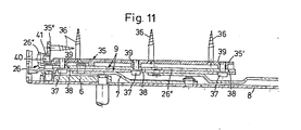
- FIG. 11 shows, in a representation corresponding to FIG. 4, a construction of the opening device which is advantageously further developed.
- the angle piece 26 forming the wing-side holding rail 9 with its longer, horizontal leg 26 is placed on the horizontal leg 35" of a retaining bar 35 which is also designed as an angle piece and is received in the narrow cross-sectional area of the step-like profile groove on the folded peripheral surface of the wing 2.
- the retaining bar 35 is anchored to the wing 2 by fastening screws 36, these fastening screws 36 each engaging in the horizontal leg 35 ′′ and also in the upright leg 35 ′′ of the retaining bar 35.
- the holding rail 9 is in turn via clamping screws 37 with the holding bar 35 in a releasable connection, such that each clamping screw 37 passes through a longitudinal slot 38 in the leg 26 1 of the angle piece 26 and with a thread 39 in the horizontal leg 35 1 of the holding bar 35 in engagement stands.
- a threaded element 40 is used as the adjusting device.
- This threaded element 40 is rotatable, but preferably axially immovable in the upright leg 26 "of the holding rail 9 or the angle piece 26 and on the other hand engages in an internal thread 41 which is located in the upright leg 35" of the holding bar 35.
- the end of the threaded element 40 protruding from the leg 26 '' of the holding rail 9 or the angle piece 26 is provided with an engagement hole (not shown), preferably an internal hexagon, into which a suitably profiled socket wrench can be inserted for the purpose of adjustment.
- an engagement hole (not shown), preferably an internal hexagon, into which a suitably profiled socket wrench can be inserted for the purpose of adjustment.
Abstract
Description
Die Erfindung betrifft eine Ausstellvorrichtung für die Flügel von Fenstern, Türen od. dgl., bestehend aus einer rahmenseitig im Falz zu befestigenden Lagerschiene und einer flügelseitig ebenfalls im Falz angreifenden Halteschiene sowie aus zwei Lenkern von unterschiedlicher Länge, die über je ein Drehgelenk mit der Lagerschiene und der Halteschiene in Verbindung stehen und mit diesen ein Lenkertrapez bilden, dessen kürzestes Glied die flügelseitig angreifende Halteschiene ist.The invention relates to an opening device for the sash of windows, doors or the like, consisting of a mounting rail to be fastened on the frame side in the rebate and a holding rail also engaging in the rebate on the wing side as well as two links of different lengths, each having a swivel joint with the mounting rail and the holding rail are connected and form a trapezoidal handlebar with the shortest link is the holding rail engaging on the wing side.
Eine Ausstellvorrichtung dieser Gattung ist bereits bekannt durch die GB-PS 1 163 798.An opening device of this type is already known from GB-PS 1 163 798.
Bei dieser bekannten Ausstellvorrichtung ist einerseits die Lagerschiene am feststehenden Rahmen und andererseits die Halteschiene am Flügel fest angeschraubt und die beiden Lenker sind sowohl mit der rahmenseitigen Lagerschiene als auch mit der flügelseitigen Halteschiene jeweils unlösbar über die Drehgelenke gekuppelt. Jedes Drehgelenk ist mit einer selbstschmierenden Plastikbuchse ausgestattet, welche vom Drehzapfen durchsetzt ist und einerseits von einem Bund sowie andererseits von einem Nietkragen desselben so verspannt wird, daß ein Reibungskontakt in jedem Drehgelenk entsteht und sämtliche Drehgelenke gemeinsam den Flügel in jeder beliebigen Öffnungsstellung festbremsen.In this known opening device, on the one hand the bearing rail is firmly screwed to the fixed frame and on the other hand the holding rail on the wing and the two links are inextricably coupled to both the frame-side bearing rail and the wing-side holding rail via the swivel joints. Each swivel joint is equipped with a self-lubricating plastic bushing, which is penetrated by the pivot pin and is clamped on the one hand by a collar and on the other hand by a rivet collar so that a frictional contact arises in every swivel joint and all swivel joints brake the sash together in any open position.
Nachteilig bei der bekannten Ausstellvorrichtung ist es, daß der Flügel relativ zum feststehenden Rahmen nur dadurch ausgebaut werden kann, daß entweder die rahmenseitige Lagerschiene oder aber die flügelseitige Halteschiene jeweils durch Entfernen der Befestigungsschrauben gelöst werden muß. Abgesehen davon, daß diese Arbeitsweise umständlich und zeitraubend ist, geht nach mehrmaligem Lösen der Befestigungsschrauben leicht deren fester Sitz in den Eingriffsbohrungen verloren, so daß der ordnungsgemäße Halt der Lagerschiene am feststehenden Rahmen und/ oder der Halteschiene am Flügel beeinträchtigt wird. Die ordnungsgemäße Funktion des Fensters oder der Tür ist dann jedoch nicht mehr gewährleistet.A disadvantage of the known opening device is that the wing can only be removed relative to the fixed frame in that either the frame-side bearing rail or the wing-side holding rail must be released by removing the fastening screws. Apart from the fact that this procedure is cumbersome and time-consuming, after loosening the fastening screws several times, their tight fit in the engagement holes is easily lost, so that the proper hold of the bearing rail on the fixed frame and / or the holding rail on the wing is impaired. However, the proper functioning of the window or door can no longer be guaranteed.
Im übrigen eignet sich die bekannte Ausstellvorrichtung nur für den Einbau bei solchen Fenstern, Türen od. dgl. deren Flügel entweder um zu seinen waagerechten Kanten parallele Drehgelenke oder aber um zu seinen senkrechten Kanten parallele Drehgelenke relativ zum feststehenden Rahmen verlagerbar ist. Sie eignen sich jedoch nicht für die Benutzung bei Fenstern, Türen od. dgl., deren Flügel relativ zum feststehenden Rahmen wahlweise seitwärts um zu einer aufrechten Begrenzungskante parallele Drehachsen in einer Öffnungsstellung geschwenkt und auch um seine untere, waagerechte Begrenzungskante in einer Öffnungsstellung gekippt werden kann.Otherwise, the known opening device is only suitable for installation in such windows, doors or the like. The sash can be displaced relative to the fixed frame either about pivot joints parallel to its horizontal edges or about pivot joints parallel to its vertical edges. However, they are not suitable for use with windows, doors or the like, the wings of which can optionally be pivoted sideways relative to the fixed frame about axes of rotation parallel to an upright boundary edge in an open position and also tilted about its lower, horizontal boundary edge in an open position .
Da aber beim heutigen Stand der Technik Fenster und Türen od. dgl. mit Drehkippflügel weit verbreitet zum Einsatz gelangen, zielt die Neuerung auf die Schaffung einer gattungsgemäßen Ausstellvorrichtung ab, die nicht nur ein leichtes und problemloses Kuppeln und Entkuppeln des Flügels vom feststehenden Rahmen ermöglicht, sondern zugleich auch die Öffnungs- und Schließbewegung des Flügels gegenüber dem feststehenden Rahmen um zwei im rechten Winkel zueinander gerichtete Begrenzungskanten gewährleistet.However, since windows and doors or the like with a tilt-and-turn sash are widely used in the current state of the art, the innovation aims to create a generic display device that not only enables the wing to be easily and easily coupled and uncoupled from the fixed frame, but at the same time also ensures the opening and closing movement of the sash relative to the fixed frame by two boundary edges directed at right angles to one another.
Die Lösung dieser Aufgabe wird nach der Erfindung mit den Kennzeichnungsmerkmalen des Anspruchs 1, nämlich dadurch erreicht, daß zwei der vier Drehgelenke entkuppelbar ausgebildet sind und dabei wenigstens eines dieser entkuppelbaren Drehgelenke aus einem Spurzapfen-Kipplager besteht, bei dem das den Spurzapfen bildende Lagerteil und das diesen Spurzapfen aufnehmende Lagerteil konzentrisch von sphärischen Stützlagerflächen umgeben sind, die ringförmig ineinander greifen und die in Achsrichtung des Spurzapfens gerichteten Lagerkräfte aufnehmen.The solution to this problem is achieved according to the invention with the characterizing features of claim 1, namely in that two of the four rotary joints are designed to be uncoupled and at least one of these uncouplable rotary joints consists of a pivot pin tilting bearing, in which the bearing part forming the pivot pin and the bearing part receiving this tracking pin are concentrically surrounded by spherical support bearing surfaces which engage in a ring and absorb the bearing forces directed in the axial direction of the tracking pin.
Als besonders empfehlenswert hat sich nach der Erfindung eine Ausgestaltung erwiesen, bei der gemäß Anspruch 2 der Spurzapfen an seinem freien Ende zusätzlich eine sphärische Lagerkuppe aufweist, und das ihn aufnehmende Lagerteil mit einer komplemtär sphärischen Lagermulde versehen ist, wobei Lagerkuppe und Lagermulde mit den umgebenden Stützlagerflächen ein gemeinsames Zentrum aufweisen. Es ergibt sich auf diese Art und Weise ein besonders großflächiges und damit tragfähiges Lagersystem.According to the invention, an embodiment has proven to be particularly recommendable, in which, according to
Nach Anspruch 3 zeichnet sich die erfindungsgemäße Ausstellvorrichtung durch Anordnung als unteres Ecklager zwischen dem feststehenden Rahmen und dem Flügel eines Drehkippfensters, einer Drehkipptür od. dgl. aus. In diesem Falle erweist es sich als besonders wichtig, wenn neuerungsgemäß nach Anspruch 4 das rahmenseitige Drehgelenk des langen Lenkers und das flügelseitige Drehgelenk des kurzen Lenkers entkuppelbar ausgebildet sind und dabei mindestens das flügelseitige Drehgelenk des kurzen Lenkers als Spurzapfen-Kipplager ausgeführt ist.According to
Nach der Weiterbildungsmaßnahme der erfindungsgemäßen Ausstellvorrichtung gemäß Anspruch 5 besteht das rahmenseitige Drehgelenk des langen Lenkers aus einem am Gelenkzapfen verrastbaren Sicherungsring und einer zwischen diesem und dem Lenker angeordneten Scheibe, wobei die dem Lenker zugewendete Fläche der Scheibe flach kegelförmig oder sphärisch gewölbt ausgebildet ist.According to the training measure of the display device according to the invention according to
Weiterhin ist nach Anspruch 6 vorgesehen, daß der lange Lenker im Bereich seines rahmenseitigen Drehgelenkes ein gegen die Lagerschiene hin erhaben gewölbtes bzw. dachförmiges Querschnittsprofil aufweist und auf der Lagerschiene relativ zum Drehgelenk um seine Längsachse begrenzt kippbar abgestützt ist. Ferner können gemäß Anspruch 7 der lange Lenker und der kurze Lenker ein Längenverhältnis von etwa 2 : 1 aufweisen, während das Abstandsmaß der beiden rahmenseitigen Drehgelenke zum Abstandsmaß der beiden flügelseitigen Drehgelenke im Verhältnis von etwa 3,4 : 1 steht. Es ergibt sich hierdurch eine besonders günstige Verlagerungsbewegung des Flügels relativ zum feststehenden Rahmen bei seiner Öffnungs- und Schließbewegung um eine seitliche, aufrechte Begrenzungskante.Furthermore, it is provided according to
Bewährt hat sich in erfindungsgemäßer Weiterbildung der Ausstellvorrichtung auch die Ausgestaltung nach Anspruch 8, die darin liegt, daß die flügelseitige Halteschiene aus einem Winkelstück und einer mit dem waagerechten Schenkel derselben durch die beiden Drehgelenke verbundenen Riegelstück besteht und auch die rahmenseitige Lagerschiene als Winkelstück ausgebildet ist, dessen aufrechter Schenkel einen Riegeleingriff für das flügelseitige Riegelstück aufweist bzw. trägt.In a further development of the opening device according to the invention, the embodiment according to
Nach Anspruch 9 kann des weiteren die rahmenseitige Halteschiene wenigstens im Bereich des Drehgelenkes für den kurzen Lenker mit einem Einbohrzapfen für den Eingriff in eine rahmenseitige Bohrung versehen werden, während gemäß Anspruch 10 vorgesehen ist, daß das Winkelstück der flügelseitigen Halteschiene wenigstens an den Enden beider Schenkel einwärts gerichtete Profilvorsprünge trägt, die formschlüssig in eine stufenförmig abgesetzte Profilnut am Flügelfalz eingreifen.According to
Die Maßnahmen des Anspruchs 11 bestehen nach der Erfindung darin, daß das flügelseitige Riegelstück und der rahmenseitige Riegeleingriff sich in Schließlage des Flügels gegenseitig hintergreifende Keilstücke tragen und mit quer zu den Achsen der Drehgelenke gerichteten Stützflächen als Aushebesicherung für den gekippten Flügel versehen sind.The measures of
Schließlich hat es sich zur Erzielung einer kompakten Bauweise der Ausstellvorrichtung auch bewährt, wenn nach Anspruch 12 das Zentrum der sphärischen Lagerflächen innerhalb der Ebene des Lenkers liegt.Finally, in order to achieve a compact design of the opening device, it has also proven useful if the center of the spherical bearing surfaces lies within the plane of the handlebar.
Es hat sich des weiteren als besonders vorteilhaft erwiesen, wenn nach Anspruch 13 die flügelseitige Halteschiene'auf einer Halteleiste begrenzt längsschiebbar geführt ist und an ihrem hinteren Ende über ein Gewindeelement mit der Halteleiste in Stellverbindung steht, wobei die Halteleiste im schmalen Querschnittsteil einer stufenartig abgesetzten Profilnut an der Falzumfangsfläche des Flügel befestigbar ist, während die Halteschiene im breiteren Querschnittsteil dieser Profilnut liegt.It has furthermore proven to be particularly advantageous if, according to
Durch diese Maßnahme kann bei in Drehstellung geöffnetem Flügel über das Gewindeelement innerhalb gewisser Grenzen eine Verlagerung des Flügels gegenüber dem feststehenden Rahmen in Richtung parallel zu seiner Ebene vorgenommen werden.By means of this measure, with the sash open in the rotational position, the sash can be displaced within certain limits relative to the fixed frame in the direction parallel to its plane.
Nach Anspruch 14 wird sowohl die Halteschiene als auch die Halteleiste von einem Winkelstück gebildet, wobei das Gewindeelement jeweils in den aufrechten Schenkeln derselben sitzt und/oder sein Widerlager hat.According to
Vorteilhaft ist es auch, wenn die Halteleiste über mehrere Befestigungsschrauben am Flügel verankerbar ist, während die Halteschiene mit der Halteleiste über Längsschlitze durchsetzte Klemmschrauben lösbar gekuppelt ist.It is also advantageous if the retaining bar can be anchored to the wing by means of a plurality of fastening screws, while the retaining rail is detachably coupled to the retaining bar by means of clamping screws passed through longitudinal slots.
Durch die FR-PS 22 33 867 ist zwar auch bereits eine gattungsähnliche Ausstellvorrichtung bekannt geworden, die sich für die Benutzung in Verbindung mit Drehkippfenstern und -türen od. dgl. eignet. Dort ist jedoch die flügelseitige Halteschiene mit der rahmenseitigen Lagerschiene nur unter Zwischenschaltung eines einzigen Lenkers verbunden, wobei das hintere Ende der Halteschiene über einen Drehzapfen verschiebbar unmittelbar mit der rahmenseitigen Lagerschiene in Eingriff steht.FR-
Der wesentliche Nachteil dieser bekannten Ausstellvorrichtung liegt jedoch darin, daß sie nur bei Fenstern, Türen od. dgl. in Benutzung genommen werden kann, deren Flügel in seiner Schließlage relativ zum feststehenden Rahmen raumseitig flächenbündig eingebaut ist, bei denen also der Flügel keinen sogenannten Überschlag aufweist. Der Flügel läßt sich nämlich nur dann in Drehstellung öffnen, wenn seine den Ausstellvorrichtungen benachbarten Bereiche in den Lichtraum zwischen den Schenkeln des feststehenden Rahmens einschwenken können.The main disadvantage of this known opening device is, however, that it can only be used with windows, doors or the like, the sash of which is installed flush with the room in its closed position relative to the fixed frame, in which case the sash does not have a so-called rollover . The sash can only be opened in the rotational position if its areas adjacent to the opening devices can pivot into the light space between the legs of the fixed frame.
Weitere Merkmale und Vorteile des Gegenstandes der Erfindung werden nachfolgend an einem in der Zeichnung dargestellten Ausführungsbeispiel erläutert. Es zeigt
- Fig. 1 in schematisch vereinfachter Draufsichtdarstellung ein Fenster mit in seiner Schließlage am feststehenden Rahmen anliegendem Flügel,
- Fig. 2 wiederum in schematisch vereinfachter Darstellung und Draufsicht das Fenster mit gegenüber dem feststehenden Rahmen in Drehstellung geöffnetem Flügel,
- Fig. 3 gleichfalls in schematisch vereinfachter Draufsichtdarstellung das Fenster mit gegenüber dem feststehenden Rahmen in Kippstellung geöffnetem Flügel,
- Fig. 4 in Ansicht von vorne sowie im Vertikalschnitt eine als Drehkipp-Ecklager ausgebildete Ausstellvorrichtung bei in Schließlage am feststehenden Rahmen befindlichem Flügel,
- Fig. 5 einen Schnitt entlang der Linie V - V in Fig. 4,
- Fig. 6 einen Schnitt gemäß Fig. 5 bei in Kipprichtung geöffnetem Flügel,
- Fig. 7 einen Schnitt entlang der Linie VII - VII in Fig. 4,
- Fig. 8 den der Fig. 7 entsprechenden Schnitt, jedoch bei in Kippstellung geöffnetem Flügel,
- Fig. 9 eine Ansicht der Ausstellvorrichtung in Pfeilrichtung IX der Fig. 4 bei in Drehstellung gegenüber dem festststehenden Rahmen geöffnetem Flügel,
- Fig. 10 in vergrößertem Maßstab den in Fig. 5 mit X gekennzeichneten Bereich, und
- Fig. 11 eine der Fig. 4 entsprechende Darstellung einer abgewandelten Bauart der Ausstellvorrichtung zeigt.
- 1 in a schematically simplified plan view, a window with the wing resting in its closed position on the fixed frame,
- 2 again in a schematically simplified representation and top view of the window with the sash open relative to the fixed frame in the rotational position,
- 3 likewise in a schematically simplified plan view representation the window with the sash open in relation to the fixed frame in the tilted position,
- 4 is a view from the front and in vertical section of an opening device designed as a tilt and turn corner bearing with the wing located in the closed position on the fixed frame,
- 5 shows a section along the line V - V in FIG. 4,
- 6 shows a section according to FIG. 5 with the wing open in the tilting direction,
- 7 shows a section along the line VII - VII in FIG. 4,
- 8 shows the section corresponding to FIG. 7, but with the wing open in the tilted position,
- 9 is a view of the opening device in the direction of arrow IX of FIG. 4 with the sash open in the rotational position relative to the fixed frame,
- Fig. 10 on an enlarged scale the area marked X in Fig. 5, and
- FIG. 11 shows a representation corresponding to FIG. 4 of a modified design of the opening device.
In Fig. 1 der Zeichnung ist schematisch ein Drehkippfenster angedeutet, bei dem am feststehenden Rahmen 1 der Flügel 2 in seiner Schließlage anliegt. Fig. 2 der Zeichnung zeigt das gleiche Drehkippfenster, wobei jedoch der Flügel 2 relativ zum feststehenden Rahmen 1 um parallel zu einer aufrechten Seitenkante gerichtete Gelenke 3', 3"und 4', 4" in Drehöffnungsstellung gebracht ist. Schließlich zeigt die Fig. 3 der Zeichnung das Drehkippfenster, wobei der Flügel 2 relativ zum feststehenden Rahmen 1 seine Kippöffnungsstellung einnimmt und seine Kippöffnungsweite durch eine zwischen den oberen, waagerechten Holmen von feststehendem Rahmen 1 und Flügel 2 eingebaute Ausstellvorrichtung 5 begrenzt ist. Auch die Ausstellvorrichtung 5 wirkt dabei über Gelenke 3', 3'' und 4' , 4"mit dem feststehenden Rahmen 1 zusammen.In Fig. 1 of the drawing, a tilt and turn window is indicated schematically, in which the fixed frame 1 of the
Die Gelenke 3', 3'' und 4', 4'' sind in ein und derselben Anordnung und Ausbildung sowohl im Bereich der oberen waagerechten Fälze als auch im Bereich der unteren waagerechten Fälze zwischen dem feststehenden Rahmen 1 und dem Flügel 2 vorgesehen. Die Achsen dieser Gelenke 3', 3" und 4', 4'' verlaufen dabei jeweils parallel zu den aufrechte Begrenzungskanten von feststehendem Rahmen 1 und Flügel 2.The joints 3 ', 3' 'and 4', 4 '' are provided in one and the same arrangement and design both in the area of the upper horizontal folds and in the area of the lower horizontal folds between the fixed frame 1 and the
Die Gelenke 3'und 3"befinden sich dabei jeweils an den Enden eines kurzen Lenkers 6, während die Gelenke 4'und 4"an den Enden eines langen Lenkers 7 vorgesehen sind. Über das Gelenk 3'steht dabei der Lenker 6 mit dem feststehenden Rahmen 1 in Verbindung, während er über das Gelenk 3"am Flügel 2 angreift. Der Lenker 7 ist wiederum über das Gelenk 4' am feststehenden Rahmen 1 angelenkt, während er über sein Gelenk 4'' am Flügel 2 angreift. Die beiden Gelenke 3' und 4' sindThe
mit einer am feststehenden Rahmen 1 durch Schrauben zu befestigenden Lagerschiene 8 verbunden, die parallel zur Ebene des feststehenden Rahmens 1 gerichtet an dessen Falzumfangsfläche befestigt ist. Die Gelenke 3"und 4'' greifen hingegen an einer Halteschiene 9 an, die am Flügel 2, ebenfalls parallel zu dessen Ebene gerichtet mit der Falzumfangsfläche verbunden wird. Das Gelenk 3' zwischen dem Lenker 6 und dem feststehenden Rahmen 1 und das Gelenk 4'' zwischen dem Lenker 7 und dem Flügel 2 sind jeweils als reine Drehgelenke ausgeführt, wie das der Fig. 4 entnommen werden kann. Das Gelenk 3"zwischen dem Lenker 6 und dem Flügel 2 ist als Spurzapfen-Kipplager 10/11 ausgeführt, das einen Spurzapfen- Lagerteil 10 und ein Spurzapfen-Aufnahmeteil 11 umfaßt. Das Gelenk 4'zwischen dem Lenker 7 und der rahmenseitigen Lagerschiene 8 ist als Drehgelenk ausgelegt, auf dem der Lenker 7 über einen geringfügigen Winkelbereich parallel zu seiner Längsmittelebene kippbar gehalten wird.connected to a fixed to the fixed frame 1 by
Das als Spurzapfen-Kipplager 10/11 ausgelegte Gelenk 3"weist an seinem Spurzapfen-Lagerteil 10 nicht nur den Spurzapfen 12 mit einer sphärischen Lagerkuppe 13 auf, der in eine Spurbohrung 14 mit sphärischer Lagermulde 15 des aufnehmenden Lagerteils 11 eingreift. Vielmehr ist das den Spurzapfen 12 aufnehmende Lagerteil 11 noch konzentrisch von sphärischen Stützlagerflächen 16 umgeben, die kugelschichtförmig ausgeformt sind und mit komplementären sphärischen Stützlagerflächen 17 zusammenwirken kann, die sich am Spurzapfen-Lagerteil 10 befinden, wie das deutlich der Fig. 10 entnommen werden kann. Die sphärischen Stützlagerflächen 16 und 17 greifen dabei ringförmig ineinander und haben mit der Lagerkuppe 13 und der Lagermulde 15 ein gemeinsames Zentrum 18, wie das ebenfalls in Fig. 10 angedeutet ist.The joint 3 ″ designed as a pivot
Die ringförmig ineinandergreifenden Stützlagerflächen 17 und 16 von Spurzapfen-Lagerteil 10 und aufnehmendem Lagerteil 11 sind dabei geeignet, die in Achsrichtung des Spurzapfens 12 gerichteten Lagerkräfte großflächig aufzunehmen.The ring-shaped interlocking
Es ist den Fig. 4 bis 6 und 10 ohne weiteres zu entnehmen, daß das Spurzapfen-Lagerteil 10 und das dieses aufnehmende Lagerteil 11 des Spurzapfen-Kipplagers 10/11 lösbar ineinandergreifen, derart, daß sich die flügelseitige Halteschiene 9 im Bedarfsfalle vom kurzen Lenker 6 lösen bzw. entkuppeln läßt, um ein Aushängen des Flügels2 zu ermöglichen. Auch das Gelenk 4' zwischen dem langen Lenker 7 und der rahmenseitigen Lagerschiene 8 ist entkuppelbar ausgeführt. Es weist zu diesem Zweck einen mit der rahmenseitigen Lagerschiene 8 fest vernieteten Gelenkzapfen 19 auf, der nahe seinem freien Ende mit einer Umfangsnut 20 versehen ist, in der sich ein federnder Sicherungsring 21 verrasten läßt. Zwischen dem Sicherungsring 21 und dem auf den Gelenkzapfen 19 aufgesteckten Lagerende des Lenkers 7 ist darüberhinaus noch eine Scheibe 22 vorgesehen, deren dem Lenker 7 zugewendete Fläche 23 flach kegelförmig oder sphärisch gewölbt ausgebildet ist.4 to 6 and 10 that the track
Da der lange Lenker 7 im Bereich des rahmenseitigen Gelenkes 4'ein gegen die Lagerschiene 8 hin erhaben gewölbtes bzw. dachförmiges Querschnittsprofil aufweist, wie das die Fig. 7 und 8 erkennen lassen, kann er zwischen der Fläche 23 der Scheibe 22 und der Lagerschiene 8 relativ zum Gelenkbolzen 19 um seine Längsmittelebene begrenzt kippen, wie das die Fig. 7 und 8 erkennen lassen, während er sich auf der Lagerschiene 8 abstützt. Durch Entfernen des Sicherungsringes 21 und der Scheibe 22 kann der lange Lenker 7 im Bedarfsfalle leicht vom Gelenkzapfen 19 des mit der Lagerschiene 8 gebildeten Gelenkes 4' entkuppelt werden.Since the
Die in den Fig. 4 bis 9 der Zeichnung dargestellte Ausgestaltung einer Ausstellvorrichtung für Drehkippflügel ist als unteres Ecklager zwischen dem feststehenden Rahmen 1 und dem Flügel 2 des Drehkippfensters bzw. der Drehkipptür ausgelegt. Sie kann jedoch in ähnlicher Weise auch für das Zusammenwirken mit der Drehkipp-Austellvorrichtung 5 nach Fig. 3 ausgelegt werden. In diesem Falle wird dann die flügelseitige Halteschiene 9 nicht direkt an der oberen waagerechten Falzumfangsfläche des Flügels 2 befestigt, sondern sie bildet vielmehr das hintere Ende des wahlweise mit dem Flügel 2 kuppelbaren bzw. davon abkuppelbaren Ausstellarmes 5'der Ausstellvorrichtung 5, wie er in Fig. 3 zu sehen ist.The embodiment of an opening device for tilt and turn sash shown in FIGS. 4 to 9 of the drawing is designed as a lower corner bearing between the fixed frame 1 and the
Es hat sich bewährt, wenn der lange Lenker 7 und der kurze Lenker 6 relativ zueinander ein Längenverhältnis von etwa 2 : 1 aufweisen, während das Abstandsmaß 24 zwischen den beiden rahmenseitigen Gelenken 3'und 4' zum Abstandsmaß 25 zwischen den beiden flügelseitigen Gelenken 3" und 4" im Verhältnis von etwa 3,4 : 1 steht. Es hat sich nämlich gezeigt, daß auf diese Art und Weise unter Einhaltung relativ kleiner Abmessungen eine Ausstellvorrichtung hoher Tragkraft erstellt werden kann, die sich problemlos in dem Luftspalt zwischen der Falzumfangsfläche des feststehenden Rahmens 1 und der dazu parallelen Falzumfangsfläche des Flügels 2 völlig verdeckt unterbringen läßt.It has proven useful if the
Die flügelseitige Halteschiene 9 der Ausstellvorrichtung besteht aus einem Winkelstück 26 mit einem waagerechten Schenkel 26'und einem aufrechten Schenkel 26" und einem mit dem waagerechten Schenkel 26' desselben fest verbundenen Riegelstück 27. Zur Verbindung des Riegelstücks 27 mit dem Schenkel 26' des Winkelstücks 26 dienen dabei Nietzapfen, welche zugleich die Befestigungselemente für die flügelseitigen Teile der Gelenke 3'' und 4" sind.The wing-
Auch die rahmenseitige Lagerschiene 8 ist als Winkelstück 28 ausgebildet, die einen waagerechten Schenkel 28' und einen aufrechten Schenkel 28" aufweist. Der aufrechte Schenkel 28"trägt dabei einen Riegeleingriff 29, mit welchem das Riegelstück 27 über einen Riegelansatz 27 zusammenwirkt, der seitwärts über den aufrechten Schenkel 26"des Winkelstücks 26 hinausragt.The frame-
Aus Fig. 4 ist des weiteren ersichtlich, daß die rahmenseitige Halteschlene 8 wenigstens im Bereich des Drehgelenkes 3' für den kurzen Lenker 6 mit einem Einbohrzapfen 30 versehen ist, der in eine am feststehenden Rahmen 1 parallel zu dessen Ebene vorgesehene Bohrung eingreift und dadurch eine gute Krafteinleitung der Ausstellvorrichtung in den feststehenden Rahmen 1 gewährleistet.From Fig. 4 it can also be seen that the frame-
Das die flügelseitige Halteschiene 9 bildete Winkelstück 26 ist wenigstens an den Enden beider Schenkel 26'und 26'' mit einwärts gerichteten Profilvorsprüngen 31'und 31" versehen, die formschlüssig in eine stufenartig abgesetzte Profilnut an der Falzumfangsfläche des Flügels 2 eingreifen können und dadurch eine gute Halte- und Kraftübertragungsverbindung gewährleisten.The
Der Riegelansatz 27' des flügelseitigen Riegelstücks 27 ist an seinem Ende einerseits mit einer Keilfläche 33' und andererseits mit einer Nase 33" versehen, wie das aus Fig. 9 ersichtlich ist. Der rahmenseitige Riegeleingriff 29 weist ebenfalls eine Keilfläche 32'und eine diesem vorgelagerte Eingriffsnut 32" auf. In der Schließlage des Flügels 2 und beim unteren Ecklager auch in der Kippöffnungsstellung desselben hintergreift die Keilfläche 33' des flügelseitigen Riegelstücks 27 die Keilfläche 32' am rahmenseitigen Riegeleingriff 29, während zugleich die Nase 33" mit der Nut 32" in Eingriff kommt. Während die Keilflächen 31' und 32" in Schließlage und im Bereich des Drehkipp-Ecklagers auch in Kipplage eine Lagensicherung zwischen dem feststehenden Rahmen 1 und dem Flügel 2 gewährleisten, wird durch das Zusammenwirken der Nase 31" mit der Nut 32'' beim Drehöffnen des Flügels 2 sichergestellt, daß dieser über die Lenker 6 und 7 ordnungsgemäß vom feststehenden Rahmen 1 abschwenkt. Außerdem wirkt die Nase 33"bei gekipptem Flügel 2 noch mit einer Anschlagfläche 34 am Riegeleingriff 29 als Aushebesicherung zusammen.The locking projection 27 'of the wing-
Der Fig. 10 kann noch entnommen werden, daß das gemeinsame Zentrum 18 der sphärischen Lagerflächen 13, 15 und 16, 17 des Spurzapfen-Kipplagers 10/11 innerhalb der Dickenabmessung des kurzen Lenkers 6 liegt, so daß sich trotz genügend tiefem Eingriff des Spurzapfens 12 eine relativ geringe Bauhöhe der gesamten Ausstellvorrichtung verwirklichen läßt.10 can also be seen that the
Abschließend sei noch erwähnt, daß zwei zueinander spiegelbildlich gestaltete Ausstellvorrichtungen der aus den Fig. 4 bis 9 ersichtlichen Bauart auch benutzbar sind, um Fenster oder Türen mit Dreh-, Kipp-oder Klappflügeln auszurüsten.Finally, it should also be mentioned that two opening devices of the construction shown in FIGS. 4 to 9 can be used in mirror-image fashion to equip windows or doors with rotating, tilting or folding sashes.
Fig. 11 zeigt in einer der Fig. 4 entsprechenden Darstellung eine in vorteilhafter Weise weitergebildete Bauart der Ausstellvorrichtung. Dort ist das die flügelseitige Halteschiene 9 bildende Winkelstück 26 mit seinem längeren, horizontalen Schenkel 26" auf den waagerechten Schenkel 35" einer ebenfalls als Winkelstück gestalteten Halteleiste 35 gesetzt, die im schmalen Querschnittsbereich der stufenartig abgesetzten Profilnut an der Falzumfangsfläche des Flügels 2 aufgenommen ist.FIG. 11 shows, in a representation corresponding to FIG. 4, a construction of the opening device which is advantageously further developed. There the
Die Halteleiste 35 ist dabei durch Befestigungsschrauben 36 am Flügel 2 verankert, wobei diese Befestigungsschrauben 36 jeweils im waagerechten Schenkel 35" und auch im aufrechten Schenkel 35'' der Halteleiste 35 angreifen.The retaining
Die Halteschiene 9 steht wiederum über Klemmschrauben 37 mit der Halteleiste 35 in lösbarer Verbindung, und zwar dergestalt, daß jede Klemmschraube 37 einen Längsschlitz 38 im Schenkel 261 des Winkelstücks 26 durchsetzt und mit einem Gewinde 39 im waagerechten Schenkel 351 der Halteleiste 35 in Eingriff steht.The holding
Bei gelockerten Klemmschrauben 37 besteht somit die Möglichkeit einer Längsverschiebung der Halteschiene 9 realtiv zur Halteleiste 35, und zwar in einem durch die Längsschlitze 38 begrenzten Ausmaß, das mehrere Millimeter, beispielsweise 2 bis 3 mm, betragen kann.When the clamping screws 37 are loosened, there is thus the possibility of a longitudinal displacement of the holding
Damit bei gelockerten Klemmschrauben 37 die Relativverschiebung zwischen der Halteschiene 9 und der Halteleiste 35 praktisch stufenlos und feinfühlig vorgenommen werden kann, wird ein Gewindeelement 40 als Stellvorrichtung benutzt.In order that the relative displacement between the holding
Dieses Gewindeelement 40 ist dabei drehbar, jedoch vorzugsweise axial unverschiebbar im aufrechten Schenkel 26" der Halteschiene 9 bzw. des Winkelstückes 26 gelagert und greift andererseits in ein Innengewinde 41 ein, das sich im aufrechten Schenkel 35'' der Halteleiste 35 befindet.This threaded
Das aus dem Schenkel 26'' der Halteschiene 9 bzw. des Winkelstücks 26 herausragende Ende des Gewindeelementes 40 ist mit einem - nicht gezeigten - Eingriffsloch, vorzugsweise einem Innensechskant, versehen, in das sich zum Zwecke der Verstellung ein entsprechend profilierter Steckschlüssel einführen läßt. Durch Drehung des Steckschlüssels kann damit die relative Längsverstellung zwischen der Halteschiene 9 und der Halteleiste 35 bewirkt werden. Nach Vornahme der jeweiligen Verstellung werden dann die Klemmschrauben 37 wieder angezogen, so daß zusätzlich eine kraftschlüssige Klemmverbindung zwischen der Halteschiene 9 und der Halteleiste 35 hergestellt ist.The end of the threaded
Claims (15)
dadurch gekennzeichnet,
daß zwei (3"und 4') der vier Drehgelenke (3', 3"und 4', 4") entkuppelbar ausgebildet sind (10, 11 bzw. 20,21) und dabei wenigstens eines (3") der entkuppelbaren Drehgelenke (3", 4') aus einem Spurzapfen-Kipplager (10, 11) besteht, bei dem das den Spurzapfen (12) bildende Lagerteil (10) und das diesen Spurzapfen (12) aufnehmende Lagerteil (11, 14) konzentrisch von sphärischen Stützlagerflächen (17, 16; Fig. 10) umgeben sind, die ringförmig ineinandergreifen und die in Achsrichtung des Spurzapfens (12) gerichteten Lagerkräfte aufnehmen.1.Expansion device for the sash of windows, doors or the like, consisting of a mounting rail to be fastened on the frame side in the rebate and a holding rail also engaging in the rebate side as well as two links of different lengths, each of which has a swivel joint with the bearing rail and the Connect the support rail and form a trapezoidal handlebar with the shortest link is the fold-side support rail,
characterized,
that two (3 "and 4 ') of the four rotary joints (3', 3" and 4 ', 4 ") are designed to be uncouplable (10, 11 and 20, 21) and at least one (3") of the decouplable rotary joints ( 3 ", 4 ') consists of a pivot pin tilting bearing (10, 11), in which the bearing part (10) forming the pivot pin (12) and the bearing part (11, 14) receiving this pivot pin (12) concentrically from spherical support bearing surfaces ( 17, 16; Fig. 10) are surrounded, which engage in a ring and absorb the bearing forces directed in the axial direction of the track pin (12).
dadurch gekennzeichnet,
daß der Spurzapfen (12) an seinem freien Ende zusätzlich eine sphärische Lagerkuppe (13) aufweist und das ihn aufnehmende Lagerteil (11, 14) mit einer komplementär sphärischen Lagermulde (15) versehen ist, wobei Lagerkuppe (13) und Lagermulde (15) mit den umgebenden Stützlagerflächen (17,16) ein gemeinsames Zentrum (18) aufweisen (Fig. 10).2. Display device according to claim 1,
characterized,
that the track pin (12) additionally has a spherical bearing cap (13) at its free end and the bearing part (11, 14) receiving it is provided with a complementary spherical bearing trough (15), the bearing crest (13) and bearing trough (15) with the surrounding support bearing surfaces (17, 16) having a common center (18) (FIG. 10).
gekennzeichnet durch
Anordnung als unteres Ecklager zwischen dem feststehenden Rahmen (1) und dem Flügel (2) eines Drehkippfensters, einer Drehkipptür od. dgl..3. Display device according to one of claims 1 and 2,
marked by
Arrangement as a lower corner bearing between the fixed frame (1) and the wing (2) of a tilt and turn window, a tilt and turn door or the like.
dadurch gekennzeichnet,
daß das rahmenseitige Drehgelenk (4') des langen Lenkers (7) und das flügelseitige Drehgelenk (3") des kurzen Lenkers (6) entkuppelbar ausgebildet sind (20, 21; 10,11) und dabei mindestens das flügelseitige Drehgelenk (3") des kurzen Lenkers (6) als Spurzapfen-Kipplager (10, 11) ausgeführt ist.4. Display device according to one of claims 1 to 3,
characterized,
that the frame-side swivel joint (4 ') of the long link (7) and the wing-side swivel joint (3 ") of the short link (6) are designed to be uncouplable (20, 21; 10, 11) and at least the wing-side swivel joint (3") the short handlebar (6) is designed as a pivot pin tilt bearing (10, 11).
dadurch gekennzeichnet,
daß das rahmenseitige Drehgelenk (4') des langen Lenkers (7) aus einem am Gelenkzapfen (19) verrastbaren (20) Sicherungsring (21) und einer zwischen diesem und dem Lenker (7) angeordneten Scheibe (22) besteht, wobei die dem Lenker (7) zugewendete Fläche (23) der Scheibe (22) flach kegelförmig oder sphärisch gewölbt ausgebildet ist.5. Display device according to one of claims 1 to 4,
characterized,
that the frame-side pivot joint (4 ') of the long handlebar (7) consists of a lockable on the pivot pin (19) (20) locking ring (21) and a disc (22) arranged between the latter and the handlebar (7), the handlebar (7) facing surface (23) of the disc (22) is flat, conical or spherically curved.
dadurch gekennzeichnet,
daß der lange Lenker (7) im Bereich seines rahmenseitigen Drehgelenks (4') ein gegen die Lagerschiene (8) erhaben gewölbtes bzw. dachförmiges Querschnittsprofil aufweist (Fig. 7 und 8) und auf der Lagerschiene (8) relativ zum Drehgelenk (4') um seine Längsachse begrenzt kippbar abgestützt ist.6. Display device according to one of claims 1 to 5,
characterized,
that the long link (7) in the area of its frame-side swivel joint (4 ') has a raised or roof-shaped cross-sectional profile against the bearing rail (8) (FIGS. 7 and 8) and on the bearing rail (8) is supported such that it can be tilted to a limited extent about its longitudinal axis relative to the swivel joint (4 ').
dadurch gekennzeichnet,
daß der lange Lenker (7) und der kurze Lenker (6) ein Längenverhältnis von etwa 2 : 1 aufweisen, während das Abstandsmaß (24) der beiden rahmenseitigen Drehglenke (3'und 4') zum Abstandsmaß (25) der beiden flügelseitigen Drehgelenke (3'' und 4'') im Verhältnis von etwa 3,4 : 1 steht.7. Display device according to one of claims 1 to 6,
characterized,
that the long link (7) and the short link (6) have an aspect ratio of about 2: 1, while the distance dimension (24) of the two frame-side pivot joints (3 'and 4') to the distance dimension (25) of the two wing-side pivot joints ( 3 "and 4") is in the ratio of about 3.4: 1.
dadurch gekennzeichnet,
daß die flügelseitige Halteschiene (9) aus einem Winkelstück (26) und einer mit dem waagerechten Schenkel (26') deselben durch die beiden Drehgelenke (3'' und 4'') verbundenen Riegelstück (27) besteht und auch die rahmenseitige Lagerschiene (8) als Winkelstück (28) ausgebildet ist, dessen aufrechter Schenkel (28") einen Riegeleingriff (29) für das flügelseitige Riegelstück (27) aufweist bzw. trägt.8. Display device according to one of claims 1 to 7,
characterized,
that the wing-side holding rail (9) consists of an angle piece (26) and a locking piece (27) connected to the horizontal leg (26 ') of the same by the two swivel joints (3''and4'') and also the frame-side bearing rail (8 ) is designed as an angle piece (28), the upright leg (28 ") of which has or carries a locking engagement (29) for the wing-side locking piece (27).
daß die rahmenseitige Lagerschiene (8) wenigstens im Bereich des Drehgelenkes (3') für den kurzen Lenker (6) mit einem damit fluchtenden Einbohrzapfen (30) für den Eingriff in eine rahmenseitige Bohrung versehen ist.9. Display device according to one of claims 1 to 8, characterized in
that the frame-side bearing rail (8) is provided at least in the region of the swivel joint (3 ') for the short handlebar (6) with an aligned drilling pin (30) for engaging in a frame-side bore.
dadurch gekennzeichnet,
daß das Winkelstück (26) der flügelseitigen Halteschiene (9) wenigstens an den Enden beider Schenkel (26' und 26") einwärts gerichtete Profilvorsprünge (31', 31") trägt, die formschlüssig in eine stufenförmig abgesetzte Profilnut an der Flügelfalzumfangsfläche eingreifen.10. Display device according to one of claims 1 to 9,
characterized,
that the angle piece (26) of the wing-side holding rail (9) at least at the ends of both legs (26 'and 26 ") carries inwardly directed profile projections (31', 31") which engage positively in a stepped profile groove on the sash rebate circumferential surface.
dadurch gekennzeichnet,
daß das flügelseitige Riegelstück (27) und der rahmenseitige Riegeleingriff (29) sich in Schließlage des Flügels (2) gegenseitig hintergreifende Keilstücke (33', 32'), tragen und mit quer zu den Achsen der Drehgelenke gerichteten Stützflächen (34) als Aushebesicherung für den gekippten Flügel (2) versehen sind.11. Display device according to one of claims 1 to 10,
characterized,
that the wing-side locking piece (27) and the frame-side locking engagement (29) in the closed position of the wing (2) mutually engaging wedge pieces (33 ', 32'), and with transverse to the axes of the rotary joints supporting surfaces (34) as a lifeline for the tilted wing (2) are provided.
dadurch gekennzeichnet,
daß das Zentrum (18) der sphärischen Lagerflächen (13, 15 und 16, 17) innerhalb der Ebene des Lenkers (6) liegt (Fig. 4 bis 6 und 10).12. Display device according to one of claims 1 to 11,
characterized,
that the center (18) of the spherical bearing surfaces (13, 15 and 16, 17) lies within the plane of the handlebar (6) (FIGS. 4 to 6 and 10).
dadurch gekennzeichnet,
daß die flügelseitige Halteschiene (9) auf einer Halteleiste (35) begrenzt längsschiebbar geführt (37, 38) und an ihrem hinteren Ende über ein Gewindeelement (40) mit der Halteleiste (35) in Stellverbindung (41) steht, wobei die Halteleiste (35) im schmalen Querschnittsteil einer stufenartig abgesetzten Profilnut an der Falzumfangsfläche des Flügels (2) befestigt ist, während die Halteschiene (9) im breiteren Querschnittsteil dieser Profilnut liegt.13. Display device according to one of claims 1 to 12,
characterized,
that the wing-side retaining rail (9) on a retaining strip (35) is guided in a longitudinally displaceable manner (37, 38) and at its rear end via a threaded element (40) is in adjusting connection (41) with the retaining strip (35), the retaining strip (35 ) is fastened in the narrow cross-sectional part of a stepped profile groove to the rebate peripheral surface of the wing (2), while the holding rail (9) lies in the wider cross-sectional part of this profile groove.
dadurch gekennzeichnet,
daß sowohl die Halteschiene (9) als auch die Halteleiste (35) von einem Winkelstück (26, 26", 26'' bzw. 35, 35', 35'') gebildet ist und das Gewindeelement (40) jeweils in den aufrechten Schenkeln (26'' und 35'') derselben sitzt und/oder sein Widerlager hat.14. Display device according to claim 13,
characterized,
that both the holding rail (9) and the holding strip (35) are formed by an angle piece (26, 26 ", 26" or 35, 35 ', 35 ") and the threaded element (40) in each case in the upright legs (26 '' and 35 '') of the same sits and / or has its abutment.
dadurch gekennzeichnet,
daß die Halteleiste (35) über mehrere Befestigungsschrauben (36) am Flügel (2) verankerbar ist, während die Halteschiene (9) mit der Halteleiste (35) über Längsschlitze (38) durchsetzende Klemmschrauben (37) lösbar gekuppelt ist.15. Display device according to one of claims 13 and 14,
characterized,
that the retaining strip (35) can be anchored to the wing (2) by means of a plurality of fastening screws (36), while the retaining rail (9) is detachably coupled to the retaining strip (35) via longitudinal slots (38) by means of clamping screws (37).
Priority Applications (1)
| Application Number | Priority Date | Filing Date | Title |
|---|---|---|---|
| AT86107320T ATE36369T1 (en) | 1985-06-07 | 1986-05-30 | EXPOSURE DEVICE FOR THE SASHES OF WINDOWS, DOORS OR. DGL. |
Applications Claiming Priority (2)
| Application Number | Priority Date | Filing Date | Title |
|---|---|---|---|
| DE8516560U DE8516560U1 (en) | 1985-06-07 | 1985-06-07 | Opening device for the sash of windows, doors or the like. |
| DE8516560U | 1985-06-07 |
Publications (3)
| Publication Number | Publication Date |
|---|---|
| EP0204267A2 true EP0204267A2 (en) | 1986-12-10 |
| EP0204267A3 EP0204267A3 (en) | 1987-05-13 |
| EP0204267B1 EP0204267B1 (en) | 1988-08-10 |
Family
ID=6781854
Family Applications (1)
| Application Number | Title | Priority Date | Filing Date |
|---|---|---|---|
| EP86107320A Expired EP0204267B1 (en) | 1985-06-07 | 1986-05-30 | Fitting arrangement for tiltable wings of windows, doors or the like |
Country Status (7)
| Country | Link |
|---|---|
| EP (1) | EP0204267B1 (en) |
| AT (1) | ATE36369T1 (en) |
| DE (2) | DE8516560U1 (en) |
| DK (1) | DK161464C (en) |
| ES (1) | ES294621Y (en) |
| FI (1) | FI81170C (en) |
| NO (1) | NO161134C (en) |
Cited By (17)
| Publication number | Priority date | Publication date | Assignee | Title |
|---|---|---|---|---|
| FR2632679A1 (en) * | 1988-06-13 | 1989-12-15 | Ferco Int Usine Ferrures | JOINT FITTINGS FOR DOOR, WINDOW OR THE LIKE, OSCILLO-BRIDING |
| DE3829053A1 (en) * | 1988-08-26 | 1990-03-08 | Winkhaus Fa August | TURN-FITTING OR TURN-TIP FITTING OF WINDOWS, DOORS OR THE LIKE |
| DE3834388C1 (en) * | 1988-10-10 | 1990-03-22 | Siegenia-Frank Kg, 5900 Siegen, De | |
| US4986028A (en) * | 1989-06-19 | 1991-01-22 | Siegenia-Frank Kg | Mounting bracket |
| DE9301655U1 (en) * | 1993-02-06 | 1994-06-09 | Siegenia Frank Kg | Hinge fitting |
| EP0616106A1 (en) * | 1993-03-15 | 1994-09-21 | Siegenia-Frank Kg | Window or door with hinge fitting |
| EP0628693A2 (en) * | 1993-06-10 | 1994-12-14 | Gretsch-Unitas GmbH Baubeschläge | Corner support, in particular for an at least pivotal bearing of a wing, a window, a door or similar |
| AT401669B (en) * | 1986-01-17 | 1996-11-25 | Hautau Gmbh W | HIDDEN FITTING FOR SWINGARM BEARINGS, ESPECIALLY FOR TILTING SWIVEL BEARING WINGS OF WINDOWS AND DOORS |
| GB2325961A (en) * | 1997-06-06 | 1998-12-09 | Euromond Ltd | Friction stay |
| EP1426534A1 (en) * | 2002-11-18 | 2004-06-09 | W. HAUTAU GmbH | Fitting for the metal frame of turn - tilt window or door panels |
| EP1788178A1 (en) * | 2005-11-22 | 2007-05-23 | Roto Frank Ag | Bearing for windows, doors or the like |
| EP1788175A1 (en) * | 2005-11-22 | 2007-05-23 | Roto Frank Ag | Flat links assembly for windows, doors or the like |
| DE102007054477A1 (en) * | 2007-11-13 | 2009-06-04 | Roto Frank Ag | Corner bearing arrangement for e.g. rotatable and/or tiltable wing, of e.g. door, has control plate carrying suspension bolt for rotatably and tiltably mounting wing in plate, and corner hinge firmly attached to wing |
| EP2292882A1 (en) * | 2002-11-18 | 2011-03-09 | HAUTAU GmbH | Fitting for the metal frame of turn-tilt window or door panels |
| DE202013101304U1 (en) | 2011-11-15 | 2014-02-24 | Aumüller Aumatic GmbH | ventilation flap |
| EP3034731A1 (en) * | 2014-12-19 | 2016-06-22 | Eugen Notter GmbH Beschlägefabrik | Fitting for windows and doors |
| DE112010003695B4 (en) * | 2009-09-17 | 2020-12-10 | Matthias Weibel | BLOCKING DEVICE FOR A VENTILATION BREAKTHROUGH IN A BUILDING WALL |
Families Citing this family (6)
| Publication number | Priority date | Publication date | Assignee | Title |
|---|---|---|---|---|
| GB8617043D0 (en) * | 1986-07-12 | 1986-08-20 | Wood T J | Hinge |
| GB8713801D0 (en) * | 1987-06-12 | 1987-07-15 | Securistyle Ltd | Egress hinge |
| DE3843680C2 (en) * | 1988-12-23 | 1996-05-15 | Bayerwald Fensterfabrik Altenb | Concealed fitting for swivel bearings of doors, windows or the like |
| DE3919970A1 (en) * | 1989-06-19 | 1990-12-20 | Siegenia Frank Kg | Linkage holding door or window in open position - has two pivoted links each with one end sliding in guide slot |
| DE8907630U1 (en) * | 1989-06-22 | 1989-08-03 | Gretsch-Unitas Gmbh Baubeschlaege, 7257 Ditzingen, De | |
| DE202007000693U1 (en) * | 2007-01-11 | 2007-03-29 | Siegenia-Aubi Kg | Hidden catch for turn/tilt door or window whose pane/leaf pivots on edges guided by swinging arms has catch piece on lower edge of pane consisting of corner band and bearing coupled to frame movably connected together |
Citations (6)
| Publication number | Priority date | Publication date | Assignee | Title |
|---|---|---|---|---|
| US1753504A (en) * | 1928-08-17 | 1930-04-08 | Watertite Casement Hardware Co | Swinging window and screen mounting |
| GB762241A (en) * | 1954-06-29 | 1956-11-28 | Frank Edmund Fisher | Improvements in and relating to casement windows, doors and the like |
| FR1473121A (en) * | 1965-01-07 | 1967-03-17 | Schuermann & Co Heinz | Swivel, tilt-tilt, tilt or bellows frame, for windows or doors |
| FR2090735A5 (en) * | 1970-04-25 | 1972-01-14 | Frank Gmbh Wilh | |
| FR2233867A5 (en) * | 1973-06-15 | 1975-01-10 | Ferco Usine Ferrures | Swivel window arresting mechanism - has slide lever hinged to window frame and casement with locking elements inform of clips |
| FR2348350A1 (en) * | 1976-04-12 | 1977-11-10 | Ferco Int Usine Ferrures | Window scissor linkage and hinge arrangement - has L=shaped hinge arm with double pivots for two open positions |
-
1985
- 1985-06-07 DE DE8516560U patent/DE8516560U1/en not_active Expired
-
1986
- 1986-05-30 AT AT86107320T patent/ATE36369T1/en not_active IP Right Cessation
- 1986-05-30 DE DE8686107320T patent/DE3660503D1/en not_active Expired
- 1986-05-30 NO NO862147A patent/NO161134C/en unknown
- 1986-05-30 EP EP86107320A patent/EP0204267B1/en not_active Expired
- 1986-06-06 DK DK265986A patent/DK161464C/en not_active IP Right Cessation
- 1986-06-06 FI FI862423A patent/FI81170C/en not_active IP Right Cessation
- 1986-06-06 ES ES1986294621U patent/ES294621Y/en not_active Expired
Patent Citations (6)
| Publication number | Priority date | Publication date | Assignee | Title |
|---|---|---|---|---|
| US1753504A (en) * | 1928-08-17 | 1930-04-08 | Watertite Casement Hardware Co | Swinging window and screen mounting |
| GB762241A (en) * | 1954-06-29 | 1956-11-28 | Frank Edmund Fisher | Improvements in and relating to casement windows, doors and the like |
| FR1473121A (en) * | 1965-01-07 | 1967-03-17 | Schuermann & Co Heinz | Swivel, tilt-tilt, tilt or bellows frame, for windows or doors |
| FR2090735A5 (en) * | 1970-04-25 | 1972-01-14 | Frank Gmbh Wilh | |
| FR2233867A5 (en) * | 1973-06-15 | 1975-01-10 | Ferco Usine Ferrures | Swivel window arresting mechanism - has slide lever hinged to window frame and casement with locking elements inform of clips |
| FR2348350A1 (en) * | 1976-04-12 | 1977-11-10 | Ferco Int Usine Ferrures | Window scissor linkage and hinge arrangement - has L=shaped hinge arm with double pivots for two open positions |
Cited By (22)
| Publication number | Priority date | Publication date | Assignee | Title |
|---|---|---|---|---|
| AT401669B (en) * | 1986-01-17 | 1996-11-25 | Hautau Gmbh W | HIDDEN FITTING FOR SWINGARM BEARINGS, ESPECIALLY FOR TILTING SWIVEL BEARING WINGS OF WINDOWS AND DOORS |
| FR2632679A1 (en) * | 1988-06-13 | 1989-12-15 | Ferco Int Usine Ferrures | JOINT FITTINGS FOR DOOR, WINDOW OR THE LIKE, OSCILLO-BRIDING |
| EP0347352A1 (en) * | 1988-06-13 | 1989-12-20 | FERCO INTERNATIONAL Usine de Ferrures de BÀ¢timent Société à responsabilité limitée | Fitting or a pivoting and tiltable wing of a door, window or the like with a sash which partially covers the window frame |
| US5052079A (en) * | 1988-08-26 | 1991-10-01 | Aug. Winkhaus Gmbh & Co. Kg | Pivoted fitting or turn-and-tilt fitting for windows, doors |
| DE3829053A1 (en) * | 1988-08-26 | 1990-03-08 | Winkhaus Fa August | TURN-FITTING OR TURN-TIP FITTING OF WINDOWS, DOORS OR THE LIKE |
| DE3834388C1 (en) * | 1988-10-10 | 1990-03-22 | Siegenia-Frank Kg, 5900 Siegen, De | |
| US4986028A (en) * | 1989-06-19 | 1991-01-22 | Siegenia-Frank Kg | Mounting bracket |
| DE9301655U1 (en) * | 1993-02-06 | 1994-06-09 | Siegenia Frank Kg | Hinge fitting |
| EP0616106A1 (en) * | 1993-03-15 | 1994-09-21 | Siegenia-Frank Kg | Window or door with hinge fitting |
| EP0628693A2 (en) * | 1993-06-10 | 1994-12-14 | Gretsch-Unitas GmbH Baubeschläge | Corner support, in particular for an at least pivotal bearing of a wing, a window, a door or similar |
| EP0628693A3 (en) * | 1993-06-10 | 1995-06-14 | Gretsch Unitas Gmbh | Corner support, in particular for an at least pivotal bearing of a wing, a window, a door or similar. |
| GB2325961B (en) * | 1997-06-06 | 2002-02-13 | Euromond Ltd | Closures incorporating friction stays |
| GB2325961A (en) * | 1997-06-06 | 1998-12-09 | Euromond Ltd | Friction stay |
| EP1426534A1 (en) * | 2002-11-18 | 2004-06-09 | W. HAUTAU GmbH | Fitting for the metal frame of turn - tilt window or door panels |
| EP2292882A1 (en) * | 2002-11-18 | 2011-03-09 | HAUTAU GmbH | Fitting for the metal frame of turn-tilt window or door panels |
| EP1788178A1 (en) * | 2005-11-22 | 2007-05-23 | Roto Frank Ag | Bearing for windows, doors or the like |
| EP1788175A1 (en) * | 2005-11-22 | 2007-05-23 | Roto Frank Ag | Flat links assembly for windows, doors or the like |
| DE102007054477A1 (en) * | 2007-11-13 | 2009-06-04 | Roto Frank Ag | Corner bearing arrangement for e.g. rotatable and/or tiltable wing, of e.g. door, has control plate carrying suspension bolt for rotatably and tiltably mounting wing in plate, and corner hinge firmly attached to wing |
| DE102007054477B4 (en) * | 2007-11-13 | 2017-09-07 | Roto Frank Ag | Ecklageranordnung |
| DE112010003695B4 (en) * | 2009-09-17 | 2020-12-10 | Matthias Weibel | BLOCKING DEVICE FOR A VENTILATION BREAKTHROUGH IN A BUILDING WALL |
| DE202013101304U1 (en) | 2011-11-15 | 2014-02-24 | Aumüller Aumatic GmbH | ventilation flap |
| EP3034731A1 (en) * | 2014-12-19 | 2016-06-22 | Eugen Notter GmbH Beschlägefabrik | Fitting for windows and doors |
Also Published As
| Publication number | Publication date |
|---|---|
| FI81170B (en) | 1990-05-31 |
| DK265986A (en) | 1986-12-08 |
| DE3660503D1 (en) | 1988-09-15 |
| DK161464B (en) | 1991-07-08 |
| ATE36369T1 (en) | 1988-08-15 |
| NO161134B (en) | 1989-03-28 |
| EP0204267B1 (en) | 1988-08-10 |
| DK265986D0 (en) | 1986-06-06 |
| FI862423A0 (en) | 1986-06-06 |
| ES294621U (en) | 1987-01-01 |
| FI81170C (en) | 1990-09-10 |
| DK161464C (en) | 1991-12-16 |
| ES294621Y (en) | 1987-08-16 |
| EP0204267A3 (en) | 1987-05-13 |
| FI862423A (en) | 1986-12-08 |
| DE8516560U1 (en) | 1985-07-18 |
| NO161134C (en) | 1989-07-05 |
| NO862147L (en) | 1986-12-08 |
Similar Documents
| Publication | Publication Date | Title |
|---|---|---|
| EP0204267B1 (en) | Fitting arrangement for tiltable wings of windows, doors or the like | |
| EP0403731B1 (en) | Fitting arrangement for tiltable wings of windows, doors or the like | |
| EP2108073B1 (en) | Concealed fitting for a window or a door | |
| EP0010144B1 (en) | Articulated fitting for windows, doors or the like | |
| EP0678636B1 (en) | Connecting device for installing the sash of a skylight in the main frame | |
| EP0379866B1 (en) | Window, door or the like | |
| DE3834388C1 (en) | ||
| EP0006440B2 (en) | Adjustable pivot bearing for windows, doors and the like able both to pivot about a vertical axis and tilt about a horizontal one | |
| DE2443866A1 (en) | DEVICE FOR SECURING THE POSITION OF THE EXTENDING ARM OF EXHIBITION DEVICES FOR WINDOWS, DOORS OR THE LIKE. | |
| DE19650085C2 (en) | Lower corner bearing for a tilt and swivel window, a tilt and swivel door or the like | |
| EP0249682A2 (en) | Checking device for the wings of windows, doors or the like, provided with a security device against closing in the open position of the wings | |
| EP0246431B1 (en) | Checking device for a tilting wing, especially for a tilting and pivoting wing, or sliding and tilting wing of windows, doors or the like | |
| CH657659A5 (en) | Tilt-and-turn window or tilt-and-turn door with a side hinge and an opening arm. | |
| CH649341A5 (en) | Corner joint on a turn-and-tilt window or on a turn-and-tilt door | |
| DE4032604C2 (en) | Sliding door system with at least one sliding and pivoting door leaf | |
| DE8103368U1 (en) | Tilt and turn window or door | |
| EP1267025B1 (en) | Window or window-door | |
| EP1301676A1 (en) | Window or door comprising a load alleviation device | |
| DE3920360C2 (en) | Window or door | |
| DD295207A5 (en) | EXHIBITION DEVICE FOR THE FLOORS OF WINDOWS, DOORS OR THE LIKE | |
| DE2010406A1 (en) | Opening device for sashes of windows, doors or the like, in particular tilt swivel sashes | |
| DE7709672U1 (en) | ADJUSTABLE LOWER CORNER BEARING FOR TILT-TURN LEAF | |
| DE19832356A1 (en) | Edge bolt fixture for stand panel or pane of double paneled or paned door or window | |
| EP0790380A1 (en) | Corner support, in particular for a tilt-and-turn corner support for windows and doors or similar | |
| DE10228604B3 (en) | Fitting for a window or a door |
Legal Events
| Date | Code | Title | Description |
|---|---|---|---|
| PUAI | Public reference made under article 153(3) epc to a published international application that has entered the european phase |
Free format text: ORIGINAL CODE: 0009012 |
|
| AK | Designated contracting states |
Kind code of ref document: A2 Designated state(s): AT BE CH DE FR GB IT LI LU NL SE |
|
| PUAL | Search report despatched |
Free format text: ORIGINAL CODE: 0009013 |
|
| AK | Designated contracting states |
Kind code of ref document: A3 Designated state(s): AT BE CH DE FR GB IT LI LU NL SE |
|
| 17P | Request for examination filed |
Effective date: 19870423 |
|
| 17Q | First examination report despatched |
Effective date: 19880127 |
|
| ITF | It: translation for a ep patent filed |
Owner name: DE DOMINICIS & MAYER S.R.L. |
|
| GRAA | (expected) grant |
Free format text: ORIGINAL CODE: 0009210 |
|
| AK | Designated contracting states |
Kind code of ref document: B1 Designated state(s): AT BE CH DE FR GB IT LI LU NL SE |
|
| REF | Corresponds to: |
Ref document number: 36369 Country of ref document: AT Date of ref document: 19880815 Kind code of ref document: T |
|
| GBT | Gb: translation of ep patent filed (gb section 77(6)(a)/1977) | ||
| REF | Corresponds to: |
Ref document number: 3660503 Country of ref document: DE Date of ref document: 19880915 |
|
| ET | Fr: translation filed | ||
| PLBE | No opposition filed within time limit |
Free format text: ORIGINAL CODE: 0009261 |
|
| STAA | Information on the status of an ep patent application or granted ep patent |
Free format text: STATUS: NO OPPOSITION FILED WITHIN TIME LIMIT |
|
| 26N | No opposition filed | ||
| ITTA | It: last paid annual fee | ||
| PGFP | Annual fee paid to national office [announced via postgrant information from national office to epo] |
Ref country code: SE Payment date: 19920331 Year of fee payment: 7 |
|
| PGFP | Annual fee paid to national office [announced via postgrant information from national office to epo] |
Ref country code: CH Payment date: 19920403 Year of fee payment: 7 |
|
| PGFP | Annual fee paid to national office [announced via postgrant information from national office to epo] |
Ref country code: NL Payment date: 19920531 Year of fee payment: 7 |
|
| PGFP | Annual fee paid to national office [announced via postgrant information from national office to epo] |
Ref country code: LU Payment date: 19920619 Year of fee payment: 7 |
|
| PGFP | Annual fee paid to national office [announced via postgrant information from national office to epo] |
Ref country code: BE Payment date: 19920626 Year of fee payment: 7 |
|
| EPTA | Lu: last paid annual fee | ||
| PG25 | Lapsed in a contracting state [announced via postgrant information from national office to epo] |
Ref country code: LU Free format text: LAPSE BECAUSE OF NON-PAYMENT OF DUE FEES Effective date: 19930530 |
|
| PG25 | Lapsed in a contracting state [announced via postgrant information from national office to epo] |
Ref country code: SE Effective date: 19930531 Ref country code: LI Effective date: 19930531 Ref country code: CH Effective date: 19930531 Ref country code: BE Effective date: 19930531 |
|
| BERE | Be: lapsed |
Owner name: SIEGENIA-FRANK K.G. Effective date: 19930531 |
|
| PG25 | Lapsed in a contracting state [announced via postgrant information from national office to epo] |
Ref country code: NL Effective date: 19931201 |
|
| NLV4 | Nl: lapsed or anulled due to non-payment of the annual fee | ||
| REG | Reference to a national code |
Ref country code: CH Ref legal event code: PL |
|
| EUG | Se: european patent has lapsed |
Ref document number: 86107320.3 Effective date: 19931210 |
|
| PGFP | Annual fee paid to national office [announced via postgrant information from national office to epo] |
Ref country code: DE Payment date: 19980318 Year of fee payment: 13 |
|
| PGFP | Annual fee paid to national office [announced via postgrant information from national office to epo] |
Ref country code: GB Payment date: 19980424 Year of fee payment: 13 |
|
| PGFP | Annual fee paid to national office [announced via postgrant information from national office to epo] |
Ref country code: AT Payment date: 19980427 Year of fee payment: 13 |
|
| PGFP | Annual fee paid to national office [announced via postgrant information from national office to epo] |
Ref country code: FR Payment date: 19980518 Year of fee payment: 13 |
|
| PG25 | Lapsed in a contracting state [announced via postgrant information from national office to epo] |
Ref country code: GB Free format text: LAPSE BECAUSE OF NON-PAYMENT OF DUE FEES Effective date: 19990530 Ref country code: AT Free format text: LAPSE BECAUSE OF NON-PAYMENT OF DUE FEES Effective date: 19990530 |
|
| GBPC | Gb: european patent ceased through non-payment of renewal fee |
Effective date: 19990530 |
|
| PG25 | Lapsed in a contracting state [announced via postgrant information from national office to epo] |
Ref country code: FR Free format text: LAPSE BECAUSE OF NON-PAYMENT OF DUE FEES Effective date: 20000131 |
|
| PG25 | Lapsed in a contracting state [announced via postgrant information from national office to epo] |
Ref country code: DE Free format text: LAPSE BECAUSE OF NON-PAYMENT OF DUE FEES Effective date: 20000301 |
|
| REG | Reference to a national code |
Ref country code: FR Ref legal event code: ST |
|
| PG25 | Lapsed in a contracting state [announced via postgrant information from national office to epo] |
Ref country code: IT Free format text: LAPSE BECAUSE OF NON-PAYMENT OF DUE FEES;WARNING: LAPSES OF ITALIAN PATENTS WITH EFFECTIVE DATE BEFORE 2007 MAY HAVE OCCURRED AT ANY TIME BEFORE 2007. THE CORRECT EFFECTIVE DATE MAY BE DIFFERENT FROM THE ONE RECORDED. Effective date: 20050530 |