EP0347352A1 - Fitting or a pivoting and tiltable wing of a door, window or the like with a sash which partially covers the window frame - Google Patents
Fitting or a pivoting and tiltable wing of a door, window or the like with a sash which partially covers the window frame Download PDFInfo
- Publication number
- EP0347352A1 EP0347352A1 EP89440048A EP89440048A EP0347352A1 EP 0347352 A1 EP0347352 A1 EP 0347352A1 EP 89440048 A EP89440048 A EP 89440048A EP 89440048 A EP89440048 A EP 89440048A EP 0347352 A1 EP0347352 A1 EP 0347352A1
- Authority
- EP
- European Patent Office
- Prior art keywords
- frame
- opening
- compass arm
- compass
- arm
- Prior art date
- Legal status (The legal status is an assumption and is not a legal conclusion. Google has not performed a legal analysis and makes no representation as to the accuracy of the status listed.)
- Granted
Links
- 230000007246 mechanism Effects 0.000 claims description 6
- 230000005540 biological transmission Effects 0.000 claims description 4
- 238000003780 insertion Methods 0.000 claims description 2
- 230000037431 insertion Effects 0.000 claims description 2
- 230000008901 benefit Effects 0.000 description 4
- 239000000470 constituent Substances 0.000 description 4
- 238000009826 distribution Methods 0.000 description 3
- 230000009467 reduction Effects 0.000 description 3
- 230000009471 action Effects 0.000 description 2
- 238000006073 displacement reaction Methods 0.000 description 2
- 230000006872 improvement Effects 0.000 description 2
- 230000002093 peripheral effect Effects 0.000 description 2
- 238000012550 audit Methods 0.000 description 1
- 230000000694 effects Effects 0.000 description 1
- 238000007726 management method Methods 0.000 description 1
- 238000004519 manufacturing process Methods 0.000 description 1
- 238000000034 method Methods 0.000 description 1
- 238000011084 recovery Methods 0.000 description 1
- 238000007789 sealing Methods 0.000 description 1
- 238000003860 storage Methods 0.000 description 1
Images

Classifications
-
- E—FIXED CONSTRUCTIONS
- E05—LOCKS; KEYS; WINDOW OR DOOR FITTINGS; SAFES
- E05C—BOLTS OR FASTENING DEVICES FOR WINGS, SPECIALLY FOR DOORS OR WINDOWS
- E05C3/00—Fastening devices with bolts moving pivotally or rotatively
-
- E—FIXED CONSTRUCTIONS
- E05—LOCKS; KEYS; WINDOW OR DOOR FITTINGS; SAFES
- E05D—HINGES OR SUSPENSION DEVICES FOR DOORS, WINDOWS OR WINGS
- E05D15/00—Suspension arrangements for wings
- E05D15/48—Suspension arrangements for wings allowing alternative movements
- E05D15/52—Suspension arrangements for wings allowing alternative movements for opening about a vertical as well as a horizontal axis
- E05D15/5205—Suspension arrangements for wings allowing alternative movements for opening about a vertical as well as a horizontal axis with horizontally-extending checks
-
- E—FIXED CONSTRUCTIONS
- E05—LOCKS; KEYS; WINDOW OR DOOR FITTINGS; SAFES
- E05D—HINGES OR SUSPENSION DEVICES FOR DOORS, WINDOWS OR WINGS
- E05D15/00—Suspension arrangements for wings
- E05D15/48—Suspension arrangements for wings allowing alternative movements
- E05D15/52—Suspension arrangements for wings allowing alternative movements for opening about a vertical as well as a horizontal axis
- E05D15/5211—Concealed suspension fittings
-
- E—FIXED CONSTRUCTIONS
- E05—LOCKS; KEYS; WINDOW OR DOOR FITTINGS; SAFES
- E05D—HINGES OR SUSPENSION DEVICES FOR DOORS, WINDOWS OR WINGS
- E05D15/00—Suspension arrangements for wings
- E05D15/28—Suspension arrangements for wings supported on arms movable in horizontal plane
- E05D15/30—Suspension arrangements for wings supported on arms movable in horizontal plane with pivoted arms and sliding guides
-
- E—FIXED CONSTRUCTIONS
- E05—LOCKS; KEYS; WINDOW OR DOOR FITTINGS; SAFES
- E05D—HINGES OR SUSPENSION DEVICES FOR DOORS, WINDOWS OR WINGS
- E05D15/00—Suspension arrangements for wings
- E05D15/48—Suspension arrangements for wings allowing alternative movements
- E05D15/52—Suspension arrangements for wings allowing alternative movements for opening about a vertical as well as a horizontal axis
- E05D15/522—Suspension arrangements for wings allowing alternative movements for opening about a vertical as well as a horizontal axis with disconnecting means for the appropriate pivoting parts
- E05D15/523—Suspension arrangements for wings allowing alternative movements for opening about a vertical as well as a horizontal axis with disconnecting means for the appropriate pivoting parts using movable rods
-
- E—FIXED CONSTRUCTIONS
- E05—LOCKS; KEYS; WINDOW OR DOOR FITTINGS; SAFES
- E05Y—INDEXING SCHEME ASSOCIATED WITH SUBCLASSES E05D AND E05F, RELATING TO CONSTRUCTION ELEMENTS, ELECTRIC CONTROL, POWER SUPPLY, POWER SIGNAL OR TRANSMISSION, USER INTERFACES, MOUNTING OR COUPLING, DETAILS, ACCESSORIES, AUXILIARY OPERATIONS NOT OTHERWISE PROVIDED FOR, APPLICATION THEREOF
- E05Y2900/00—Application of doors, windows, wings or fittings thereof
- E05Y2900/10—Application of doors, windows, wings or fittings thereof for buildings or parts thereof
- E05Y2900/13—Type of wing
- E05Y2900/148—Windows
-
- Y—GENERAL TAGGING OF NEW TECHNOLOGICAL DEVELOPMENTS; GENERAL TAGGING OF CROSS-SECTIONAL TECHNOLOGIES SPANNING OVER SEVERAL SECTIONS OF THE IPC; TECHNICAL SUBJECTS COVERED BY FORMER USPC CROSS-REFERENCE ART COLLECTIONS [XRACs] AND DIGESTS
- Y10—TECHNICAL SUBJECTS COVERED BY FORMER USPC
- Y10T—TECHNICAL SUBJECTS COVERED BY FORMER US CLASSIFICATION
- Y10T403/00—Joints and connections
- Y10T403/32—Articulated members
- Y10T403/32008—Plural distinct articulation axes
Definitions
- the invention relates to hinge fittings for a door, window or similar tilt-and-turn and the opening frame of which is partially overlapping the frame, composed of an angle support and a stop compass fixed in rebates and comprising, both, an auxiliary compass arm connected, on the one hand, to the lower cross member, respectively, upper of the frame and, on the other hand, to the lower cross member of the chassis opening, respectively, to an arm of main compass cooperating with the upper cross member of the latter.
- these fittings consist of an articulation element, called stop compass, intervening in the upper part of the door or window and whose function consists, on the one hand, in ensuring a rotation of the opening leaf around a vertical axis, during the French opening and, on the other hand, to limit the tilting of this opening in the flap position.
- stop compass an articulation element
- They also include another articulation element, called a corner support, placed in the lower part of the door or window and allowing, alternatively, a tilting of the leaf around a horizontal axis and its pivoting according to a vertical axis of rotation.
- a corner support another articulation element
- a stop compass formed by a main compass arm, the ends of which are slidably mounted, respectively, on the upper cross member of the leaf and the upper cross member of the frame.
- a first link is arranged between the compass arm and the opening frame and a second link connects this same compass arm to the frame.
- a corner support is also known, composed, on the one hand, of a vertical axis attached to the end of the lower cross member of the opening, hinge side, and comprising a roller, mounted to slide in a slide. fixed on the lower cross member of the frame.
- a link connects the latter to the opening.
- This arrangement has the effect of causing the offset, in a direction parallel to the plane of the door or window, of the axis of rotation of the opening frame, during the French opening, and thus release the rear upright of this opening relative to the sleeping frame.
- stop compasses and angle supports of design which are substantially identical to those described above have been designed and which furthermore comprise an auxiliary compass arm, connected, by means of articulations, according to the case, at the upper or lower cross member of the frame and at the rear end of the main compass arm or at the lower cross member of the opening.
- This arrangement has, however, required the sliding mounting of the various links, to which reference is made above, on said lower cross member of the opening or on the main compass arm.
- the rotation of the auxiliary compass arm causes the offset, relative to the sleeping frame, of the rear upright of the sash and, simultaneously, the offset of the axis of fictitious rotation of the latter outside the plane of the door or window, more precisely, towards the interior of the dwelling.
- document DE-A-3,601,278 discloses a corner support capable of taking up a position in the rebate of a door or window, the opening of which is partially overlapping the frame.
- this angle support is composed, according to a first embodiment of an auxiliary compass arm connected, at its ends, on the one hand, to the lower cross member of the frame and, on the other hand , at the lower cross member and near the rear upright of the opening.
- This angle support further comprises a link also made integral by means of articulations, on the one hand, of the lower cross member of the frame and, on the other hand, of the lower cross member of the opening .
- the auxiliary compass arm is pivotally mounted, at one of its ends, on a slide capable of moving in a slide arranged on the lower cross member of the frame. While a connecting rod, in this case of greater length is pivotally attached, at its ends, on the one hand, on the lower cross member of the opening and, on the other hand, on the lower cross member of the frame.
- a secondary lever arm ensures a better distribution of the forces of the connecting rod on the opening. To this end, it is mounted articulated, at one of its ends, on said connecting rod while its opposite end is pivotally mounted on the aforementioned slide.
- the offset of the opening, in a direction parallel to the plane of the frame is greater compared to the initial solution.
- the angle support proposed in this prior document does not allow the sash to be printed with a rotation greater than 90 °, the peripheral rim of the latter, coming to abut , each time, against the auxiliary compass arm.
- document EP-A-O.112.681 discloses hinge fittings having a structure strictly identical to the angle support corresponding to the second embodiment described in the document cited above. Therefore, they take up the disadvantages.
- the present invention aims to remedy all of the aforementioned drawbacks and proposes to design articulation fittings and, in particular, a corner support and a stop compass with identical technical characteristics and capable of take a position, with a smaller footprint, in the rebates of a door, window or the like, the opening of which is partially overlapping the frame.
- this corner support and of this rebate stop compass must be obtained by avoiding the multiple compass arms connecting, usually opening it to the frame without it being necessary to limit the application of these hinge fittings to openings of reduced size and weight. Also, it is advisable to ensure a better distribution of the forces on the constituent elements of these articulation fittings.
- hinge fittings must be able to allow an opening angle of the opening greater than 90 °.
- the invention solves the problem of creating hinge fittings for a tilt-and-turn door or window and the opening frame of which is partially overlapping the sleeping frame, composed of a compass '' stop and a corner support fixed in rebates and both comprising an auxiliary compass arm connected, on the one hand, to the upper crossbar, respectively lower of the frame, and, on the other hand, to the main compass arm cooperating with the upper cross member of the chassis opening respectively, at the lower cross member thereof, the stop compass and the angle support comprising, in addition: - A second compass arm mounted to slide at one of its ends, on the upper, respectively, lower cross member of the frame, and the other end of which is connected by means of articulation, to said main compass arm , respectively, to the lower cross member of the opening frame - And a connecting rod, one end of which is articulated on this second compass arm, the other end being pivotally attached to the upper, respectively lower cross member of the frame.
- hinge fittings of identical design to achieve both the high and low connection of a tilt and turn leaf to the frame of the door or window, allows to obtain a standardization of certain of their constituent elements and lead to simplified manufacturing and storage management.
- hinge fittings apply to doors or windows whose opening 1 is of the tilt-and-turn type.
- this opening 1 is able to pivot about a vertical axis, passing through the rear upright 2 and corresponding to a so-called French opening position.
- this opening 1 can tilt around a horizontal axis, frequently materialized, by its lower cross-member 3, such an opening corresponding to the position when folding down.
- Such opening elements 1 have, on their periphery, a flange 5 which is applied, in the closed position, on the internal face 6 of said frame. dormant 4 and thus contributing to better sealing of the door or window.
- the present invention applies, more precisely, to such opening and relates to articulation fittings taking place in rebates 7, 8 of the frame 4 and of the opening frame 9.
- articulation fittings consist of a corner support ensuring the low connection of the opening 1 to the frame 4 and a stop compass 11 constituting the high connection of the latter.
- the angle support 10 allows, at the same time, to give the opening 1 a rotation about a vertical axis and a rotation about a horizontal axis
- the stop compass 11 ensures the pivoting around a vertical axis of the main compass 12 which, because of its connection to the opening 1, reflects this rotation on the latter.
- This stop compass 11 also makes it possible to limit the tilting angle of the opening 1 during its rotation about the horizontal axis.
- the angle support 10, as shown in FIGS. 1 and 2 comprises, on the one hand, an auxiliary compass arm 13 connected, at one of its ends 14, and using means of articulation 15, to the lower cross member 3 of the opening frame 9.
- this connection of the auxiliary compass arm to the opening 1 is located as close as possible to the lower angle 16 of the latter.
- a hinge 17 connects the auxiliary compass arm 13 to the sleeping frame 4 and, in particular, to a support 18 formed by an elongated plate 19 attached by means of fastening elements in rebates 7, on the lower cross member 21 of said sleeping frame 4.
- This auxiliary compass arm 13 consists, during the French opening, in clearing the rear upright 2 of the opening 1 relative to the rear upright 22 of the sleeping frame 4 and, simultaneously, deporting said opening 1 in a direction perpendicular to the vertical plane 23 of the door or window. This offset is preferably carried out towards the interior of the dwelling.
- the angle support 10 comprises, on the other hand, and according to a characteristic of the invention, a second compass arm 24 connecting the opening frame 9 to the sleeping frame 4. More specifically, this compass arm 24 is slidably mounted , at one of its ends 25, on the lower cross member 21 of the fixed frame 4, while the other end 26 is fixed, by a hinge 26A, in rebate 8 and on the lower cross member 3 of the opening frame 9.
- the sliding mounting of this second compass arm 24 on the sleeping frame 4 is obtained by means of a slide 27 arranged in the support 18 applied to the lower cross member 21 of said sleeping frame 4.
- This slide 27 consists, in fact, of an oblong opening 28, arranged in the plate 19 and, in particular, in its front part 29 oriented towards the front upright of the sleeping frame 4.
- a pin 30 fixed to the end 25 of the second compass arm 24 and projecting from the underside 31 of the latter.
- This pin 30 is moreover provided, at its free end 32, with a flange 33 cooperating with the lower side 34 of the plate 19. It thus avoids the unexpected release of the second compass arm 24 from the slide 27 during handling the sash 1.
- flanges 35, 36 are arranged on the lower side 34 of the plate 19, at the longitudinal edges 37, 38 of the opening 28.
- This characteristic makes it possible to improve, appreciably, the quality of the guide of the pin 30 and thereby contribute to a reduction in clearances existing between the various constituent parts of the angle support 10. It will be noted, however, that such an improvement does not, in any case, result in an increase in the thickness of the plate 19.
- these flanges 35 , 36 can be obtained by a simple inexpensive stamping operation.
- the angle support 10 is also provided with a link 39 mounted articulated, at one of its ends 40, on the second compass arm 24 and cooperating, by means of a joint 41, and at its end. opposite 42, with the support 18 or plate 19.
- This rod 39 has the main function of distributing the action of the compass arms 13 and 24 over the opening 1.
- the articulation 41, connecting this rod 39 to the support 18, is preferably located between the opening 28 and the articulation means 15 of the auxiliary compass arm 13.
- the articulation 41 of the rod 39 is disposed as close as possible to these means hinge 15 to allow the opening angle of the opening 1 as large as possible. Due to the characteristics of the present invention, this opening angle of the opening 1 can reach values much greater than ninety degrees.
- the opening 1 in position perpendicular to the vertical plane 23 of the door or window, the opening 1 has points of attachment to the sleeping frame 4 relatively distant from each other. It therefore retains an integrity regardless of its weight and size.
- the second compass arm 24 is arched in the middle 43 allowing the insertion of the link 39 between said second compass arm 24 and the plate 19, in the closed position of the opening 1.
- care is taken that the overall thickness 44 of the angle support 10 is kept less than the clearance existing between the rebates 7, 8 of the frame 4 and of the opening frame 9 so as to avoid any nicking of one of the latter.
- this auxiliary compass arm 13 located in the closed position of the opening 1, in the extension of the second compass arm 24 and the link 39, it is chosen to have a thickness 45 equivalent to the sum of the latter.
- this auxiliary compass arm 13 is able to support the weight that constitutes the opening 1 when the latter is offset outside the vertical plane 23 of the door or window.
- the articulation 17 connecting the auxiliary compass arm 13 to the sleeping frame 4 is formed by a vertical axis 46 widely introduced into the lower cross member 21 of the latter. Furthermore, the end 47 of this vertical axis 46, projecting from the support 18, is engaged in a bore 48 arranged at the end 17A of said auxiliary compass arm 13.
- the stop compass 11 apart from the main compass arm 12, it has a structure substantially identical to the angle support 10.
- it has a compass arm auxiliary 113, connected, at one of its ends 114 and by means of a joint 115, to the rear end 116 of said main compass arm 12.
- a joint 117 ensures the connection of this auxiliary compass arm 113 at its opposite end, with a support 118 formed by an elongated plate 119 made integral, by means of fastening elements 120 in rebate 7, on the upper cross member 121 of the frame 4.
- This stop compass 11 is also provided with a second compass arm 124, one end 125 of which is slidably mounted in a slide 127 arranged in the support 118.
- the other end 126 of this second compass arm 124 is made secured to the main compass arm 12 using a joint 126A.
- the structure of the slide 127 is identical to that described in the context of the angle support 10. Thus, it is formed by an oblong opening 128 arranged in the plate 119. This comprises, on its face 134, oriented in the direction of the upper cross member 121 of the fixed frame 4, the flanges 135, 136, located on the longitudinal edges 137, 138 of the opening 128.
- a pin 130 secured to the end 125 of the second arm of compass 124, journal 130 comprising at its free end 132, a flange 133 cooperating with the flanges 135, 136 and preventing its release from the opening 128.
- a link 139 mounted articulated at one of its ends 140 on the second compass arm 124, also connects the latter to the upper cross member 121 of the frame 4.
- this link 139 cooperates, at its end 142, with the support 118 by means of a joint 141 disposed in the immediate vicinity of the joint 117 connecting, to this same support 118, the auxiliary compass arm 113.
- the second compass arm 124 has, in its middle 143, a camber allowing, in the closed position, the engagement of the link 139 between said second compass arm 124 and the plate 119.
- the auxiliary compass arm 113 is not necessarily reinforced since it contributes only a small part to the support of the weight of the door. Under these conditions, the difference 144 existing between said auxiliary compass arm 113 and the plate 119 is compensated by a boss 145 on the lower face 146 of the latter and on which the articulation 117 is mounted.
- the main compass arm 12 As for the main compass arm 12, this is connected to the opening 1 according to techniques known to those skilled in the art.
- the front end 147 is provided with a pin (not shown) slidingly mounted in an oblong slot 148 arranged in a headrest 149 arranged in rabbet 8 on the upper cross member 150 of the opening frame 9. More precisely, this headrest 149 covers a groove 151 produced at the periphery of the opening 1, and in which maneuvering rods actuated by a locking mechanism slide, such as a cremone bolt or cremone bolt.
- a link 152 connects the main compass arm 12 to the opening frame 9, preventing the latter from shifting relative to the sleeping frame 4 in the event of opening by folding down.
- Maintaining the main compass arm 12 on the headrest 149 in the French open position can be ensured by any known means such as strikes integral with said main compass arm 12. These strikes are thus able to cooperate with members locking fixed on an operating rod and emerging from the headrest 149 through openings made for this purpose.
- any known means such as strikes integral with said main compass arm 12.
- These strikes are thus able to cooperate with members locking fixed on an operating rod and emerging from the headrest 149 through openings made for this purpose.
- the stop compass 11 in rebates 7, 8 of the sleeping frame 4 and the opening frame 9 it would be necessary to strongly offset the above strikes relative to the vertical axis of rotation of the opening 1.
- the slightest play existing between the keeper and the locking member disposed on the operating rod results, for opening large width, by a play of several millimeters at their amount back.
- the rear end 116 of the main compass arm 12 is extended, as shown in FIG. 10, by a section folded in the form of a square 155 coming in the French open position, cover the upper corner 153 of the opening frame 9 and, in particular, of the headrest 149.
- a section folded in the form of a square 155 coming in the French open position, cover the upper corner 153 of the opening frame 9 and, in particular, of the headrest 149.
- the vertical wing 156 of this section folded in the shape of a square 155 is made a hole 157 in which the end 158 d engages 'an operating rod 159 emerging from the rear vertical edge 154 of said opening frame 9.
- the control of the bolt or lever-lock when opening by folding, causes the withdrawal of this projecting end 158 of the operating rod 159 thus releasing the main compass arm 12.
- the projecting end 47 of the axis 46 is conical in shape and introduced into the bore 48 arranged in the end 17A of the auxiliary compass arm 13.
- Such a configuration allows the latter to pivot, at a limited angle, around a horizontal axis.
- the articulation means 15 connecting this same auxiliary compass arm 13 to the leaf 1, consist of a vertical axis 49 made integral, at its lower end 50, with the free end 14 of said arm auxiliary compass 13.
- a bracket 52 covers the lower corner 16 of the opening 1 and fits into notches 53, 54 arranged in the rear upright 2 and the lower cross member 3 of the opening 1 and serving, usually, housing the operating rods and the headrest.
- This bracket 52 is made integral with the opening 1 by means of fastening elements such as screws or the like and comprises, in its lower edge 55 and in the angle 56, a cylindrical recess 57 with dimensions adjusted to those of the axis 49 to allow passage and the rotation of the latter.
- such a clearance at the level of the connection of the auxiliary compass arm 13 on the support 18 can represent a disadvantage being at the origin of a faster fatigue of the component parts of the hinge fittings.
- the projecting end 47 of the axis 46 is adjusted to the diameter of the bore 48 present in the auxiliary compass arm 13 so that only rotation about a horizontal axis thereof is allowed.
- the vertical axis 49 constituting, in part, the articulation means 15 of said auxiliary compass arm 13 to the opening frame 9, is introduced into an oblong opening 57A machined in the lower edge 55 and in the angle 56 of the bracket 52.
- This oblong opening 57A communicates with a recess 58, preferably of cylindrical shape, with a vertical axis and produced in the vertical wing 59 of said bracket 52.
- a socket 60 integral with a transmission rod 61 , slides in this recess 58 and cooperates with the vertical axis 49.
- the sleeve 60 has on its underside 62 a blind hole 63 adjusted to the diameter of the vertical axis 49 to allow the introduction.
- the transmission rod 61 As for the transmission rod 61, connected to the sleeve 60, it emerges from the recess 58, at the level of the upper edge 64 of the vertical wing 59 corresponding to the bracket 52.
- This transmission rod 61 is thus able to cooperate, at its upper end 65 and using connection means 66, with an operating rod (not shown).
- This is housed in the notch 53 present in the rear upright 2 of the opening 1 and cooperates with the locking mechanism, such as a cremone bolt or a cremone bolt.
- this operating rod controlled by said locking mechanism, the sleeve 60 is caused to slide in the recess 58 of the bracket 52 cooperating or not cooperating with the axis, as the case may be. vertical 49. More precisely, in the closed position of the opening 1, corresponding to FIG. 7, the sleeve 60 is fully engaged on the vertical axis 49.
- the play of the operating rods causes the socket 60 to rise, the latter being held in the partially engaged position on the vertical axis 49, as visible in FIG. 8.
- This vertical axis 49 is, in this case, able to rotate around a vertical axis.
- the bracket 52 is able to pivot about a horizontal axis.
- the bracket 52 and, in particular, the vertical wing 59 has, near the angle 56 and on its face 67 facing outwards from the door or window, an opening 68.
- the latter thus arranged in line with the vertical axis 49, allows the free end 69 thereof to emerge from the bracket 52 in the maximum tilting position of the sash 1.
- the angle support 10 and the stop compass 11, objects of the present invention provide indisputable advantages in the field of recessed hinge fittings for tilt-and-turn door or window. Indeed, their particular design allows their application to large size and weight openings with integrity reliability and while ensuring a French opening angle greater than ninety degrees. These articulation fittings, in accordance with the invention, thus combine efficiency and aesthetics.
Landscapes
- Engineering & Computer Science (AREA)
- Mechanical Engineering (AREA)
- Wing Frames And Configurations (AREA)
- Hinges (AREA)
- Support Devices For Sliding Doors (AREA)
- Special Wing (AREA)
- Window Of Vehicle (AREA)
Abstract
Description
L'invention concerne des ferrures d'articulation pour porte, fenêtre ou analogue oscillo-battante et dont le châssis ouvrant est en recouvrement partiel du cadre dormant, composées d'un support d'angle et d'un compas d'arrêt fixés en feuillures et comportant, tous deux, un bras de compas auxiliaire relié, d'une part, à la traverse inférieure, respectivement, supérieure du cadre dormant et, d'autre part, à la traverse inférieure du châssis ouvrant, respectivement, à un bras de compas principal coopérant avec la traverse supérieure de ce dernier.The invention relates to hinge fittings for a door, window or similar tilt-and-turn and the opening frame of which is partially overlapping the frame, composed of an angle support and a stop compass fixed in rebates and comprising, both, an auxiliary compass arm connected, on the one hand, to the lower cross member, respectively, upper of the frame and, on the other hand, to the lower cross member of the chassis opening, respectively, to an arm of main compass cooperating with the upper cross member of the latter.
On connaît déjà des ferrures d'articulation pour porte ou fenêtre oscillo-battante logées en feuillures du châssis ouvrant et du cadre dormant et correspondant à la description ci-dessus.Known fittings are already known for a tilt-and-turn door or window housed in rebates of the opening frame and of the fixed frame and corresponding to the description above.
Ainsi, ces ferrures se composent d'un élément d'articulation, dénommé compas d'arrêt, intervenant dans la partie supérieure de la porte ou fenêtre et dont la fonction consiste, d'une part, à assurer une rotation de l'ouvrant autour d'un axe vertical, lors de l'ouverture à la française et, d'autre part, de limiter le basculement de cet ouvrant en position d'abattant.Thus, these fittings consist of an articulation element, called stop compass, intervening in the upper part of the door or window and whose function consists, on the one hand, in ensuring a rotation of the opening leaf around a vertical axis, during the French opening and, on the other hand, to limit the tilting of this opening in the flap position.
Elles comportent, en outre, un autre élément d'articulation, dénommé support d'angle, disposé dans la partie inférieure de la porte ou fenêtre et autorisant, alternativement, un basculement de l'ouvrant autour d'un axe horizontal et son pivotement selon un axe de rotation vertical.They also include another articulation element, called a corner support, placed in the lower part of the door or window and allowing, alternatively, a tilting of the leaf around a horizontal axis and its pivoting according to a vertical axis of rotation.
En raison de critères d'esthétique, mais également d'amélioration sur le plan de la sécurité, il est une tendance actuelle d'insérer ces éléments d'articulation en feuillures de l'ouvrant et du dormant de la porte ou fenêtre.Due to aesthetic criteria, but also of improvement in terms of safety, it is a current trend to insert these articulation elements in rebates of the opening and the frame of the door or window.
Ainsi, on connaît déjà un compas d'arrêt formé d'un bras de compas principal dont les extrémités sont montées coulissantes, respectivement, sur la traverse supérieure de l'ouvrant et la traverse supérieure du cadre dormant. De plus, une première biellette est disposée entre le bras de compas et le chassis ouvrant et une seconde biellette relie ce même bras de compas au dormant.Thus, there is already known a stop compass formed by a main compass arm, the ends of which are slidably mounted, respectively, on the upper cross member of the leaf and the upper cross member of the frame. In addition, a first link is arranged between the compass arm and the opening frame and a second link connects this same compass arm to the frame.
Par ailleurs, est également connu un support d'angle composé, d'une part, d'un axe vertical rapporté à l'extrémité de la traverse inférieure de l'ouvrant, côté penture, et comportant un galet, monté coulissant dans une glissière fixée sur la traverse inférieure du dormant. D'autre part, une biellette relie ce dernier à l'ouvrant.Furthermore, a corner support is also known, composed, on the one hand, of a vertical axis attached to the end of the lower cross member of the opening, hinge side, and comprising a roller, mounted to slide in a slide. fixed on the lower cross member of the frame. On the other hand, a link connects the latter to the opening.
Cette disposition a pour effet de provoquer le décalage, suivant une direction parallèle au plan de la porte ou fenêtre, de l'axe de rotation du châssis ouvrant, lors de l'ouverture à la française, et de dégager, ainsi, le montant arrière de cet ouvrant par rapport au cadre dormant.This arrangement has the effect of causing the offset, in a direction parallel to the plane of the door or window, of the axis of rotation of the opening frame, during the French opening, and thus release the rear upright of this opening relative to the sleeping frame.
En cas d'ouverture en abattant, seul le jeu existant de l'axe, muni de son galet, dans la glissière située sur le dormant, autorise le pivotement de l'ouvrant autour d'un axe horizontal.In the event of opening by folding down, only the existing play of the axis, fitted with its roller, in the slide located on the frame, authorizes the pivoting of the opening around a horizontal axis.
En fait, la solution de ce support d'angle et de ce compas d'arrêt connu ne correspond qu'à des portes ou fenêtres dont l'ouvrant est affleurant au cadre dormant. En cas de recouvrement partiel et en raison de la position en feuillures de l'axe de rotation fictif de l'ouvrant, il est nécessaire, lors de l'ouverture à la française, de déporter cet axe de rotation fictif en dehors du plan vertical de la porte ou fenêtre.In fact, the solution of this angle support and this known stop compass only corresponds to doors or windows whose opening is flush with the sleeping frame. In case of partial overlap and due to the rebate position of the fictitious axis of rotation of the opening, it is necessary, when opening the French way, to offset this fictitious axis of rotation outside the vertical plane from the door or window.
A cet effet, on a conçu des compas d'arrêt et des supports d'angle de conception sensiblement identiques à ceux décrits ci-dessus et comportant, en outre, un bras de compas auxiliaire, relié, au moyen d'articulations, selon le cas, à la traverse supérieure ou inférieure du cadre dormant et à l'extrémité arrière du bras de compas principal ou à la traverse inférieure de l'ouvrant. Cette disposition a, toutefois, imposé le montage coulissant des différentes biellettes, auxquelles il est fait référence plus haut, sur ladite traverse inférieure de l'ouvrant ou sur le bras de compas principal.For this purpose, stop compasses and angle supports of design which are substantially identical to those described above have been designed and which furthermore comprise an auxiliary compass arm, connected, by means of articulations, according to the case, at the upper or lower cross member of the frame and at the rear end of the main compass arm or at the lower cross member of the opening. This arrangement has, however, required the sliding mounting of the various links, to which reference is made above, on said lower cross member of the opening or on the main compass arm.
Il en résulte, qu'au moment de l'ouverture à la française, la rotation du bras de compas auxiliaire provoque le décalage, par rapport au cadre dormant, du montant arrière de l'ouvrant et, simultanément, le déport de l'axe de rotation fictif de ce dernier en dehors du plan de la porte ou fenêtre, plus précisément, vers l'intérieur de l'habitation.It follows that, at the time of the French opening, the rotation of the auxiliary compass arm causes the offset, relative to the sleeping frame, of the rear upright of the sash and, simultaneously, the offset of the axis of fictitious rotation of the latter outside the plane of the door or window, more precisely, towards the interior of the dwelling.
Bien qu'apportant une solution au problème d'ouvrants à recouvrement partiel du dormant, visé ci-dessus, ces ferrures d'articulation présentent, pour autant, un inconvénient, à savoir leur application limitée à des ouvrants de taille et de poids réduits.Although providing a solution to the problem of openings with partial recovery of the frame, referred to above, these articulation fittings have, however, a drawback, namely their limited application to openings of reduced size and weight.
En effet, il convient de remarquer qu'en raison du déport de l'ouvrant en dehors du cadre dormant, lors de l'ouverture à la française, le bras de compas auxiliaire et la biellette du support d'angle sont dans l'obligation de supporter tout le poids de l'ouvrant. Ces contraintes tendent à croître proportionnellement à l'angle d'ouverture de la porte ou fenêtre. De plus, la proximité des articulations, reliant la biellette et le bras de compas auxiliaire au cadre dormant, pose un problème sur le plan de la sécurité à l'arrachement de leur fixation sur leur support respectif, notamment, en position d'ouverture maximum à la française.Indeed, it should be noted that due to the offset of the opening outside the sleeping frame, during the French opening, the auxiliary compass arm and the link of the angle support are required to support the full weight of the sash. These constraints tend to increase in proportion to the opening angle of the door or window. In addition, the proximity of the articulations, connecting the link and the auxiliary compass arm to the sleeping frame, poses a problem in terms of safety when their attachment is torn off on their respective support, in particular in the fully open position. French-style.
Des solutions ont été proposées pour compenser la charge que constitue l'ouvrant muni de telles ferrures de verrouillage encastrées. Notamment, on a procédé à l'adjonction d'un bras de compas supplémentaire au support d'angle, bras tentant à créer un point de liaison au cadre dormant éloigné de l'axe de rotation fictif de l'ouvrant et, notamment, de l'articulation du bras de compas auxiliaire reliant celui-ci à la traverse inférieure dudit cadre dormant. Ce bras de compas supplémentaire est, par ailleurs, rapporté à l'une de ses extrémités, de manière coulissante, sur la traverse inférieure de l'ouvrant.Solutions have been proposed to compensate for the load constituted by the opening provided with such built-in locking fittings. In particular, an additional compass arm was added to the angle support, an arm attempting to create a point of connection to the sleeping frame distant from the axis fictitious rotation of the opening and, in particular, of the articulation of the auxiliary compass arm connecting the latter to the lower crossmember of said sleeping frame. This additional compass arm is, moreover, attached to one of its ends, in a sliding manner, on the lower cross member of the opening.
Ainsi, on connaît par le document DE-A-3.601.278, un support d'angle susceptible de prendre position en feuillure d'une porte ou fenêtre dont l'ouvrant est à recouvrement partiel du dormant. En fait, ce support d'angle est composé, selon un premier mode de réalisation d'un bras de compas auxiliaire relié, au niveau de ses extrémités, d'une part, à la traverse inférieure du cadre dormant et, d'autre part, à la traverse inférieure et à proximité du montant arrière de l'ouvrant. Ce support d'angle comporte, en outre, une biellette également rendue solidaire par l'intermédiaire d'articulations, d'une part, de la traverse inférieure du cadre dormant et, d'autre part, de la traverse inférieure de l'ouvrant.Thus, document DE-A-3,601,278 discloses a corner support capable of taking up a position in the rebate of a door or window, the opening of which is partially overlapping the frame. In fact, this angle support is composed, according to a first embodiment of an auxiliary compass arm connected, at its ends, on the one hand, to the lower cross member of the frame and, on the other hand , at the lower cross member and near the rear upright of the opening. This angle support further comprises a link also made integral by means of articulations, on the one hand, of the lower cross member of the frame and, on the other hand, of the lower cross member of the opening .
On notera que les articulations reliant le bras de compas auxiliaire et la biellette à l'ouvrant sont, nécessairement, proches l'une de l'autre, disposition qui n'est guère adaptée à des ouvrants lourds.It will be noted that the articulations connecting the auxiliary compass arm and the link to the opening are, necessarily, close to each other, an arrangement which is hardly adapted to heavy opening.
Selon un autre mode de réalisation décrit dans ce document antérieur, le bras de compas auxiliaire est monté pivotant, à l'une de ses extrémités, sur un coulisseau susceptible de se déplacer dans une glissière aménagée sur la traverse inférieure du dormant. Tandis qu'une bielle, dans ce cas de longueur plus importante est rapportée pivotante, à ses extrémités, d'une part, sur la traverse inférieure de l'ouvrant et, d'autre part, sur la traverse inférieure du dormant. De plus, un bras de levier secondaire assure une meilleure répartition des efforts de la bielle sur l'ouvrant. A cet effet, il est monté articulé, à l'une de ses extrémités, sur ladite bielle tandis que son extrémité opposée est montée pivotante sur le coulissant précité. En fait, dans le cadre de ce second mode de réalisation, le déport de l'ouvrant, selon une direction parallèle au plan du dormant, est plus important par rapport à la solution initiale.According to another embodiment described in this prior document, the auxiliary compass arm is pivotally mounted, at one of its ends, on a slide capable of moving in a slide arranged on the lower cross member of the frame. While a connecting rod, in this case of greater length is pivotally attached, at its ends, on the one hand, on the lower cross member of the opening and, on the other hand, on the lower cross member of the frame. In addition, a secondary lever arm ensures a better distribution of the forces of the connecting rod on the opening. To this end, it is mounted articulated, at one of its ends, on said connecting rod while its opposite end is pivotally mounted on the aforementioned slide. In fact, in the context of this second embodiment, the offset of the opening, in a direction parallel to the plane of the frame, is greater compared to the initial solution.
Dans tous les cas, le support d'angle proposé dans ce document antérieur, quelque soit son mode de réalisation, ne permet pas d'imprimer à l'ouvrant une rotation supérieure à 90°, le rebord périphérique de ce dernier, venant à buter, à chaque fois, contre le bras de compas auxiliaire.In all cases, the angle support proposed in this prior document, whatever its embodiment, does not allow the sash to be printed with a rotation greater than 90 °, the peripheral rim of the latter, coming to abut , each time, against the auxiliary compass arm.
Par ailleurs, on connaît par le document EP-A-O.112.681, des ferrures d'articulation reprenant une structure strictement identique au support d'angle correspondant au second mode de réalisation décrit dans le document cité précédemment. De ce fait, elles en reprennent les inconvénients.Furthermore, document EP-A-O.112.681 discloses hinge fittings having a structure strictly identical to the angle support corresponding to the second embodiment described in the document cited above. Therefore, they take up the disadvantages.
En fait, la présente invention a pour but de remédier à l'ensemble des inconvénients précités et se propose de concevoir des ferrures d'articulation et, notamment, un support d'angle et un compas d'arrêt de caractéristiques techniques identiques et susceptibles de prendre position, avec un moindre encombrement, en feuillures d'une porte, fenêtre ou analogue dont l'ouvrant est à recouvrement partiel du dormant.In fact, the present invention aims to remedy all of the aforementioned drawbacks and proposes to design articulation fittings and, in particular, a corner support and a stop compass with identical technical characteristics and capable of take a position, with a smaller footprint, in the rebates of a door, window or the like, the opening of which is partially overlapping the frame.
Plus précisément, la réduction de l'encombrement de ce support d'angle et de ce compas d'arrêt en feuillures doit être obtenu en évitant les bras de compas multiples reliant, habituellement l'ouvrant au dormant sans qu'il ne soit nécessaire de limiter l'application de ces ferrures d'articulation à des ouvrants de taille et de poids réduits. Aussi, convient-il d'assurer une meilleure répartition des efforts sur les éléments constitutifs de ces ferrures d'articulation.More specifically, the reduction in the size of this corner support and of this rebate stop compass must be obtained by avoiding the multiple compass arms connecting, usually opening it to the frame without it being necessary to limit the application of these hinge fittings to openings of reduced size and weight. Also, it is advisable to ensure a better distribution of the forces on the constituent elements of these articulation fittings.
Par ailleurs, ces ferrures d'articulation doivent être en mesure d'autoriser un angle d'ouverture de l'ouvrant supérieur à 90°.Furthermore, these hinge fittings must be able to allow an opening angle of the opening greater than 90 °.
Il est un dernier objectif qu'il convient d'atteindre grâce à la présente invention et qui consiste en une réduction minimum de l'amplitude du déplacement du montant arrière de l'ouvrant par rapport à celui du dormant dans une direction parallèle au plan de la porte ou fenêtre, ce, de manière à procurer une ouverture de taille la plus importante possible.There is a last objective which it is advisable to achieve thanks to the present invention and which consists in a minimum reduction in the amplitude of the displacement of the rear upright of the sash relative to that of the frame in a direction parallel to the plane of the door or window, so as to provide the largest possible opening.
L'invention, telle qu'elle est caractérisée dans les revendications résout le problème consistant à créer des ferrures d'articulation pour porte ou fenêtre oscillo-battante et dont le châssis ouvrant est à recouvrement partiel du cadre dormant, composé d'un compas d'arrêt et d'un support d'angle fixé en feuillures et comportant, tous deux, un bras de compas auxiliaire relié, d'une part, à la traverse supérieure, respectivement inférieure du cadre dormant, et, d'autre part, au bras de compas principal coopérant avec la traverse supérieure du châssis ouvrant respectivement, à la traverse inférieure de ce dernier, le compas d'arrêt et le support d'angle comportant, en outre :
- un second bras de compas monté coulissant à l'une de ses extrémités, sur la traverse supérieure, respectivement, inférieure du cadre dormant et dont l'autre extrémité est reliée à l'aide de moyens d'articulation, audit bras de compas principal, respectivement, à la traverse inférieure du châssis ouvrant
- et une biellette dont une extrémité est montée articulée sur ce second bras de compas, l'autre extrémité étant fixée pivotante sur la traverse supérieure respectivement, inférieure, du cadre dormant.The invention, as characterized in the claims, solves the problem of creating hinge fittings for a tilt-and-turn door or window and the opening frame of which is partially overlapping the sleeping frame, composed of a compass '' stop and a corner support fixed in rebates and both comprising an auxiliary compass arm connected, on the one hand, to the upper crossbar, respectively lower of the frame, and, on the other hand, to the main compass arm cooperating with the upper cross member of the chassis opening respectively, at the lower cross member thereof, the stop compass and the angle support comprising, in addition:
- A second compass arm mounted to slide at one of its ends, on the upper, respectively, lower cross member of the frame, and the other end of which is connected by means of articulation, to said main compass arm , respectively, to the lower cross member of the opening frame
- And a connecting rod, one end of which is articulated on this second compass arm, the other end being pivotally attached to the upper, respectively lower cross member of the frame.
Les avantages obtenus grâce à cette invention consistent, essentiellement, en ce que la liaison coulissante du second bras de compas à la traverse supérieure ou inférieure du cadre dormant permet d'éloigner, au maximum, le point d'attache qu'il constitue au cadre dormant par rapport au point d'articulation du bras de compas auxiliaire sur ces mêmes traverses supérieure et inférieure. On obtient ainsi, une meilleure répartition de la charge que constitue l'ouvrant sur ces ferrures d'articulation et, plus particulièrement, sur le support d'angle.The advantages obtained thanks to this invention consist, essentially, in that the sliding connection of the second compass arm to the upper or lower cross member of the sleeping frame makes it possible to move, as far as possible, the point of attachment which it constitutes to the frame dormant relative to the point of articulation of the auxiliary compass arm on these same upper and lower crosspieces. There is thus obtained a better distribution of the load that the opening constitutes on these articulation fittings and, more particularly, on the angle support.
Toutefois, on notera que cet avantage n'est pas aux dépens de l'angle de rotation de l'ouvrant en cas d'ouverture à la française, cet angle pouvant atteindre des valeurs largement supérieures à quatre vingt dix degrés.However, it will be noted that this advantage is not at the expense of the angle of rotation of the opening element in the case of French opening, this angle possibly reaching values much greater than ninety degrees.
De plus, l'avantage des ferrures d'articulation de conception identique pour réaliser, à la fois, la liaison haute et basse d'un ouvrant oscillo-battant au cadre dormant de la porte ou fenêtre, permet d'obtenir une standardisation de certains de leurs éléments constitutifs et d'aboutir à une gestion de fabrication et de stockage simplifiée.In addition, the advantage of hinge fittings of identical design to achieve both the high and low connection of a tilt and turn leaf to the frame of the door or window, allows to obtain a standardization of certain of their constituent elements and lead to simplified manufacturing and storage management.
L'invention est exposée ci-après, plus en détail, à l'aide de dessins représentant, seulement, un mode d'exécution.
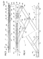
- - la figure 1 représente une vue schématisée et en plan d'un support d'angle conforme à l'invention et appliqué à une porte ou fenêtre dont le châssis ouvrant est en position d'ouverture à la française ;
- - la figure 2 représente une vue schématisée et en coupe du support d'angle représenté dans la figure 1 ;
- - la figure 3 représente une vue schématisée en élévation et en coupe d'un compas d'arrêt réalisé selon l'invention et appliqué à une porte ou fenêtre dont le châssis ouvrant est en position d'abattant ;
- - la figure 4 représente une vue schématisée et en plan du compas d'arrêt représenté dans la figure 3 ;
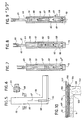
- - la figure 5 représente une vue schématisée et en élévation de l'équerre venant se fixer dans l'angle inférieur du châssis ouvrant et formant l'un des éléments constitutifs des moyens d'articulation reliant le bras de compas auxiliaire audit châssis ouvrant ;
- - la figure 6 représente une vue en coupe selon VI-VI de la figure 5 ;
- - la figure 7 représente une vue schématisée et en coupe des moyens d'articulation reliant, au niveau du support d'angle le bras de compas auxiliaire au châssis ouvrant, ce dernier étant en position verrouillée ;
- - la figure 8 représente une vue identique à la figure 7, l'ouvrant étant en position d'ouverture à la française ;
- - la figure 9 représente une vue identique aux figures 6 et 7 précédentes, l'ouvrant étant en position d'ouverture en abattant ;
- - la figure 10 représente une vue de détail de l'angle supérieur du châssis ouvrant représenté sous forme schématisée et en coupe.
- - Figure 1 shows a schematic plan view of a corner support according to the invention and applied to a door or window whose opening frame is in the French open position;
- - Figure 2 shows a schematic sectional view of the corner support shown in Figure 1;
- - Figure 3 shows a schematic view in elevation and in section of a stop compass produced according to the invention and applied to a door or window whose opening frame is in the flap position;
- - Figure 4 shows a schematic plan view of the stop compass shown in Figure 3;
- - Figure 5 shows a schematic view in elevation of the bracket coming to be fixed in the lower corner of the opening frame and forming one of the constituent elements of the articulation means connecting the auxiliary compass arm to said opening frame;
- - Figure 6 shows a sectional view along VI-VI of Figure 5;
- - Figure 7 shows a schematic sectional view of the hinge means connecting, at the angle support the auxiliary compass arm to the opening frame, the latter being in the locked position;
- - Figure 8 shows a view identical to Figure 7, the opening being in the French open position;
- - Figure 9 shows a view identical to Figures 6 and 7 above, the opening being in the open position by folding;
- - Figure 10 shows a detail view of the upper corner of the opening frame shown in schematic form and in section.
Les ferrures d'articulation, conformes à l'invention et représentées dans les figures 1 à 4, s'appliquent à des portes ou fenêtres dont l'ouvrant 1 est du type oscillo-battant. Ainsi, cet ouvrant 1 est en mesure de pivoter autour d'un axe vertical, passant par le montant arrière 2 et correspondant à une position d'ouverture dite à la française. Par ailleurs, cet ouvrant 1 peut basculer autour d'un axe horizontal, matérialisé fréquemment, par sa traverse inférieure 3, une telle ouverture correspondant à la position en abattant.The hinge fittings, according to the invention and shown in Figures 1 to 4, apply to doors or windows whose opening 1 is of the tilt-and-turn type. Thus, this opening 1 is able to pivot about a vertical axis, passing through the
Parmi les différents ouvrants à caractère oscillo-battant, on distingue ceux à recouvrement partiel du cadre dormant 4. De tels ouvrants 1 possèdent, sur leur périphérie, un rebord 5 venant en applique, en position de fermeture, sur la face interne 6 dudit cadre dormant 4 et contribuant, ainsi, à une meilleure étanchéité de la porte ou fenêtre.Among the various tilt-and-turn opening elements, there are those with partial overlap of the sleeping frame 4. Such opening elements 1 have, on their periphery, a
La présente invention, s'applique, plus précisément, à de tels ouvrants et concerne des ferrures d'articulation prenant place en feuillures 7, 8 du cadre dormant 4 et du châssis ouvrant 9.The present invention applies, more precisely, to such opening and relates to articulation fittings taking place in
Ces ferrures d'articulation se composent d'un support d'angle assurant la liaison basse de l'ouvrant 1 au cadre dormant 4 et d'un compas d'arrêt 11 constituant la liaison haute de ces derniers. Ainsi, le support d'angle 10 permet, à la fois, de conférer à l'ouvrant 1 une rotation autour d'un axe vertical et une rotation autour d'un axe horizontal, tandis que le compas d'arrêt 11 assure le pivotement autour d'un axe vertical du compas principal 12 qui, en raison de sa liaison à l'ouvrant 1 répercute cette rotation sur ce dernier. Ce compas d'arrêt 11 permet, en outre, de limiter l'angle de basculement de l'ouvrant 1 lors de sa rotation autour de l'axe horizontal.These articulation fittings consist of a corner support ensuring the low connection of the opening 1 to the frame 4 and a
Plus exactement, le support d'angle 10, tel que représenté dans les figures 1 et 2 comporte, d'une part, un bras de compas auxiliaire 13 relié, à l'une de ses extrémités 14, et à l'aide de moyens d'articulation 15, à la traverse inférieure 3 du châssis ouvrant 9. Préférentiellement, cette liaison du bras de compas auxiliaire à l'ouvrant 1 se situe au plus près de l'angle inférieur 16 de ce dernier. Une articulation 17 raccorde le bras de compas auxiliaire 13 au cadre dormant 4 et, notamment, à un support 18 formé par une platine allongée 19 rapportée à l'aide d'éléments de fixation en feuillures 7, sur la traverse inférieure 21 dudit cadre dormant 4.More precisely, the
L'intérêt principal de ce bras de compas auxiliaire 13 consiste, lors de l'ouverture à la française, à dégager le montant arrière 2 de l'ouvrant 1 par rapport au montant arrière 22 du cadre dormant 4 et, simultanément, de déporter ledit ouvrant 1 suivant une direction perpendiculaire au plan vertical 23 de la porte ou fenêtre. Ce déport s'effectue, de préférence, vers l'intérieur de l'habitation.The main interest of this
Il convient, en effet, de remarquer qu en raison de la disposition en feuillures des ferrures d'articulation, il est indispensable de conférer à un ouvrant à recouvrement partiel du cadre dormant 4, une telle cinématique sans quoi son rebord périphérique 5, coopère avec la face interne 6 dudit cadre dormant 4 et empêche sa rotation autour d'un axe vertical et, de ce fait, l'ouverture à la française.It should, in fact, be noted that due to the arrangement of rebates of the articulation fittings, it is essential to confer on a sash partially overlapping the sleeping frame 4, such kinematics without which its
Le support d'angle 10, comporte, d'autre part, et selon une caractéristique de l'invention, un second bras de compas 24 reliant le châssis ouvrant 9 au cadre dormant 4. Plus précisément, ce bras de compas 24 est monté coulissant, à l'une de ses extrémités 25, sur la traverse inférieure 21 du cadre dormant 4, tandis que l'autre extrémité 26 est fixée, par une articulation 26A, en feuillure 8 et sur la traverse inférieure 3 du châssis ouvrant 9.The
Selon un mode de réalisation préférentiel, le montage coulissant de ce second bras de compas 24 sur le cadre dormant 4 est obtenu au moyen d'une glissière 27 aménagée dans le support 18 appliqué sur la traverse inférieure 21 dudit cadre dormant 4. Cette glissière 27 consiste, en fait, en une ouverture 28 de forme oblongue, aménagée dans la platine 19 et, notamment, dans sa partie avant 29 orientée vers le montant avant du cadre dormant 4. Dans l'ouverture 28 est engagé un tourillon 30 fixé à l'extrémité 25 du second bras de compas 24 et se présentant saillant par rapport à la face inférieure 31 de ce dernier. Ce tourillon 30 est muni, par ailleurs, à son extrémité libre 32, d'un flasque 33 coopérant avec le côté inférieur 34 de la platine 19. Il évite, ainsi, le dégagement inopiné du second bras de compas 24 de la glissière 27 lors de la manipulation de l'ouvrant 1.According to a preferred embodiment, the sliding mounting of this
Préférentiellement, des rebords 35, 36 sont aménagés sur le côté inférieur 34 de la platine 19, au niveau des bords longitudinaux 37, 38 de l'ouverture 28. Cette caractéristique permet d'améliorer, sensiblement, la qualité du guidage du tourillon 30 et contribuer, de ce fait, à une réduction des jeux existant entre les différentes pièces constitutives du support d'angle 10. On notera, cependant, qu'une telle amélioration ne se traduit, en aucun cas, par une augmentation de l'épaisseur de la platine 19. En effet, ces rebords 35, 36 pourront être obtenus par une simple opération d'emboutissage peu coûteuse.Preferably,
Avantageusement, le support d'angle 10 est également muni d'une biellette 39 montée articulée, à l'une de ses extrémités 40, sur le second bras de compas 24 et coopérant, au moyen d'une articulation 41, et à son extrémité opposée 42, avec le support 18 ou platine 19. Cette biellette 39 a pour fonction principale de répartir l'action des bras de compas 13 et 24 sur l'ouvrant 1. A cet effet, on notera que l'articulation 41, reliant cette biellette 39 au support 18, se situe, de préférence, entre l'ouverture 28 et les moyens d'articulation 15 du bras de compas auxiliaire 13. En fait, l'articulation 41 de la biellette 39 est disposée au plus près de ces moyens d'articulation 15 pour autoriser un angle d'ouverture de l'ouvrant 1 le plus important possible. En raison des caractéristiques de la présente invention, cet angle d'ouverture de l'ouvrant 1 peut atteindre des valeurs largement supérieures à quatre vingt dix degrés.Advantageously, the
A noter, par ailleurs, qu'en position perpendiculaire au plan vertical 23 de la porte ou fenêtre, l'ouvrant 1 comporte des points d'attache au cadre dormant 4 relativement éloignés les uns des autres. Il conserve, par là même, une stabilité irréprochable quel que soit son poids et sa taille.Note, moreover, that in position perpendicular to the
Selon un mode d'exécution préférentiel de l'invention, le second bras de compas 24 est cambré en son milieu 43 autorisant l'insertion de la biellette 39 entre ledit second bras de compas 24 et la platine 19, en position de fermeture de l'ouvrant 1. Toutefois, il est pris soin que l'épaisseur globale 44 du support d'angle 10 soit maintenue inférieure au jeu existant entre les feuillures 7, 8 du cadre dormant 4 et du châssis ouvrant 9 de manière à éviter un entaillage quelconque de l'un de ces derniers.According to a preferred embodiment of the invention, the
Quant au bras de compas auxiliaire 13, situé, en position de fermeture de l'ouvrant 1, dans le prolongement du second bras de compas 24 et de la biellette 39, il est choisi d'épaisseur 45 équivalente à la somme de ces derniers. Ainsi, renforcé, ce bras de compas auxiliaire 13 est en mesure de supporter le poids que constitue l'ouvrant 1 lorsque celui-ci est déporté en dehors du plan vertical 23 de la porte ou fenêtre.As for the
Dans ce même but de résistance mécanique du support d'angle 10, en cas d'application à des ouvrants de taille et de poids importants, l'articulation 17 raccordant le bras de compas auxiliaire 13 au cadre dormant 4 est formée par un axe vertical 46 introduit largement dans la traverse inférieure 21 de ce dernier. De plus, l'extrémité 47 de cet axe vertical 46, se présentant saillante par rapport au support 18, est engagée dans un alésage 48 aménagé à l'extrémité 17A dudit bras de compas auxiliaire 13.For the same purpose of mechanical strength of the
En ce qui concerne le compas d'arrêt 11, hormis le bras de compas principal 12, il reprend une structure sensiblement identique au support d'angle 10. Ainsi, tel que représenté dans les figures 3 et 4, il comporte un bras de compas auxiliaire 113, relié, à l'une de ses extrémités 114 et au moyen d'une articulation 115, à l'extrémité arrière 116 dudit bras de compas principal 12. Par ailleurs, une articulation 117 assure la liaison de ce bras de compas auxiliaire 113 à son extrémité opposée, avec un support 118 formé par une platine allongée 119 rendue solidaire, au moyen d'éléments de fixation 120 en feuillure 7, sur la traverse supérieure 121 du cadre dormant 4.Regarding the
Ce compas d'arrêt 11 est également pourvu d'un second bras de compas 124 dont une extrémité 125 est montée coulissante dans une glissière 127 aménagée dans le support 118. L'autre extrémité 126 de ce second bras de compas 124 est rendue solidaire du bras de compas principal 12 à l'aide d'une articulation 126A.This
La structure de la glissière 127 est identique à celle décrite dans le cadre du support d'angle 10. Ainsi, elle est formée par une ouverture de forme oblongue 128 aménagée dans la platine 119. Celle-ci comporte, sur sa face 134, orientée en direction de la traverse supérieure 121 du cadre dormant 4, des rebords 135, 136, situés sur les bords longitudinaux 137, 138 de l'ouverture 128. Dans cette glissière 127 est engagé un tourillon 130 solidaire de l'extrémité 125 du second bras de compas 124, tourillon 130, comportant à son extrémité libre 132, un flasque 133 coopérant avec les rebords 135, 136 et empêchant son dégagement de l'ouverture 128.The structure of the
Une biellette 139, montée articulée à l'une de ses extrémités 140 sur le second bras de compas 124, relie, également, ce dernier à la traverse supérieure 121 du cadre dormant 4. A cet effet, cette biellette 139 coopère, à son extrémité 142, avec le support 118 au moyen d'une articulation 141 disposée à proximité immédiate de l'articulation 117 reliant, à ce même support 118, le bras de compas auxiliaire 113.A
Là encore, le second bras de compas 124 comporte, en son milieu 143, une cambrure autorisant, en position de fermeture, l'engagement de la biellette 139 entre ledit second bras de compas 124 et la platine 119. Toutefois, on notera que le bras de compas auxiliaire 113 n'est pas nécessairement renforcé étant donné qu'il ne contribue que pour une faible partie au support du poids de l'ouvrant. Dans ces conditions, l'écart 144 existant entre ledit bras de compas auxiliaire 113 et la platine 119 est compensé par un bossage 145 sur la face inférieure 146 de cette dernière et sur lequel est montée l'articulation 117.Again, the
Il convient de noter que, dans le cadre du support d'angle 10 tout comme de ce compas d'arrêt 11, les articulations 17, 117 et 41, 141, reliant le bras de compas auxiliaire 13; 113 et la biellette 39, 139 au support 18, 118 sont rapprochées au maximum l'une de l'autre et disposées au plus près du montant arrière 22 du cadre dormant 4.It should be noted that, within the framework of the
Quant au bras de compas principal 12, celui-ci est relié à l'ouvrant 1 selon des techniques connues par l'Homme du Métier. Ainsi, l'extrémité avant 147 est munie d'un tourillon (non représenté) monté coulissant dans une lumière oblongue 148 aménagée dans une têtière 149 disposée en feuillure 8 sur la traverse supérieure 150 du châssis ouvrant 9. Plus précisément, cette têtière 149 recouvre une rainure 151 réalisée en périphérie de l'ouvrant 1, et dans laquelle coulissent des tringles de manoeuvre actionnées par un mécanisme de verrouillage, tel qu'une crémone ou crémone-serrure. De plus, une biellette 152 relie le bras de compas principal 12 au châssis ouvrant 9, empêchant celui-ci à se décaler par rapport au cadre dormant 4 en cas d'ouverture en abattant.As for the
Le maintien du bras de compas principal 12 sur la têtière 149 en position d'ouverture à la française peut être assuré par tout moyen connu tel que des gâches solidaires dudit bras de compas principal 12. Ces gâches sont ainsi en mesure de coopérer avec des organes de verrouillage fixés sur une tringle de manoeuvre et émergeant de la têtière 149 au travers d'ouvertures réalisées à cet effet. Toutefois, en raison de l'encombrement du compas d'arrêt 11 en feuillures 7, 8 du cadre dormant 4 et du châssis ouvrant 9, il serait nécessaire de décaler fortement les gâches précitées par rapport à l'axe de rotation vertical de l'ouvrant 1. Or, dans de telles conditions, le moindre jeu existant entre la gâche et l'organe de verrouillage disposé sur la tringle de manoeuvre se traduit, pour des ouvrants de largeur importante, par un jeu de plusieurs millimètres au niveau de leur montant arrière.Maintaining the
Pour remédier à un tel inconvénient, on prolonge, tel que représenté dans la figure 10, l'extrémité arrière 116 du bras de compas principal 12 par un tronçon replié en forme d'équerre 155 venant, en position d'ouverture à la française, coiffer l'angle supérieur 153 du châssis ouvrant 9 et, notamment, de la têtière 149. Dans l'aile verticale 156 de ce tronçon replié en forme d'équerre 155 est réalisée une lumière 157 dans laquelle s'engage l'extrémité 158 d'une tringle de manoeuvre 159 émergeant du chant vertical arrière 154 dudit châssis ouvrant 9. Contrairement, la commande de la crémone ou crémone-serrure, lors de l'ouverture en abattant, provoque le retrait de cette extrémité saillante 158 de la tringle de manoeuvre 159 libérant, ainsi, le bras de compas principal 12.To remedy such a drawback, the
En ce qui concerne le pivotement du châssis ouvrant 9 par rapport au cadre dormant 4, selon un axe de rotation horizontal, il peut être rendu possible, grâce à un jeu suffisant au niveau de l'articulation 17 reliant le bras de compas auxiliaire 13 au support 18.As regards the pivoting of the
Plus précisément, l'extrémité saillante 47 de l'axe 46, auquel il a été fait référence plus haut dans la description, est de forme conique et introduite dans l'alésage 48 aménagé dans l'extrémité 17A du bras de compas auxiliaire 13. Une telle configuration autorise le pivotement, selon un angle limité, de ce dernier autour d'un axe horizontal.More specifically, the projecting
Dans ces conditions, les moyens d'articulation 15 reliant ce même bras de compas auxiliaire 13 à l'ouvrant 1, sont constitués, par un axe vertical 49 rendu solidaire, à son extrémité inférieure 50, de l'extrémité libre 14 dudit bras de compas auxiliaire 13. De plus, une équerre 52 coiffe l'angle inférieur 16 de l'ouvrant 1 et s'inscrit dans des entaillages 53, 54 aménagés dans le montant arrière 2 et la traverse inférieure 3 de l'ouvrant 1 et servant, habituellement, au logement des tringles de manoeuvre et de la têtière. Cette équerre 52 est rendue solidaire de l'ouvrant 1 au moyen d'éléments de fixation tels que vis ou analogue et comporte, dans son chant inférieur 55 et dans l'angle 56, un évidement cylindrique 57 aux dimensions ajustées à celles de l'axe 49 pour autoriser le passage et la rotation de ce dernier.Under these conditions, the articulation means 15 connecting this same
Dans certains cas, notamment pour des gammes d'ouvrants plus ou moins importants, un tel jeu au niveau de la liaison du bras de compas auxiliaire 13 sur le support 18 peut représenter un inconvénient étant à l'origine d'une fatigue plus rapide des pièces constitutives des ferrures d'articulation.In certain cases, in particular for ranges of more or less significant opening, such a clearance at the level of the connection of the
Dans ces conditions, et selon un autre mode d'exécution, conforme à l'invention, et représenté dans les figures 5 à 9, l'extrémité saillante 47 de l'axe 46 est ajustée au diamètre de l'alésage 48 présent dans le bras de compas auxiliaire 13 de sorte que seule la rotation autour d'un axe horizontal de ce dernier soit autorisée.Under these conditions, and according to another embodiment, in accordance with the invention, and represented in FIGS. 5 to 9, the projecting
De plus, l'axe vertical 49 constituant, en partie, les moyens d'articulation 15 dudit bras de compas auxiliaire 13 au châssis ouvrant 9, est introduit dans une ouverture oblongue 57A usinée dans le chant inférieur 55 et dans l'angle 56 de l'équerre 52. Cette ouverture oblongue 57A communique avec un évidement 58, de préférence de forme cylindrique, d'axe vertical et réalisé dans l'aile verticale 59 de ladite équerre 52. Une douille 60, solidaire d'une tige de transmission 61, coulisse dans cet évidement 58 et coopère avec l'axe vertical 49.In addition, the
Plus précisément, la douille 60 présente sur sa face inférieure 62 un trou borgne 63 ajusté au diamètre de l'axe vertical 49 pour en autoriser l'introduction.More specifically, the
Quant à la tige de transmission 61, connectée à la douille 60, elle débouche de l'évidement 58, au niveau du chant supérieur 64 de l'aile verticale 59 correspondant à l'équerre 52. Cette tige de transmission 61 est, ainsi, en mesure de coopérer, à son extrémité supérieure 65 et à l'aide de moyens de liaison 66, avec une tringle de manoeuvre (non représentée). Celle-ci est logée dans l'entaillage 53 présent dans le montant arrière 2 de l'ouvrant 1 et coopère avec le mécanisme de verrouillage, tel que crémone ou crémone-serrure.As for the
De ce fait, sous l'action de cette tringle de manoeuvre, commandée par ledit mécanisme de verrouillage, la douille 60 est amenée à coulisser dans l'évidement 58 de l'équerre 52 coopérant ou non, selon le cas, avec l'axe vertical 49. Plus exactement, en position de fermeture de l'ouvrant 1, correspondant à la figure 7, la douille 60 est totalement engagée sur l'axe vertical 49. En actionnant le mécanisme de verrouillage, pour commander l'ouverture à la française de la porte ou fenêtre, le jeu des tringles de manoeuvre provoque la montée de la douille 60, celle-ci étant maintenue en position partiellement engagée sur l'axe vertical 49, tel que visible dans la figure 8. Cet axe vertical 49 est, dans ce cas, en mesure de pivoter autour d'un axe vertical.Therefore, under the action of this operating rod, controlled by said locking mechanism, the
Finalement, en position d'ouverture en abattant de l'ouvrant 1, correspondant à la configuration des moyens d'articulation tels que représentés dans la figure 9, la douille 60 est totalement relevée dans l'évidement 58, libérant l'axe vertical 49.Finally, in the open position by opening the opening 1, corresponding to the configuration of the articulation means as shown in Figure 9, the
De ce fait, et en raison de l'ouverture de forme oblongue 57A aménagée dans l'équerre 52, cette dernière est apte à pivoter autour d'un axe horizontal. Toutefois, pour éviter de limiter le déplacement angulaire de l'axe vertical 49 à l'intérieur de l'évidement 58, l'équerre 52 et, notamment, l'aile verticale 59 présente, à proximité de l'angle 56 et sur sa face 67 orientée vers l'extérieur de la porte ou fenêtre, une ouverture 68. Cette dernière, ainsi disposée au droit de l'axe vertical 49, permet à l'extrémité libre 69 de celui-ci d'émerger de l'équerre 52 en position de basculement maximum de l'ouvrant 1.Therefore, and due to the oblong opening 57A arranged in the
Il est indéniable qu'une telle configuration améliore la tenue du châssis ouvrant 9 par rapport au cadre dormant 4, en cas d'ouverture à la française de la porte ou fenêtre.It is undeniable that such a configuration improves the holding of the
En conséquence, le support d'angle 10 et le compas d'arrêt 11, objets de la présente invention, apportent des avantages incontestables dans le domaine des ferrures d'articulation encastrées pour porte ou fenêtre oscillo-battantes. En effet, leur conception particulière autorise leur application à des ouvrants de taille et de poids importants avec une fiabilité irréprochable et tout en assurant un angle d'ouverture à la française supérieur à quatre vingt dix degrés. Ces ferrures d'articulation, conformes à l'invention, associent, ainsi, efficacité et esthétique.Consequently, the
Claims (15)
- un second bras de compas (24, 124) monté coulissant, à une de ses extrémités (25, 125), sur la traverse inférieure (21), respectivement, supérieure (121) du cadre dormant (4) et dont l'autre extrémité (26, 126) est reliée au moyen d'une articulation (26A, 126A) à la traverse inférieure (3) du châssis ouvrant (9), respectivement, au bras de compas principal (12) ;
- et une biellette (39, 139) dont une extrémité (40, 140), est montée articulée sur le second bras de compas (24, 124) et dont l'autre extrémité est fixée pivotante sur la traverse inférieure (21) respectivement, supérieure (121) dudit cadre dormant (4) .1. Hinge fittings for door, window or the like, tilt-and-turn and the opening frame (9) of which is partially overlapping the frame (4), composed of a corner support (10) and a stop compass (11) fixed in rebates (7, 8) and both comprising an auxiliary compass arm (13, 113) connected, on the one hand, to the lower cross member (21), respectively, upper ( 121) of the fixed frame (4) and, on the other hand, to the lower cross member (3) of the opening frame (9), respectively, to a main compass arm (12) cooperating with the upper cross member (150) of this last, articulation fittings characterized by the fact that the angle support (10) and the stop compass (11) comprise:
- A second compass arm (24, 124) mounted to slide, at one of its ends (25, 125), on the lower crosspiece (21), respectively, upper (121) of the frame (4) and the other of which end (26, 126) is connected by means of an articulation (26A, 126A) to the lower cross member (3) of the opening frame (9), respectively, to the main compass arm (12);
- And a link (39, 139), one end (40, 140) of which is articulated on the second compass arm (24, 124) and the other end of which is pivotally attached to the lower cross member (21) respectively, upper (121) of said sleeping frame (4).
Priority Applications (1)
| Application Number | Priority Date | Filing Date | Title |
|---|---|---|---|
| AT89440048T ATE71695T1 (en) | 1988-06-13 | 1989-06-02 | TILT-TURN HARDWARE FOR DOORS, WINDOWS OR ANALOGUE WITH PARTIAL COVERING OF THE WINDOW FRAME BY THE WINDOW SASH. |
Applications Claiming Priority (2)
| Application Number | Priority Date | Filing Date | Title |
|---|---|---|---|
| FR8808046 | 1988-06-13 | ||
| FR8808046A FR2632679B1 (en) | 1988-06-13 | 1988-06-13 | ARTICULATING HARDWARE FOR DOOR, WINDOW OR THE LIKE, SWINGING |
Publications (2)
| Publication Number | Publication Date |
|---|---|
| EP0347352A1 true EP0347352A1 (en) | 1989-12-20 |
| EP0347352B1 EP0347352B1 (en) | 1992-01-15 |
Family
ID=9367348
Family Applications (1)
| Application Number | Title | Priority Date | Filing Date |
|---|---|---|---|
| EP89440048A Expired - Lifetime EP0347352B1 (en) | 1988-06-13 | 1989-06-02 | Fitting or a pivoting and tiltable wing of a door, window or the like with a sash which partially covers the window frame |
Country Status (9)
| Country | Link |
|---|---|
| US (1) | US5037230A (en) |
| EP (1) | EP0347352B1 (en) |
| JP (1) | JPH0238681A (en) |
| KR (1) | KR910001204A (en) |
| AT (1) | ATE71695T1 (en) |
| DE (1) | DE68900710D1 (en) |
| ES (1) | ES2029132T3 (en) |
| FR (1) | FR2632679B1 (en) |
| GR (1) | GR3004083T3 (en) |
Cited By (2)
| Publication number | Priority date | Publication date | Assignee | Title |
|---|---|---|---|---|
| DE9000152U1 (en) * | 1990-01-09 | 1990-03-15 | August Bilstein GmbH & Co KG, 5828 Ennepetal | Lower corner bearing for pivoting, especially tilt/turn windows, doors, etc. |
| WO2008083810A1 (en) * | 2007-01-12 | 2008-07-17 | Roto Frank Ag | Window, door, or the like having a fitting assembly with a mount projection and associated counter surface |
Families Citing this family (8)
| Publication number | Priority date | Publication date | Assignee | Title |
|---|---|---|---|---|
| AU631534B2 (en) * | 1989-02-15 | 1992-12-03 | Vkr Holding A/S | A window with a main frame for installation in an inclined roof and two openable window frames |
| WO2002029192A2 (en) * | 2000-10-06 | 2002-04-11 | Caldwell Manufacturing Company | Hinge system for opening windows |
| CN2486689Y (en) * | 2001-07-18 | 2002-04-17 | 陆中选 | Improved slide flat-open multifunction combined window |
| US20080016781A1 (en) * | 2006-07-21 | 2008-01-24 | Kuan-Chin Chung | Connecting assembly for pushing outward window frame |
| DE102012211886A1 (en) * | 2012-07-06 | 2014-01-09 | Technische Universität Berlin | Medical instrument and method for pivoting such a medical instrument |
| BE1023748B1 (en) * | 2016-01-07 | 2017-07-11 | PARYS Emmanuel Diederich Camille VAN | INDEPENDENT HINGE FOR A TURN-CHICKEN AND CHICKEN-TURN WINDOW AND WINDOW EQUIPPED FOR THAT |
| CN112922477A (en) * | 2021-02-01 | 2021-06-08 | 揭阳市揭东英特兴业五金制品有限公司 | Wind-resistant bearing door and window sliding support hinge |
| PL440752A1 (en) * | 2022-03-24 | 2023-09-25 | Fakro Pp Spółka Z Ograniczoną Odpowiedzialnością | Hinge connecting the fixed and movable components of a structural element, especially attic stairs |
Citations (5)
| Publication number | Priority date | Publication date | Assignee | Title |
|---|---|---|---|---|
| DE2940049A1 (en) * | 1979-10-03 | 1981-05-14 | August Bilstein GmbH & Co KG, 5828 Ennepetal | Tilt and turn window wing extension mechanism - has control arm guiding slot outside support guide rod swivel area |
| DE8117446U1 (en) * | 1981-06-12 | 1981-10-01 | August Bilstein GmbH & Co KG, 5828 Ennepetal | Opening device for turn-tilt sashes of windows, doors or the like. |
| EP0112681A1 (en) * | 1982-12-24 | 1984-07-04 | Securistyle Limited | Improvement in friction supporting stays |
| EP0204267A2 (en) * | 1985-06-07 | 1986-12-10 | Siegenia-Frank Kg | Fitting arrangement for tiltable wings of windows, doors or the like |
| DE3601278A1 (en) * | 1986-01-17 | 1987-07-30 | Hautau Gmbh W | HIDDEN IN FOLDING FITTING FOR SWIVEL BEARINGS, IN PART. FOR TILT-SWING WING OF WINDOWS OR DOORS |
Family Cites Families (8)
| Publication number | Priority date | Publication date | Assignee | Title |
|---|---|---|---|---|
| DE204267C (en) * | ||||
| GB112681A (en) * | 1917-02-01 | 1918-01-24 | Maud Alice Christine | Improvements in Slide Rules. |
| US2921819A (en) * | 1957-02-28 | 1960-01-19 | R B Leonard Inc | Combination pivot pin and bushing device |
| US3797169A (en) * | 1972-10-19 | 1974-03-19 | Truth Inc | Window hinge |
| US4364201A (en) * | 1980-09-15 | 1982-12-21 | A. W. Anderberg Manufacturing Co. | Full-opening window linkage assembly |
| NZ212598A (en) * | 1985-06-28 | 1992-09-25 | Ronald Percival Davis | Window stay with friction pivot joints at pivotal connections and mountings and a control arm connected from lower arm to first of two upper arms from intermediate their ends |
| DE8705069U1 (en) * | 1987-04-04 | 1987-05-27 | Siegenia-Frank Kg, 5900 Siegen | Limit stop for the swivel angle of an arm moving around a bearing axis |
| US4833754A (en) * | 1988-09-26 | 1989-05-30 | Yang Wu N | Supporting bracket for windows |
-
1988
- 1988-06-13 FR FR8808046A patent/FR2632679B1/en not_active Expired - Fee Related
-
1989
- 1989-06-02 DE DE8989440048T patent/DE68900710D1/en not_active Expired - Lifetime
- 1989-06-02 EP EP89440048A patent/EP0347352B1/en not_active Expired - Lifetime
- 1989-06-02 AT AT89440048T patent/ATE71695T1/en not_active IP Right Cessation
- 1989-06-02 ES ES198989440048T patent/ES2029132T3/en not_active Expired - Lifetime
- 1989-06-07 US US07/362,655 patent/US5037230A/en not_active Expired - Fee Related
- 1989-06-13 KR KR1019890008177A patent/KR910001204A/en not_active Application Discontinuation
- 1989-06-13 JP JP1148520A patent/JPH0238681A/en active Pending
-
1992
- 1992-03-18 GR GR920400487T patent/GR3004083T3/el unknown
Patent Citations (5)
| Publication number | Priority date | Publication date | Assignee | Title |
|---|---|---|---|---|
| DE2940049A1 (en) * | 1979-10-03 | 1981-05-14 | August Bilstein GmbH & Co KG, 5828 Ennepetal | Tilt and turn window wing extension mechanism - has control arm guiding slot outside support guide rod swivel area |
| DE8117446U1 (en) * | 1981-06-12 | 1981-10-01 | August Bilstein GmbH & Co KG, 5828 Ennepetal | Opening device for turn-tilt sashes of windows, doors or the like. |
| EP0112681A1 (en) * | 1982-12-24 | 1984-07-04 | Securistyle Limited | Improvement in friction supporting stays |
| EP0204267A2 (en) * | 1985-06-07 | 1986-12-10 | Siegenia-Frank Kg | Fitting arrangement for tiltable wings of windows, doors or the like |
| DE3601278A1 (en) * | 1986-01-17 | 1987-07-30 | Hautau Gmbh W | HIDDEN IN FOLDING FITTING FOR SWIVEL BEARINGS, IN PART. FOR TILT-SWING WING OF WINDOWS OR DOORS |
Cited By (2)
| Publication number | Priority date | Publication date | Assignee | Title |
|---|---|---|---|---|
| DE9000152U1 (en) * | 1990-01-09 | 1990-03-15 | August Bilstein GmbH & Co KG, 5828 Ennepetal | Lower corner bearing for pivoting, especially tilt/turn windows, doors, etc. |
| WO2008083810A1 (en) * | 2007-01-12 | 2008-07-17 | Roto Frank Ag | Window, door, or the like having a fitting assembly with a mount projection and associated counter surface |
Also Published As
| Publication number | Publication date |
|---|---|
| ES2029132T3 (en) | 1992-07-16 |
| FR2632679B1 (en) | 1994-03-11 |
| KR910001204A (en) | 1991-01-30 |
| GR3004083T3 (en) | 1993-03-31 |
| DE68900710D1 (en) | 1992-02-27 |
| FR2632679A1 (en) | 1989-12-15 |
| ATE71695T1 (en) | 1992-02-15 |
| EP0347352B1 (en) | 1992-01-15 |
| US5037230A (en) | 1991-08-06 |
| JPH0238681A (en) | 1990-02-08 |
Similar Documents
| Publication | Publication Date | Title |
|---|---|---|
| EP0857844B1 (en) | Guiding device for a sliding and swaying wing closing an opening | |
| EP0364379B1 (en) | Fitting for a pivoting and tiltable wing of a door, window or the like, situated in the grooves of a window | |
| EP0347352B1 (en) | Fitting or a pivoting and tiltable wing of a door, window or the like with a sash which partially covers the window frame | |
| EP0290362B1 (en) | Fitting for a pivoting and tiltable wing of a door, window or the like | |
| EP0493225A1 (en) | Pivoting side door for motor vehicle | |
| EP0200649A1 (en) | Glass door with hinged frame for a vehicle | |
| EP0362095B1 (en) | Fitting for a door, window or the like | |
| EP1470012B1 (en) | Rear boot hood for an open-top vehicle with a folding roof | |
| WO2005012018A1 (en) | Rear deck hood with double-lock articulation for convertible vehicle with folding roof | |
| CA2026176A1 (en) | Compass bearing for winged sash of doors, windows and the like | |
| EP0924377B1 (en) | Hinge fitting for door, window or similar | |
| EP1004737B1 (en) | Lifting device for a sash of a door, window or the like | |
| FR2667647A1 (en) | Manoeuvrable system for stopping a shutter leaf and assembly for hooking the said leaf | |
| WO2003104007A1 (en) | Rear deck hood for folding roof vehicle | |
| FR2923756A1 (en) | Lockable and unlockable pivoting assembly e.g. front pivoting assembly, for bonnet in convertible vehicle, has hook mounted on base, and wall carried by male element of casing such that locking device releasably locks casing and base | |
| FR2810363A1 (en) | LIFT DEVICE FOR OPENING DOOR, WINDOW OR THE LIKE | |
| EP1151880A1 (en) | Convertible door for motor vehicle | |
| EP1672154A2 (en) | Closure device with controlled position for a wing on a wing frame | |
| EP0769602B1 (en) | Hinge for a door, window or the like | |
| FR2806437A1 (en) | Fastening system for tilting window in building has hinges at side permitting tilting about vertical axis and at bottom allowing tilting about horizontal axis | |
| FR2672334A1 (en) | HINGE FITTING FOR A DOOR, WINDOW OR THE LIKE, THE OPENING OF WHICH HAS TO PIVOT OUTWARD AND AROUND A VERTICAL AXIS WITH RESPECT TO A SLEEPING FRAME. | |
| FR2797656A1 (en) | Door hinge assembly for motor vehicle has movable body panel section to allow free movement of door hinge | |
| EP0805250B1 (en) | Stay for door, window or the like | |
| FR2846604A1 (en) | Locking device for rear boot lid for vehicle with folding roof comprises hook pivoted by motor about spindle whose free end is supported in body connected to lid | |
| FR2685379A1 (en) | Articulation fittings located in the rebate of a door, window or the like |
Legal Events
| Date | Code | Title | Description |
|---|---|---|---|
| PUAI | Public reference made under article 153(3) epc to a published international application that has entered the european phase |
Free format text: ORIGINAL CODE: 0009012 |
|
| AK | Designated contracting states |
Kind code of ref document: A1 Designated state(s): AT BE CH DE ES GB GR IT LI NL SE |
|
| 17P | Request for examination filed |
Effective date: 19900123 |
|
| 17Q | First examination report despatched |
Effective date: 19910612 |
|
| GRAA | (expected) grant |
Free format text: ORIGINAL CODE: 0009210 |
|
| AK | Designated contracting states |
Kind code of ref document: B1 Designated state(s): AT BE CH DE ES GB GR IT LI NL SE |
|
| REF | Corresponds to: |
Ref document number: 71695 Country of ref document: AT Date of ref document: 19920215 Kind code of ref document: T |
|
| ITF | It: translation for a ep patent filed | ||
| REF | Corresponds to: |
Ref document number: 68900710 Country of ref document: DE Date of ref document: 19920227 |
|
| GBT | Gb: translation of ep patent filed (gb section 77(6)(a)/1977) | ||
| PGFP | Annual fee paid to national office [announced via postgrant information from national office to epo] |
Ref country code: AT Payment date: 19920610 Year of fee payment: 4 |
|
| PGFP | Annual fee paid to national office [announced via postgrant information from national office to epo] |
Ref country code: SE Payment date: 19920615 Year of fee payment: 4 Ref country code: CH Payment date: 19920615 Year of fee payment: 4 |
|
| PGFP | Annual fee paid to national office [announced via postgrant information from national office to epo] |
Ref country code: GR Payment date: 19920616 Year of fee payment: 4 |
|
| PGFP | Annual fee paid to national office [announced via postgrant information from national office to epo] |
Ref country code: ES Payment date: 19920618 Year of fee payment: 4 |
|
| PGFP | Annual fee paid to national office [announced via postgrant information from national office to epo] |
Ref country code: NL Payment date: 19920630 Year of fee payment: 4 |
|
| REG | Reference to a national code |
Ref country code: ES Ref legal event code: FG2A Ref document number: 2029132 Country of ref document: ES Kind code of ref document: T3 |
|
| PGFP | Annual fee paid to national office [announced via postgrant information from national office to epo] |
Ref country code: BE Payment date: 19920903 Year of fee payment: 4 |
|
| PLBI | Opposition filed |
Free format text: ORIGINAL CODE: 0009260 |
|
| PLBI | Opposition filed |
Free format text: ORIGINAL CODE: 0009260 |
|
| 26 | Opposition filed |
Opponent name: SIEGENIA-FRANK KG Effective date: 19920930 Opponent name: HOESCH AG, Effective date: 19920922 |
|
| 26 | Opposition filed |
Opponent name: ROTO FRANK AG Effective date: 19921013 Opponent name: SIEGENIA-FRANK KG Effective date: 19920930 Opponent name: HOESCH AG, Effective date: 19920922 |
|
| REG | Reference to a national code |
Ref country code: GR Ref legal event code: FG4A Free format text: 3004083 |
|
| NLR1 | Nl: opposition has been filed with the epo |
Opponent name: SIEGENIA-FRANK KG Opponent name: HOESCH AG |
|
| NLR1 | Nl: opposition has been filed with the epo |
Opponent name: ROTO FRANK AG |
|
| PLAB | Opposition data, opponent's data or that of the opponent's representative modified |
Free format text: ORIGINAL CODE: 0009299OPPO |
|
| PG25 | Lapsed in a contracting state [announced via postgrant information from national office to epo] |
Ref country code: GB Effective date: 19930602 Ref country code: AT Effective date: 19930602 |
|
| PG25 | Lapsed in a contracting state [announced via postgrant information from national office to epo] |
Ref country code: SE Effective date: 19930603 Ref country code: ES Free format text: LAPSE BECAUSE OF NON-PAYMENT OF DUE FEES Effective date: 19930603 |
|
| PG25 | Lapsed in a contracting state [announced via postgrant information from national office to epo] |
Ref country code: LI Free format text: LAPSE BECAUSE OF NON-PAYMENT OF DUE FEES Effective date: 19930630 Ref country code: CH Free format text: LAPSE BECAUSE OF NON-PAYMENT OF DUE FEES Effective date: 19930630 Ref country code: BE Effective date: 19930630 |
|
| R26 | Opposition filed (corrected) |
Opponent name: FRIED. KRUPP AG HOESCH-KRUPP * 920930 SIEGENIA-FRA Effective date: 19920922 |
|
| PGFP | Annual fee paid to national office [announced via postgrant information from national office to epo] |
Ref country code: DE Payment date: 19930824 Year of fee payment: 5 |
|
| NLXE | Nl: other communications concerning ep-patents (part 3 heading xe) |
Free format text: PAT.BUL.02/93 CORR.:FRIED. KRUPP AG HOESCH-KRUPP |
|
| BERE | Be: lapsed |
Owner name: FERCO INTERNATIONAL USINE DE FERRURES DE BATIMENT Effective date: 19930630 |
|
| PG25 | Lapsed in a contracting state [announced via postgrant information from national office to epo] |
Ref country code: GR Free format text: THE PATENT HAS BEEN ANNULLED BY A DECISION OF A NATIONAL AUTHORITY Effective date: 19931231 |
|
| PG25 | Lapsed in a contracting state [announced via postgrant information from national office to epo] |
Ref country code: NL Effective date: 19940101 |
|
| GBPC | Gb: european patent ceased through non-payment of renewal fee |
Effective date: 19930602 |
|
| NLV4 | Nl: lapsed or anulled due to non-payment of the annual fee | ||
| REG | Reference to a national code |
Ref country code: CH Ref legal event code: PL |
|
| RDAC | Information related to revocation of patent modified |
Free format text: ORIGINAL CODE: 0009299REVO |
|
| RDAG | Patent revoked |
Free format text: ORIGINAL CODE: 0009271 |
|
| STAA | Information on the status of an ep patent application or granted ep patent |
Free format text: STATUS: PATENT REVOKED |
|
| 27W | Patent revoked |
Effective date: 19940310 |
|
| R27W | Patent revoked (corrected) |
Effective date: 19940310 |
|
| REG | Reference to a national code |
Ref country code: GR Ref legal event code: MM2A Free format text: 3004083 |
|
| EUG | Se: european patent has lapsed |
Ref document number: 89440048.0 Effective date: 19940110 |