EP0204128B1 - Steckverbindung für Bohrgestänge von Erdbohrgeräten - Google Patents
Steckverbindung für Bohrgestänge von Erdbohrgeräten Download PDFInfo
- Publication number
- EP0204128B1 EP0204128B1 EP86105704A EP86105704A EP0204128B1 EP 0204128 B1 EP0204128 B1 EP 0204128B1 EP 86105704 A EP86105704 A EP 86105704A EP 86105704 A EP86105704 A EP 86105704A EP 0204128 B1 EP0204128 B1 EP 0204128B1
- Authority
- EP
- European Patent Office
- Prior art keywords
- chain
- annulus
- female part
- male
- multilink
- Prior art date
- Legal status (The legal status is an assumption and is not a legal conclusion. Google has not performed a legal analysis and makes no representation as to the accuracy of the status listed.)
- Expired - Lifetime
Links
- 238000005553 drilling Methods 0.000 title abstract description 5
- 230000008878 coupling Effects 0.000 claims abstract description 22
- 238000010168 coupling process Methods 0.000 claims abstract description 22
- 238000005859 coupling reaction Methods 0.000 claims abstract description 22
- 229910000831 Steel Inorganic materials 0.000 claims description 21
- 239000010959 steel Substances 0.000 claims description 21
- 229910000639 Spring steel Inorganic materials 0.000 claims description 4
- 239000007787 solid Substances 0.000 claims description 3
- 230000000903 blocking effect Effects 0.000 claims 1
- 229910000679 solder Inorganic materials 0.000 claims 1
- 238000011144 upstream manufacturing Methods 0.000 claims 1
- 238000010276 construction Methods 0.000 abstract description 2
- 238000009434 installation Methods 0.000 abstract description 2
- 230000005540 biological transmission Effects 0.000 description 3
- 230000000295 complement effect Effects 0.000 description 3
- 238000003780 insertion Methods 0.000 description 3
- 230000037431 insertion Effects 0.000 description 3
- 238000005476 soldering Methods 0.000 description 3
- 238000013461 design Methods 0.000 description 2
- 239000007788 liquid Substances 0.000 description 2
- 230000002950 deficient Effects 0.000 description 1
- 230000006735 deficit Effects 0.000 description 1
- 239000007789 gas Substances 0.000 description 1
- 238000003754 machining Methods 0.000 description 1
- 238000004519 manufacturing process Methods 0.000 description 1
- 239000002184 metal Substances 0.000 description 1
- 238000000034 method Methods 0.000 description 1
- 238000013508 migration Methods 0.000 description 1
- 230000005012 migration Effects 0.000 description 1
- 238000012856 packing Methods 0.000 description 1
- 238000009420 retrofitting Methods 0.000 description 1
- XLYOFNOQVPJJNP-UHFFFAOYSA-N water Substances O XLYOFNOQVPJJNP-UHFFFAOYSA-N 0.000 description 1
- 230000003313 weakening effect Effects 0.000 description 1
Images

Classifications
-
- E—FIXED CONSTRUCTIONS
- E21—EARTH OR ROCK DRILLING; MINING
- E21B—EARTH OR ROCK DRILLING; OBTAINING OIL, GAS, WATER, SOLUBLE OR MELTABLE MATERIALS OR A SLURRY OF MINERALS FROM WELLS
- E21B17/00—Drilling rods or pipes; Flexible drill strings; Kellies; Drill collars; Sucker rods; Cables; Casings; Tubings
- E21B17/02—Couplings; joints
- E21B17/04—Couplings; joints between rod or the like and bit or between rod and rod or the like
- E21B17/046—Couplings; joints between rod or the like and bit or between rod and rod or the like with ribs, pins, or jaws, and complementary grooves or the like, e.g. bayonet catches
- E21B17/0465—Couplings; joints between rod or the like and bit or between rod and rod or the like with ribs, pins, or jaws, and complementary grooves or the like, e.g. bayonet catches characterised by radially inserted locking elements
-
- F—MECHANICAL ENGINEERING; LIGHTING; HEATING; WEAPONS; BLASTING
- F16—ENGINEERING ELEMENTS AND UNITS; GENERAL MEASURES FOR PRODUCING AND MAINTAINING EFFECTIVE FUNCTIONING OF MACHINES OR INSTALLATIONS; THERMAL INSULATION IN GENERAL
- F16L—PIPES; JOINTS OR FITTINGS FOR PIPES; SUPPORTS FOR PIPES, CABLES OR PROTECTIVE TUBING; MEANS FOR THERMAL INSULATION IN GENERAL
- F16L37/00—Couplings of the quick-acting type
- F16L37/08—Couplings of the quick-acting type in which the connection between abutting or axially overlapping ends is maintained by locking members
- F16L37/12—Couplings of the quick-acting type in which the connection between abutting or axially overlapping ends is maintained by locking members using hooks, pawls, or other movable or insertable locking members
- F16L37/14—Joints secured by inserting between mating surfaces an element, e.g. a piece of wire, a pin, a chain
- F16L37/142—Joints secured by inserting between mating surfaces an element, e.g. a piece of wire, a pin, a chain where the securing element is inserted tangentially
- F16L37/148—Joints secured by inserting between mating surfaces an element, e.g. a piece of wire, a pin, a chain where the securing element is inserted tangentially the securing element being flexible
-
- F—MECHANICAL ENGINEERING; LIGHTING; HEATING; WEAPONS; BLASTING
- F16—ENGINEERING ELEMENTS AND UNITS; GENERAL MEASURES FOR PRODUCING AND MAINTAINING EFFECTIVE FUNCTIONING OF MACHINES OR INSTALLATIONS; THERMAL INSULATION IN GENERAL
- F16B—DEVICES FOR FASTENING OR SECURING CONSTRUCTIONAL ELEMENTS OR MACHINE PARTS TOGETHER, e.g. NAILS, BOLTS, CIRCLIPS, CLAMPS, CLIPS OR WEDGES; JOINTS OR JOINTING
- F16B2200/00—Constructional details of connections not covered for in other groups of this subclass
- F16B2200/69—Redundant disconnection blocking means
-
- Y—GENERAL TAGGING OF NEW TECHNOLOGICAL DEVELOPMENTS; GENERAL TAGGING OF CROSS-SECTIONAL TECHNOLOGIES SPANNING OVER SEVERAL SECTIONS OF THE IPC; TECHNICAL SUBJECTS COVERED BY FORMER USPC CROSS-REFERENCE ART COLLECTIONS [XRACs] AND DIGESTS
- Y10—TECHNICAL SUBJECTS COVERED BY FORMER USPC
- Y10T—TECHNICAL SUBJECTS COVERED BY FORMER US CLASSIFICATION
- Y10T403/00—Joints and connections
- Y10T403/16—Joints and connections with adjunctive protector, broken parts retainer, repair, assembly or disassembly feature
- Y10T403/1616—Position or guide means
- Y10T403/1624—Related to joint component
-
- Y—GENERAL TAGGING OF NEW TECHNOLOGICAL DEVELOPMENTS; GENERAL TAGGING OF CROSS-SECTIONAL TECHNOLOGIES SPANNING OVER SEVERAL SECTIONS OF THE IPC; TECHNICAL SUBJECTS COVERED BY FORMER USPC CROSS-REFERENCE ART COLLECTIONS [XRACs] AND DIGESTS
- Y10—TECHNICAL SUBJECTS COVERED BY FORMER USPC
- Y10T—TECHNICAL SUBJECTS COVERED BY FORMER US CLASSIFICATION
- Y10T403/00—Joints and connections
- Y10T403/60—Biased catch or latch
Definitions
- the invention relates to a plug connection for drill pipes, rods and screws of earth drilling equipment or the like according to the preamble of claim 1.
- a known plug connection for drilling pipes has a male part on one pipe end and a female part on the opposite pipe end.
- One half of a radial and one axial coupling are formed on the male and female part.
- Half of the radial coupling on the male part is arranged opposite its front end at a retracted position and consists of wedges evenly spaced over the outer circumference and half of the axial coupling from the male part consists of an annular groove arranged on the front circumference opposite the radial coupling with threaded holes in the base of the groove.
- the nut part has recesses which break through the entire wall of the nut part and are shaped to complement the wedges formed on the father part.
- the radial clutch for transmitting the torque is thus formed by a wedge or dog clutch.
- An annular groove is also formed on the female part at a retracted position on the inner circumference, which in the coupled state comes to lie directly above the circumferential groove formed in the male part, so that the two recesses form an annular space extending in the circumferential direction.
- the ring groove in the nut part is accessible from the outside through several (for example 3) openings which have essentially the same axial extent as the ring groove and which open directly into the ring groove itself. At the openings it is possible to reach through the entire wall thickness of the nut part.
- a locking device for the positive coupling of the male and female parts required, which consists of several units, each of which must be introduced individually into an annular space section through the openings.
- Such a locking unit consists of two wedges which are to be inserted in the circumferential direction through the opening in the annular space. The two wedges must then be prevented from falling out by an additional securing device, for example a spring clip and a screw. The screw must be screwed into one of the threaded holes in the ring groove on the male part.
- the locking device is formed from several locking units, each of which consists of several loose parts and each of which must be separately assembled and disassembled.
- Another disadvantage of the known coupling device is that each locking unit has to be brought into coupling engagement by a separate opening. It is therefore necessary to have several openings or windows distributed uniformly over the circumference of the nut part, so that the cross section for the force transmission of the nut part as a whole is greatly weakened.
- a safety device is required in any case for the known locking units, which prevents the introduced parts or adapters from falling out.
- FR-A-13 10 712 describes a pipe connection in which a one-piece link chain is inserted through a single opening in the nut part. Liquids or gases are to be transmitted with this pipe and for this reason it is neither intended nor suitable for use as a drill pipe or the like. In particular, no torques can be transmitted.
- a free end of the link chain protrudes from the opening of the mother tube. If one were to provide this pipe connection for rotating pipes, this free end would pose a danger to the operating personnel since it protrudes freely to the outside. In addition, this end could be on a fixed linkage or the like hook and the link chain could inadvertently be pulled out of the annulus in this way.
- steel rollers are known from FR-A-23 00 247 and from DE-B-12 06 378, which can be connected to one another via metal sides and which serve to connect a sleeve with two pipe ends.
- US-A-4,293,148 describes chamfers in the feed openings for multiple link chains.
- an end link is shaped and provided with a passage opening for a locking screw that it can be screwed into the opening and on the bevel after inserting the link chain. Due to the shape, however, it is not excluded that the end piece also gets into the annular space and it is then very difficult to remove the link chain in question again.
- the invention has for its object to provide a connection for drill pipes of the type mentioned, with which large forces can be transmitted in the axial direction and large torques, and which is easy to handle with the greatest possible safety for the operating personnel. This object is achieved by the features specified in the characterizing part of patent claim 1.
- the locking device for the axial coupling of the male and female parts as a multi-link chain which extends around the entire annular space and which can be introduced through the female part into the annular space through a single opening.
- a locking device consisting of dimensionally stable elements is thus proposed, with which known plug connections can be retrofitted on the one hand and with which on the other hand new plug connections suitable for higher power transmission can be equipped.
- the multi-link chain according to the invention replaces the known locking units.
- the construction of the locking device is greatly simplified overall and by simply inserting the multi-link chain through a single opening in the circumferential direction, an extremely quick installation option is also possible without tools.
- the axial pressure is distributed over the entire circumference, since almost the entire annular space is filled with form-fitting elements.
- the shear area for transmitting the axial force is extremely large.
- the invention Locking device represents only a single connecting part, the main advantages are connected that a loss of small parts is avoided and that the multi-link chain in the assembled state, especially when the chain links are connected by a spring steel band, no longer secured against falling out of the annular space must become.
- the multi-link chain is formed by a multiplicity of interconnected, spaced-apart, cuboid steel blocks.
- This embodiment of the chain is particularly suitable for retrofitting known plug connections, since an annular space with a rectangular cross section is usually provided in these.
- the annular space between the male and female part may also be appropriate to use the annular space between the male and female part to form a circular cross section, in which case the links of the chain are designed as a plurality of interconnected steel rollers arranged at a distance from one another.
- Another advantageous embodiment of the invention is a multi-link chain, which is formed by a plurality of immediately adjacent, solid chain links, wherein two adjacent chain links can be pivoted about a common axis aligned in the assembled state coaxially to the axis of the plug connection.
- the opening is at least on the one side that delimits the opening in the circumferential direction, on which the chain is to be guided when inserted into the annular space , bevelled in such a way that the multi-link chain can be easily inserted into the female part.
- a bevel can be produced, for example, by EDM machining. With such a method, it is also possible to chamfer the second opening side, which delimits the opening in the circumferential direction.
- the coupling half of the radial coupling of the nut part which is newly produced with the link chain according to the invention, can be provided that on the inner circumference of the front end section of the nut part, which overlaps the father part, pockets extending in the axial direction at a distance from one another are incorporated , which are complementary to the wedges formed on the father part.
- the wall thickness of the nut part is not completely broken through, so that the cross section for transmitting the torque is weakened as little as possible.
- the device according to the invention in the inner cross-section of which a liquid flows, it makes sense to incorporate an annular groove on the outer circumference of the front end section of the male part in the axial direction in front of the recess for the annular space. in which a seal is to be placed.
- the male part 1 of a plug connection has one half of a radial coupling, consisting of the wedges 3, an annular recess 5 as the inner half of an annular space to be formed and an annular groove 7, into which a seal is to be introduced.
- the annular groove 7 is arranged on the foremost section of the male part 1, followed by the annular recess 5.
- the wedges 3 of the radial coupling are arranged the most retracted.
- Fig. 2 the mother part 9 of the connector is shown.
- a plurality of pockets 11 are formed on the inner circumference in the circumferential direction at a distance from one another, which have a complementary contour to the wedges 3 of the male part 1.
- the wall thickness of the mother part 9 is not broken through by the pockets 11.
- an annular recess 13 is formed on the inner circumference of the nut part 9 at a retracted position.
- an opening 15 which essentially has the axial extent as the annular recess 13 and which opens directly into the recess 13.
- the male part 1 is moved into the female part 9 according to arrow 17.
- the annular recesses 5 and 13 come to lie directly one above the other, so that together they delimit an annular space which, in the case shown, has a rectangular cross section.
- the chain 19 can be inserted into the annular space in the tangential direction.
- the last link of the chain 19 can, as shown in Fig. 2, be formed with a nose 21 to facilitate the insertion and / or removal of the chain.
- one side 23, for example, which delimits the opening 15 in the circumferential direction, can be chamfered in such a way that the chain 19 can be easily inserted into the recesses 5 and 13 in the tangential direction.
- the side 25 opposite the side 23 can also be chamfered on the outside or the inside.
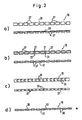
- the embodiment shown in FIG. 3a) corresponds essentially to the chain 19 according to FIG. 2.
- the individual chain links are formed by a multiplicity of cuboid steel blocks 27 which are arranged at a distance from one another and are connected to one another by a spring steel band 29.
- cuboid steel blocks 27 are used as chain links.
- the cuboid steel blocks 27 are connected to one another by two continuous steel cables 31, the spacing of the cuboid steel blocks 27 from one another being maintained by soldering points 33 being provided at the exit of the steel cables 31 from the blocks.
- the multi-link chain 19 is formed by a multiplicity of immediately adjacent solid chain links 35, two adjacent chain links 35 each being pivotable about a common axis 37 aligned in the assembled state parallel to the axis of the plug connection.
- the multi-link chain 19 consists of a plurality of interconnected steel rollers 39 arranged at a distance from one another.
- the steel rollers 39 like the cuboid steel blocks according to Fig. 3b), are held at a distance from one another by soldering points 33 attached to a steel cable 31 .
- a chain of this design is to be introduced into an annular space with a circular cross section formed between the male and female parts.
Landscapes
- Engineering & Computer Science (AREA)
- General Engineering & Computer Science (AREA)
- Mechanical Engineering (AREA)
- Life Sciences & Earth Sciences (AREA)
- Geology (AREA)
- Mining & Mineral Resources (AREA)
- Physics & Mathematics (AREA)
- Environmental & Geological Engineering (AREA)
- Fluid Mechanics (AREA)
- General Life Sciences & Earth Sciences (AREA)
- Geochemistry & Mineralogy (AREA)
- Earth Drilling (AREA)
Priority Applications (1)
| Application Number | Priority Date | Filing Date | Title |
|---|---|---|---|
| AT86105704T ATE62320T1 (de) | 1985-06-03 | 1986-04-25 | Steckverbindung fuer bohrgestaenge von erdbohrgeraeten. |
Applications Claiming Priority (2)
| Application Number | Priority Date | Filing Date | Title |
|---|---|---|---|
| DE3519773 | 1985-06-03 | ||
| DE19853519773 DE3519773A1 (de) | 1985-06-03 | 1985-06-03 | Steckverbindung fuer bohrgestaenge von erdbohrgeraeten |
Publications (3)
| Publication Number | Publication Date |
|---|---|
| EP0204128A2 EP0204128A2 (de) | 1986-12-10 |
| EP0204128A3 EP0204128A3 (en) | 1988-12-14 |
| EP0204128B1 true EP0204128B1 (de) | 1991-04-03 |
Family
ID=6272257
Family Applications (1)
| Application Number | Title | Priority Date | Filing Date |
|---|---|---|---|
| EP86105704A Expired - Lifetime EP0204128B1 (de) | 1985-06-03 | 1986-04-25 | Steckverbindung für Bohrgestänge von Erdbohrgeräten |
Country Status (5)
| Country | Link |
|---|---|
| US (1) | US4697947A (enExample) |
| EP (1) | EP0204128B1 (enExample) |
| JP (1) | JPS61277796A (enExample) |
| AT (1) | ATE62320T1 (enExample) |
| DE (2) | DE3519773A1 (enExample) |
Cited By (2)
| Publication number | Priority date | Publication date | Assignee | Title |
|---|---|---|---|---|
| WO2022173453A1 (en) * | 2021-02-12 | 2022-08-18 | Halliburton Energy Services, Inc. | Variable extension tube assembly with adjustable interlock device |
| EP4435226A3 (de) * | 2016-03-29 | 2024-12-18 | Herrenknecht Aktiengesellschaft | Bohrrohr sowie system und verfahren zum verlegen einer rohrleitung |
Families Citing this family (54)
| Publication number | Priority date | Publication date | Assignee | Title |
|---|---|---|---|---|
| DE3842081A1 (de) * | 1988-03-15 | 1989-09-28 | Hausherr & Soehne Rudolf | Bohrgeraet |
| FR2649181B1 (fr) * | 1989-06-29 | 1994-10-14 | Fmc Corp | Element de charge pour connecteur de tubes |
| JPH0672679B2 (ja) * | 1990-01-17 | 1994-09-14 | 八郎 井上 | 界面継手 |
| US5813705A (en) * | 1996-06-18 | 1998-09-29 | Victaulic Company Of America | Snap-action pipe coupling retainer |
| IT1288753B1 (it) * | 1996-10-14 | 1998-09-24 | Gevipi Ag | Dispositivo per il raccordo di un apparecchio idraulico ad un componente esterno. |
| DE19713446A1 (de) * | 1997-04-01 | 1998-10-08 | Bosch Gmbh Robert | Kupplung für Kraftstoffleitungen oder dergleichen |
| DE19749007C2 (de) * | 1997-11-06 | 1999-08-12 | Tracto Technik | Vorrichtung zum Verbinden eines Nachziehrohres mit einem Ziehgerät |
| CA2258339C (en) * | 1998-01-12 | 2005-04-05 | Prime Conduit, Inc. | Coupling assembly having enhanced axial tension strength and method of installation of coupled underground duct |
| US6343813B1 (en) * | 1999-04-30 | 2002-02-05 | Olson Irrigation Systems | Irrigation tubing connection system |
| DE10146186C1 (de) * | 2001-09-19 | 2003-03-06 | Rwe Rheinbraun Ag | Scherelement |
| US20030173775A1 (en) * | 2002-03-15 | 2003-09-18 | Mclanahan Corporation | Sand tank discharge elbow |
| US6739630B2 (en) | 2002-06-12 | 2004-05-25 | The Lamson & Sessions Co. | Pipe joint and coupling |
| US6739629B2 (en) | 2002-06-20 | 2004-05-25 | The Lamson & Sessions Co. | Bell and spigot joint with locking strap |
| CA2396666C (en) * | 2002-08-02 | 2005-03-01 | Bend All Automotive Incorporated | Press-formed keyway for headrest mounting tube |
| US6913293B1 (en) * | 2002-12-05 | 2005-07-05 | Pipelife Jet Stream Inc. | Spiral spline pipe joint apparatus and method |
| US6921114B1 (en) | 2002-12-20 | 2005-07-26 | Arnco Corporation | Coupler for conduits |
| US20040195834A1 (en) * | 2003-04-04 | 2004-10-07 | Steingass Robert W. | Fluid joint between fire equipment and connector |
| EP1482230A1 (fr) * | 2003-05-27 | 2004-12-01 | Hubert Antoine | Connecteur circulaire |
| DE102004016599B3 (de) * | 2004-04-03 | 2005-09-08 | Henn Gmbh & Co. Kg | Steckverbindung mit Winkelarretierung |
| EP1845299B1 (de) * | 2006-04-12 | 2009-03-04 | Ems-Chemie Ag | Anschlussvorrichtung für ein Rohr |
| PT1860275E (pt) * | 2006-04-26 | 2008-09-09 | Bauer Maschinen Gmbh | Dispositivo de acoplamento |
| PT1849956E (pt) * | 2006-04-26 | 2008-08-22 | Bauer Maschinen Gmbh | Acoplamento de tubagem para elementos tubulares |
| WO2008062443A2 (en) * | 2006-09-26 | 2008-05-29 | Jain Irrigation Systems Limited | A novel locking pipe joint and a method of making the same |
| WO2008042105A2 (en) * | 2006-09-28 | 2008-04-10 | Gandy Technologies Corporation | Push-together pipe assembly |
| US9714547B2 (en) * | 2008-12-29 | 2017-07-25 | Diamond Offshore Drilling, Inc. | Marine drilling riser connector with removable shear elements |
| DE102009053696A1 (de) * | 2009-11-18 | 2011-05-19 | Mahle International Gmbh | Anschlussvorrichtung |
| DE102009053695A1 (de) * | 2009-11-18 | 2011-05-19 | Mahle International Gmbh | Anschlussvorrichtung |
| CN102906482B (zh) * | 2010-06-04 | 2015-08-12 | 澳大利西亚钢铁产品私人有限公司 | 用于联接结构的剪元件及联接结构 |
| WO2012174571A2 (en) * | 2011-06-17 | 2012-12-20 | David L. Abney, Inc. | Subterranean tool with sealed electronic passage across multiple sections |
| CA2838278C (en) | 2011-06-20 | 2016-02-02 | David L. Abney, Inc. | Adjustable bent drilling tool having in situ drilling direction change capability |
| US8997849B2 (en) * | 2011-08-02 | 2015-04-07 | Plainsman Manufacturing Inc. | Isolated shearing mechanism for downhole tools |
| JP2012067599A (ja) * | 2012-01-10 | 2012-04-05 | Kubota Corp | 基礎杭の接続工法と基礎杭セットとキー部材 |
| US9169955B2 (en) * | 2012-07-17 | 2015-10-27 | Raytheon Company | Helical spline lock |
| ITTV20120182A1 (it) * | 2012-09-26 | 2014-03-27 | Renzo Porcellato | Giunto per aste o eliche di perforazione |
| US9200732B2 (en) | 2012-12-31 | 2015-12-01 | North American Specialty Products Llc | Flush joint pipe |
| US9458678B2 (en) * | 2013-02-15 | 2016-10-04 | Unmanned Ad-Hoc Industries, Inc. | Threadless torque connector |
| US9951895B2 (en) * | 2013-03-11 | 2018-04-24 | United Technologies Corporation | Two-piece self-locking mechanism for tube assemblies |
| ITRM20130533A1 (it) * | 2013-10-02 | 2015-04-03 | Mori Srl | Giunto tra testa motrice "rotary" e testa dell'asta di perforazione superiore, in un impianto di perforazione del suolo ed eventuale dispositivo per l'aggancio/sgancio meccanizzato. |
| CN104433014B (zh) * | 2014-08-28 | 2016-10-12 | 吴柏熙 | 一种首饰链锁扣 |
| GB201501440D0 (en) * | 2015-01-28 | 2015-03-11 | Acorn Intellectual Properties Ltd | Connectors for sleeved pipe couplings |
| US9695876B2 (en) * | 2015-07-29 | 2017-07-04 | Hamilton Sundstrand Corporation | Bearing retention method and apparatus |
| US10058805B2 (en) * | 2015-10-30 | 2018-08-28 | Caterpillar Inc. | Ripcord locking methods |
| CN108700239B (zh) * | 2016-02-10 | 2020-12-15 | 埃姆斯·帕特恩特股份有限公司 | 连接设备 |
| CN107655368A (zh) * | 2017-10-27 | 2018-02-02 | 西安工业大学 | 一种非接触式空气炮测速设备及其方法 |
| EP3480419B1 (de) * | 2017-11-02 | 2020-04-08 | BAUER Spezialtiefbau GmbH | Schneckenbohreranordnung und verfahren zum bilden einer schneckenbohreranordnung |
| DE102017127845A1 (de) | 2017-11-24 | 2019-05-29 | Minimax Gmbh & Co. Kg | Steckverbindersystem für fluidleitende Bauteile, insbesondere von Feuerlöschsystemen, sowie dessen Bestandteile |
| CN108661571A (zh) * | 2018-04-26 | 2018-10-16 | 上海金泰工程机械有限公司 | 用于伸缩钻杆续接的柔性锁链结构及其使用方法 |
| GB2573143B (en) * | 2018-04-26 | 2022-05-25 | Morphpackers Ltd | Improvements in or relating to coupling of tubulars downhole |
| WO2020132122A1 (en) * | 2018-12-18 | 2020-06-25 | Marcilese Joseph P | A piping connection system |
| US11111737B2 (en) | 2019-10-01 | 2021-09-07 | Morphpackers Limited | Downhole coupling mechanism |
| US11839440B2 (en) | 2021-07-30 | 2023-12-12 | Corindus, Inc. | Attachment for robotic medical system |
| US11905774B2 (en) | 2021-11-23 | 2024-02-20 | Vertice Oil Tools Inc. | Anchor mechanism |
| WO2023094483A2 (en) | 2021-11-23 | 2023-06-01 | Vertice Oil Tools Inc. | Anchor mechanism |
| CN114776265A (zh) * | 2022-03-29 | 2022-07-22 | 中煤科工集团西安研究院有限公司 | 一种筛管柔性插接装置和方法 |
Family Cites Families (10)
| Publication number | Priority date | Publication date | Assignee | Title |
|---|---|---|---|---|
| FR1310712A (fr) * | 1961-10-20 | 1962-11-30 | Nord Aviation | Perfectionnements aux procédés et dispositifs d'assemblage de corps tubulaires ou d'enveloppes cylindriques |
| NL294109A (enExample) * | 1962-06-15 | |||
| DE1206378B (de) * | 1964-08-04 | 1965-12-09 | Bergbaumaschinen Seehausen Veb | Schnellverbindung fuer Grossbohrrohre, insbesondere fuer Tiefbohrungen |
| DE2357260A1 (de) * | 1973-11-16 | 1975-05-22 | Wanit Ges F Asbestzement Erzeu | Verbindungselement fuer eine schubgesicherte rohrverbindung |
| US3910566A (en) * | 1974-05-15 | 1975-10-07 | Case Co J I | Coil spring detent assembly |
| US4052091A (en) * | 1975-02-10 | 1977-10-04 | T K Valve & Manufacturing, Inc. | Coupling device |
| SU570755A1 (ru) * | 1975-03-19 | 1977-08-30 | Всесоюзный Научно-Исследовательский Институт Разработки И Эксплуатации Труб Нефтянного Сортамента | Быстроразъемное соединение труб |
| FI753090A7 (enExample) * | 1975-11-05 | 1977-05-06 | Goeran Sundholm | |
| US4293148A (en) * | 1979-02-22 | 1981-10-06 | Fmc Corporation | Pile connector |
| SE8103203L (sv) * | 1981-05-21 | 1982-11-22 | Volvo Penta Ab | Anordning for lasning av en rotationsdel |
-
1985
- 1985-06-03 DE DE19853519773 patent/DE3519773A1/de not_active Withdrawn
-
1986
- 1986-04-25 DE DE8686105704T patent/DE3678491D1/de not_active Expired - Fee Related
- 1986-04-25 EP EP86105704A patent/EP0204128B1/de not_active Expired - Lifetime
- 1986-04-25 AT AT86105704T patent/ATE62320T1/de not_active IP Right Cessation
- 1986-05-29 US US06/868,006 patent/US4697947A/en not_active Expired - Fee Related
- 1986-05-29 JP JP61125612A patent/JPS61277796A/ja active Granted
Cited By (4)
| Publication number | Priority date | Publication date | Assignee | Title |
|---|---|---|---|---|
| EP4435226A3 (de) * | 2016-03-29 | 2024-12-18 | Herrenknecht Aktiengesellschaft | Bohrrohr sowie system und verfahren zum verlegen einer rohrleitung |
| WO2022173453A1 (en) * | 2021-02-12 | 2022-08-18 | Halliburton Energy Services, Inc. | Variable extension tube assembly with adjustable interlock device |
| GB2615933A (en) * | 2021-02-12 | 2023-08-23 | Halliburton Energy Services Inc | Variable extension tube assembly with adjustable interlock device |
| GB2615933B (en) * | 2021-02-12 | 2025-02-19 | Halliburton Energy Services Inc | Variable extension tube assembly with adjustable interlock device |
Also Published As
| Publication number | Publication date |
|---|---|
| US4697947A (en) | 1987-10-06 |
| EP0204128A2 (de) | 1986-12-10 |
| JPH033038B2 (enExample) | 1991-01-17 |
| ATE62320T1 (de) | 1991-04-15 |
| JPS61277796A (ja) | 1986-12-08 |
| EP0204128A3 (en) | 1988-12-14 |
| DE3678491D1 (de) | 1991-05-08 |
| DE3519773A1 (de) | 1986-12-04 |
Similar Documents
| Publication | Publication Date | Title |
|---|---|---|
| EP0204128B1 (de) | Steckverbindung für Bohrgestänge von Erdbohrgeräten | |
| EP0353182B1 (de) | Rohrgewindeverbindung | |
| DE69001524T2 (de) | Rohrleitungsverbindung. | |
| DE2760197C2 (de) | Rohrverbindung, insbesondere für Bohrfeldrohre | |
| DE3121899C2 (enExample) | ||
| DE602004009812T2 (de) | Verriegelungsvorrichtung für hergestellte rohrverbindungen | |
| DE4334529C2 (de) | Verbindungsvorrichtung für ein flexibles Wellrohr | |
| DE69412779T2 (de) | Endrohr-kupplung mit in umfangsrichtung bewegbaren klemmbacken | |
| EP0314123A2 (de) | Kupplung, insbesondere für Diamantbohrkrone mit Schaftrohr und Rohrgewindeanschluss | |
| DE3883428T2 (de) | Rohrförmige Kupplung. | |
| EP0235581A1 (de) | Kupplung, insbesondere für Diamantbohrkrone mit Schaftrohr und Rohrgewindeanschluss | |
| DE4000231A1 (de) | Wellenkupplung | |
| CH663832A5 (de) | Rohrschelle zum verbinden zweier rohrenden. | |
| DE4090435C1 (enExample) | ||
| DE3207180C1 (de) | Rohrverbindung für Metallrohre | |
| DE3126405A1 (de) | Steckkupplung, insbesondere fuer hydraulische hochdruck- und hoechstdruckleitungen | |
| DE2558650A1 (de) | Selbstabsperrende schnellkupplung fuer gas- oder fluessigkeitsfuehrende leitungen | |
| DE4211081C1 (en) | Multiple drill pipe - allows limited inner pipe projection to facilitate coupling to other drill pipes | |
| EP0458289B1 (de) | Verbindung für Bohrrohre od.dgl. | |
| DE2551254A1 (de) | Rohrverbindungsstueck | |
| DE102006056663B4 (de) | Gewindeverbindung für Bohrgestänge | |
| EP0780583B1 (de) | Kupplung für die Verbindung von stabförmigen Teilen | |
| EP3480419A1 (de) | Schneckenbohreranordnung und verfahren zum bilden einer schneckenbohreranordnung | |
| DE3207183C1 (de) | Rohrverbindung für Metallrohre | |
| DE3524865C2 (enExample) |
Legal Events
| Date | Code | Title | Description |
|---|---|---|---|
| PUAI | Public reference made under article 153(3) epc to a published international application that has entered the european phase |
Free format text: ORIGINAL CODE: 0009012 |
|
| AK | Designated contracting states |
Kind code of ref document: A2 Designated state(s): AT BE CH DE FR GB IT LI LU NL SE |
|
| RAP1 | Party data changed (applicant data changed or rights of an application transferred) |
Owner name: BAUER SPEZIALTIEFBAU GMBH |
|
| PUAL | Search report despatched |
Free format text: ORIGINAL CODE: 0009013 |
|
| AK | Designated contracting states |
Kind code of ref document: A3 Designated state(s): AT BE CH DE FR GB IT LI LU NL SE |
|
| 17P | Request for examination filed |
Effective date: 19890117 |
|
| 17Q | First examination report despatched |
Effective date: 19890901 |
|
| GRAA | (expected) grant |
Free format text: ORIGINAL CODE: 0009210 |
|
| AK | Designated contracting states |
Kind code of ref document: B1 Designated state(s): AT BE CH DE FR GB IT LI LU NL SE |
|
| PG25 | Lapsed in a contracting state [announced via postgrant information from national office to epo] |
Ref country code: IT Free format text: LAPSE BECAUSE OF FAILURE TO SUBMIT A TRANSLATION OF THE DESCRIPTION OR TO PAY THE FEE WITHIN THE PRESCRIBED TIME-LIMIT;WARNING: LAPSES OF ITALIAN PATENTS WITH EFFECTIVE DATE BEFORE 2007 MAY HAVE OCCURRED AT ANY TIME BEFORE 2007. THE CORRECT EFFECTIVE DATE MAY BE DIFFERENT FROM THE ONE RECORDED. Effective date: 19910403 Ref country code: BE Effective date: 19910403 Ref country code: FR Effective date: 19910403 Ref country code: GB Effective date: 19910403 Ref country code: NL Effective date: 19910403 Ref country code: SE Effective date: 19910403 |
|
| REF | Corresponds to: |
Ref document number: 62320 Country of ref document: AT Date of ref document: 19910415 Kind code of ref document: T |
|
| PG25 | Lapsed in a contracting state [announced via postgrant information from national office to epo] |
Ref country code: LU Free format text: LAPSE BECAUSE OF NON-PAYMENT OF DUE FEES Effective date: 19910430 |
|
| REF | Corresponds to: |
Ref document number: 3678491 Country of ref document: DE Date of ref document: 19910508 |
|
| EN | Fr: translation not filed | ||
| NLV1 | Nl: lapsed or annulled due to failure to fulfill the requirements of art. 29p and 29m of the patents act | ||
| GBV | Gb: ep patent (uk) treated as always having been void in accordance with gb section 77(7)/1977 [no translation filed] | ||
| PLBE | No opposition filed within time limit |
Free format text: ORIGINAL CODE: 0009261 |
|
| STAA | Information on the status of an ep patent application or granted ep patent |
Free format text: STATUS: NO OPPOSITION FILED WITHIN TIME LIMIT |
|
| 26N | No opposition filed | ||
| PGFP | Annual fee paid to national office [announced via postgrant information from national office to epo] |
Ref country code: AT Payment date: 19950322 Year of fee payment: 10 |
|
| PGFP | Annual fee paid to national office [announced via postgrant information from national office to epo] |
Ref country code: CH Payment date: 19950411 Year of fee payment: 10 |
|
| PGFP | Annual fee paid to national office [announced via postgrant information from national office to epo] |
Ref country code: DE Payment date: 19950427 Year of fee payment: 10 |
|
| PG25 | Lapsed in a contracting state [announced via postgrant information from national office to epo] |
Ref country code: AT Effective date: 19960425 |
|
| PG25 | Lapsed in a contracting state [announced via postgrant information from national office to epo] |
Ref country code: CH Effective date: 19960430 Ref country code: LI Effective date: 19960430 |
|
| REG | Reference to a national code |
Ref country code: CH Ref legal event code: PL |
|
| PG25 | Lapsed in a contracting state [announced via postgrant information from national office to epo] |
Ref country code: DE Effective date: 19970101 |