EP0203620B1 - Steuerorgan eines Eintreibwerkzeugs für Befestigungsmittel - Google Patents
Steuerorgan eines Eintreibwerkzeugs für Befestigungsmittel Download PDFInfo
- Publication number
- EP0203620B1 EP0203620B1 EP86107489A EP86107489A EP0203620B1 EP 0203620 B1 EP0203620 B1 EP 0203620B1 EP 86107489 A EP86107489 A EP 86107489A EP 86107489 A EP86107489 A EP 86107489A EP 0203620 B1 EP0203620 B1 EP 0203620B1
- Authority
- EP
- European Patent Office
- Prior art keywords
- trigger
- tool
- lever
- activator
- fastener driving
- Prior art date
- Legal status (The legal status is an assumption and is not a legal conclusion. Google has not performed a legal analysis and makes no representation as to the accuracy of the status listed.)
- Expired
Links
- 230000007246 mechanism Effects 0.000 claims description 82
- 239000012190 activator Substances 0.000 claims description 30
- 238000010304 firing Methods 0.000 claims description 22
- 230000001276 controlling effect Effects 0.000 claims description 3
- 230000001105 regulatory effect Effects 0.000 claims description 2
- 239000012530 fluid Substances 0.000 claims 1
- 230000000717 retained effect Effects 0.000 description 4
- 230000000994 depressogenic effect Effects 0.000 description 3
- 230000000694 effects Effects 0.000 description 2
- 230000009471 action Effects 0.000 description 1
- 230000008859 change Effects 0.000 description 1
- ZPUCINDJVBIVPJ-LJISPDSOSA-N cocaine Chemical compound O([C@H]1C[C@@H]2CC[C@@H](N2C)[C@H]1C(=O)OC)C(=O)C1=CC=CC=C1 ZPUCINDJVBIVPJ-LJISPDSOSA-N 0.000 description 1
- 230000006835 compression Effects 0.000 description 1
- 238000007906 compression Methods 0.000 description 1
- 238000010276 construction Methods 0.000 description 1
- 230000007812 deficiency Effects 0.000 description 1
- 230000003993 interaction Effects 0.000 description 1
- 238000000034 method Methods 0.000 description 1
Images

Classifications
-
- B—PERFORMING OPERATIONS; TRANSPORTING
- B25—HAND TOOLS; PORTABLE POWER-DRIVEN TOOLS; MANIPULATORS
- B25C—HAND-HELD NAILING OR STAPLING TOOLS; MANUALLY OPERATED PORTABLE STAPLING TOOLS
- B25C1/00—Hand-held nailing tools; Nail feeding devices
- B25C1/008—Safety devices
Definitions
- This invention relates to a portable fastener driving tool and, particularly, to a novel actuating means which prevents actuation of the tool under certain conditions.
- the work contacting mechanism includes a portion disposed adjacent the trigger assembly, and the trigger assembly is designed so that movement of the trigger is either (1) totally prevented until the bottom trigger mechanism engages a workpiece, or (2) sufficient movement of the trigger to effectuate actuation of the tool will not take place to operate a valve mechanism controlling the operation of the tool until the bottom trip mechanism is in engagement with the workpiece.
- the usual bottom trip mechanism employed in a fastener driving tool, while working in conjunction with the trigger does not normally require any particular sequence of operation between the trigger assembly and the bottom trip mechanism. It is usually necessary that both the bottom trip be engaged and the trigger pulled before the tool will be fired, but this can be done in any sequence.
- the actuating means for the tool be designed so that only a single fastener can be fired from the tool by following the prescribed sequence of first contacting the workpiece and then pulling the trigger, and that subsequent fasteners can only be singly fired if the operator were to release the trigger after each firing. This would prevent the inadvertent firing of a subsequent fastener unless and until the operator were to release the trigger, and the sequence again followed calling for the first step to be engagement of the tool with a workpiece.
- DE-A 2 311 147 discloses an actuating device which prevents the firing thereof until the bottom trip mechanism has been actuated. This concept is generally known, and while it works in the afore-mentioned manner, it would not prevent firing of the tool by engagement of the bottom trip mechanism when the trigger is held in the operating position.
- a novel actuating mechanism which insures that the prescribed sequential mode of firing takes place calling for first actuating the bottom trip mechanism and then pulling the trigger before a fastener is fired. If the trigger is initially pulled and then the bottom trip mechanism is actuated, the trigger mechanism will be effectively locked out of position, thus preventing the tool from being fired.
- further mechanisms are provided which enable the tool to be placed in a "bottom trip mode,” where the tool will be fired by engagement of the tool with a workpiece, with the trigger maintained in a "pulled” position.
- the tool will be operated to fire a fastener each time the bottom trip mechanism engages with the workpiece.
- the actuating mechanism automatically goes back into its sequential mode, which means that for a subsequent fastener to be driven, the bottom trip mechanism will first have to be actuated and then the trigger pulled to activate the tool.
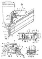
- FIG. 1 there is shown a portable pneumatic fastener driving tool generally indicated at 2 embodying the novel actuating mechanism.
- the tool 2 shown is of a conventional, pneumatically operated fastener driving device which includes a housing 4 within which is located a driving piston slidable within a cylinder and having a driving member (not shown) secured thereto, which extends through the nose portion 5 of the housing 4 to engage and drive a fastener therethrough and into a workpiece.
- the flow of high-pressure air from the pressure chamber 8 to actuate the driving piston is regulated by a valve mechanism 10, which in turn is controlled by applicant's novel trigger assembly 12.
- the pneumatic fastener driving tool shown is merely representative of one that can be employed, and details of the valve mechanism controlling the flow of air to the driving piston, the piston, etc., can be seen by referring to Howard et al. patent 3,815,475, which is assigned to the assignee of the present invention.
- a bottom trip mechanism 14 that is disposed alongside the nose portion 5 of the fastener driving tool though which the fastener is exited by operation of the driving piston and attached driving member.
- the fasteners (not shown) are directed into the nose portion 5 from a conventional magazine 6 secured to the housing 4.
- the bottom trip mechanism 14 includes a bracket assembly 18 which includes an upper plate section 19 leading to the trigger assembly 12. Secured to the bracket 18 at its lower end is an actuator 20 which extends through a guide 21 disposed adjacent the nose portion 5. The bottom trip mechanism is maintained in the position shown in FIG. 1, where it extends outwardly beyond the nose portion 5 by compression spring 22 disposed between the upper portion of the bracket assembly 18 and housing 4.
- the upper plate section 19 of the bracket 18 includes an upper lip portion 24 which coacts with the novel trigger assembly which will be discussed hereinafter.
- Pin 26 secured to housing 4 limits the downward movement of bracket 18.
- FIG. 3 there is shown the trigger assembly 12 in the relaxed position. That is to say, the U-shaped trigger 30, which is pivotally mounted about pin 32, is spaced from valve pin 34 which controls the movement of the valve 10 to effect firing of the tool by bringing about the introduction of high-pressure air to operate the driving piston in the driving stroke.
- Pin 34 is normally spring-biased outwardly to the position shown in FIG. 3 by spring 11 (see FIG. 1).
- the trigger assembly includes a lever member 36 that is pivotally connected to the U-shaped trigger member 30 at one end thereof. It is this member 36 that functions to contact and move the valve pin 34 to control the firing of the tool.
- the lever is resiliently spaced from the base of the trigger member 30 into the position shown in FIG. 3 by the button 42 disposed in hole 41, which button 42 is spring-biased outwardly by the spring 44. Spring 44 is retained in place by cap 45.
- the position of the lever 36 and the movement of the trigger assembly 12 will determine the firing mode of the toot. Accordingly, if firing of the tool requires a predetermined movement of the lever 36 when in engagement with the valve pin 34, this travel is occasioned by pivoting of the trigger 30 and operation of the bottom trip mechanism now to be described.
- the interaction between the bottom trip mechanism 14 and the trigger assembly takes place through an L-shaped activator member 27 that is pivotally mounted to the trigger 30 by pin 28, which is located adjacent pivot pin 32 (see FIG. 3). With the tool spaced from the workpiece, the bottom trip mechanism 14 is in the position shown in FIGS. 1 and 3, with the lip 24 of the upper plate section 19 being out of engagement with the activator 27.
- valve pin 34 is engaged by the lever 36 to move it a prescribed amount to effect movement of the valve 10 to fire the tool. This is accomplished by initial movement of the bottom trip mechanism 14 which moves the lip 24 upwardly into engagement with the activator 27 to rotate it in a clockwise position to place it in the general position shown in FIG. 5. Essentially, movement of the lip 24 moves the activator 27 against the underside of lever 36 to move lever 36 against valve pin 34. Then pivoting of the trigger 30 about pin 32 moves lever 36 about activator 27 to depress valve pin 34 to fire the tool (FIG. 5).
- the actuating means will find itself in the position shown in FIG. 6. That is to say, lever member 36 will have been moved into the position shown in FIG. 5 by counterclockwise movement of the trigger member 30 about the pivot pin 32, which movement will place the lever member adjacent the valve pin 34, but will not activate the valve mechanism 10. Subsequent movement of the bottom trip mechanism will move the lip 24 against the activator 27 to move the activator in a clockwise position to that shown in FIG. 5, wherein the lever 36 will be located in the slot 29 of the activator 27.
- slot 29 has a width substantially equal to that of lever 36, but is less than that of the width of activator 27 for reasons to be described hereinafter.
- the activator 27 will not act to move the lever 36 to move the valve pin 34 to fire the tool as previously discussed when the proper firing mode is followed.
- the tool cannot be fired unless the prescribed sequence is followed. That is, initially the bottom trip must be actuated before the trigger is pulled. In this way, if the operator were to carry the tool with the trigger depressed the tool will not fire, regardless of what happens to the bottom trip mechanism.
- the tool be capable of being fired by mere actuation of the bottom trip mechanism when the trigger is held in the depressed condition.
- this is accomplished by a novel arrangement which must be manually activated by the operator, and which will only be effective when the trigger is continuously retained in its actuating condition. That is to say that the operator must manually and continuously activate a mechanism that will enable the tool to be continuously fired by engagement of the bottom trip mechanism as long as the trigger is being retained in the pulled condition.
- the sequential mode must again be followed before a fastener will be fired. That is to say, the bottom trip mechanism must be first activated, after which the trigger can be pulled to drive a fastener.
- the trigger assembly 12 is provided to retain the lever 36 in the position shown in FIG. 10 when the trigger 30 is pulled and held. That is, the lever must be so positioned that after the trigger is pulled and held, movement of the activator 27 by the bottom trip mechanism 14 will move lever 36 in engagement with valve pin 34 the prescribed distance to fire the tool.
- FIG. 4 illustrates a cross-sectional view of a reset button arrangement forming part of the trigger assembly provided for this purpose. It consists of a button 38 which is located in an opening in a sidewall of the U-shaped trigger member 30, which button 38 includes a sleeve portion 39 that is slidably disposed on a guide rod 48 (which rod also serves as the pivot pin for the lever 36) located in an opposite sidewall.
- the button is biased outwardly by spring 40.
- the lever 36 is also provided with the spring-biased push button 42, as described hereinbefore.
- the springloaded button 42 rests on a raised surface 46 of the trigger member 30.
- the spring forces exerted by the springs 11, 40 and 44 are designed to maintain the valve pin 34, button 42, and button 38, respectively, in the positions shown in FIGS. 1-4.
- the spring force exerted by the spring 11 of the valve 10 is sufficiently large that after the bottom trip is released the pin 34 will force the lever 34 downwardly against the action of the spring 44. If the bottom trip is reactuated, with the trigger held, the activator is moved to the position shown in FIG. 6, where it rides over the lever 36, which falls into slot 29, thus preventing firing of the tool.
- the button 38 is pushed inwardly to move lever 36 to the position shown in FIGS. 7 and 8. This can be done before or after the trigger has been pulled. When this occurs, the lever 36 is moved to the position shown in FIG. 8, with the button 42 riding off of the surface 46. As particularly shown in FIG. 7, the lever 36 is now not disposed immediately above the slot 29 formed in activator 27, as shown in FIG. 2.
- the actuating mechanism finds itself in the position shown in FIG. 10, wherein the bottom trip mechanism has not been activated.
- the activator 27 will force the lever 36 upwardly against the valve pin 34 to fire the tool.
- the firing mode is seen in FIG. 9.
- the lever 36 is now not directly above the slot 29, if the trigger remains in the pulled position, which is that shown in FIG. 10, release of the bottom trip mechanism would not result in the lever moving into the slot 29, as shown in FIG. 6.
- the tool will be fired each time the bottom trip mechanism is activated.
Landscapes
- Engineering & Computer Science (AREA)
- Mechanical Engineering (AREA)
- Portable Nailing Machines And Staplers (AREA)
Claims (10)
Applications Claiming Priority (2)
| Application Number | Priority Date | Filing Date | Title |
|---|---|---|---|
| US06/737,780 US4629106A (en) | 1985-05-29 | 1985-05-29 | Actuating means for fastener driving tool |
| US737780 | 1985-05-29 |
Publications (2)
| Publication Number | Publication Date |
|---|---|
| EP0203620A1 EP0203620A1 (de) | 1986-12-03 |
| EP0203620B1 true EP0203620B1 (de) | 1990-06-13 |
Family
ID=24965286
Family Applications (1)
| Application Number | Title | Priority Date | Filing Date |
|---|---|---|---|
| EP86107489A Expired EP0203620B1 (de) | 1985-05-29 | 1986-05-28 | Steuerorgan eines Eintreibwerkzeugs für Befestigungsmittel |
Country Status (4)
| Country | Link |
|---|---|
| US (1) | US4629106A (de) |
| EP (1) | EP0203620B1 (de) |
| CA (1) | CA1268001A (de) |
| DE (1) | DE3671855D1 (de) |
Families Citing this family (63)
| Publication number | Priority date | Publication date | Assignee | Title |
|---|---|---|---|---|
| DE3703753A1 (de) * | 1987-02-07 | 1988-08-18 | Haubold Kihlberg Gmbh | Eintreibgeraet fuer befestigungsmittel mit einer ausloesesicherheitseinrichtung |
| US4811882A (en) * | 1987-10-26 | 1989-03-14 | Sencorp | Restrictive trigger actuated valve arrangement for a fastener driving tool |
| DE8810753U1 (de) * | 1988-08-25 | 1988-10-20 | Joh. Friedrich Behrens AG, 2070 Ahrensburg | Eintreibgerät für Befestigungsmittel |
| DE8914926U1 (de) * | 1989-12-19 | 1990-02-01 | Joh. Friedrich Behrens AG, 2070 Ahrensburg | Auslösegesichertes Eintreibgerät für Befestigungsmittel |
| US5080273A (en) * | 1989-12-19 | 1992-01-14 | Duo-Fast Corporation | Trigger valve and safety mechanism for fastener driving tool |
| DE4032231A1 (de) * | 1989-12-19 | 1991-06-20 | Behrens Ag Friedrich Joh | Ausloesegesichertes eintreibgeraet fuer befestigungsmittel |
| US5174485A (en) * | 1989-12-19 | 1992-12-29 | Duo-Fast Corporation | Fastener driving tool |
| AU7704691A (en) * | 1990-05-15 | 1991-11-21 | Duo-Fast Corp. | Safety interlock system for fastener driving tool |
| USD334329S (en) | 1990-09-21 | 1993-03-30 | Hitachi Koki Company, Limited | Portable pneumatic nailer |
| US5083694A (en) * | 1991-06-11 | 1992-01-28 | Stanley-Bostitch, Inc. | Fastener driving device with sequential actuation trigger assembly |
| US5366132A (en) * | 1993-04-14 | 1994-11-22 | Stanley-Bostitch, Inc. | Portable fastener driving device with inadvertent impact activation prevention |
| DE9305760U1 (de) * | 1993-04-16 | 1993-06-17 | Joh. Friedrich Behrens AG, 2070 Ahrensburg | Auslösesicherung an einem Eintreibgerät für Befestigungsmittel |
| JP2727960B2 (ja) * | 1994-02-28 | 1998-03-18 | マックス株式会社 | 釘打機の起動装置 |
| US5551620A (en) * | 1994-08-10 | 1996-09-03 | Stanley-Bostitch, Inc. | Convertible contact/sequential trip trigger |
| IT1281548B1 (it) * | 1995-04-19 | 1998-02-18 | Fasco Spa | Meccanismo di scatto con dispositivo di sicurezza per fissatrice ad aria compressa |
| DE29508658U1 (de) * | 1995-05-24 | 1995-07-27 | Joh. Friedrich Behrens AG, 22926 Ahrensburg | Eintreibgerät für Befestigungsmittel |
| US5687897A (en) * | 1995-07-28 | 1997-11-18 | Campbell Hausfeld/Scott Fetzer Company | Dual mode pneumatic tool |
| US5709333A (en) * | 1996-11-25 | 1998-01-20 | Regitar Power Tools Co., Ltd. | Safety device for a stapling gun |
| DE19722512C1 (de) * | 1997-05-30 | 1998-11-19 | Behrens Ag Friedrich Joh | Eintreibgerät für Befestigungsmittel |
| US5836501A (en) * | 1997-06-23 | 1998-11-17 | Basso Industry Corp. | Safety trigger mechanism for stapler |
| US5862969A (en) * | 1997-09-17 | 1999-01-26 | De Poan Pneumatic Corporation | Safety trigger for nailer |
| US5909836A (en) * | 1997-10-31 | 1999-06-08 | Illinois Tool Works Inc. | Combustion powered tool with combustion chamber lockout |
| US6145724A (en) * | 1997-10-31 | 2000-11-14 | Illinois Tool Works, Inc. | Combustion powered tool with combustion chamber delay |
| US6371348B1 (en) | 1999-08-06 | 2002-04-16 | Stanley Fastening Systems, Lp | Fastener driving device with enhanced sequential actuation |
| JP3780822B2 (ja) * | 2000-05-23 | 2006-05-31 | 日立工機株式会社 | 釘打機 |
| USRE42987E1 (en) * | 2000-05-23 | 2011-12-06 | Hitachi Koki Co., Ltd. | Nail gun with safety portion mechanism for preventing misfires |
| US6604664B2 (en) * | 2001-01-16 | 2003-08-12 | Illinois Tool Works Inc. | Safe trigger with time delay for pneumatic fastener driving tools |
| US6648202B2 (en) | 2001-02-08 | 2003-11-18 | Black & Decker Inc. | Pneumatic fastening tool |
| US6715655B1 (en) * | 2003-01-03 | 2004-04-06 | Illinois Tool Works Inc. | Combustion chamber lock-out mechanism |
| JP4135574B2 (ja) * | 2003-06-20 | 2008-08-20 | 日立工機株式会社 | 釘打機 |
| JP4103724B2 (ja) * | 2003-08-11 | 2008-06-18 | マックス株式会社 | ステープラにおける紙押えテーブルのロック機構 |
| JP4102998B2 (ja) * | 2003-09-10 | 2008-06-18 | マックス株式会社 | 釘打機の起動装置 |
| US20050127127A1 (en) * | 2003-12-16 | 2005-06-16 | Wen-Sheng Huang | Safety switch of screwdriver |
| TW200600288A (en) * | 2004-02-20 | 2006-01-01 | Black & Decker Inc | Adjustable exhaust system for pneumatic nailers and staplers |
| US7073697B2 (en) * | 2004-08-12 | 2006-07-11 | Chien-Chuan Lin | Trigger switch structure of nail driver |
| US7191927B2 (en) * | 2005-06-13 | 2007-03-20 | Illinois Tool Works Inc. | Fastener-driving tool having trigger control mechanism for alternatively permitting bump firing and sequential firing modes of operation |
| US20070125822A1 (en) * | 2005-12-07 | 2007-06-07 | Liu Chung-Ho | Firing mechanism of a nailing machine |
| CN100448620C (zh) * | 2005-12-29 | 2009-01-07 | 纬和有限公司 | 具保险装置的打钉枪 |
| CN100445042C (zh) * | 2005-12-29 | 2008-12-24 | 纬和有限公司 | 具安全保护装置的射钉枪 |
| US7540400B2 (en) | 2006-01-06 | 2009-06-02 | Staples The Office Superstore, Llc | Stapler having a moveable strike plate with lockout mechanism |
| US7395955B2 (en) | 2006-01-06 | 2008-07-08 | Staples The Office Superstore, Llc | Stapler |
| TW200732100A (en) * | 2006-02-20 | 2007-09-01 | Samson Power Tool Co Ltd | Safety structure of nail gun |
| JP4720551B2 (ja) * | 2006-03-08 | 2011-07-13 | 日立工機株式会社 | 燃焼式動力工具 |
| US20070278275A1 (en) * | 2006-06-05 | 2007-12-06 | Basso Industry Corp. | Trigger switching mechanism of a nailing machine |
| US7786397B2 (en) * | 2006-09-20 | 2010-08-31 | Makita U.S.A., Inc. | Safety trigger guard |
| US7213733B1 (en) * | 2006-12-20 | 2007-05-08 | De Poan Pneumatic Corp. | Nail gun switch mechanism for switching dual actuation modes |
| TW200838653A (en) * | 2007-03-28 | 2008-10-01 | Mao-Xuan Shao | Safety structure for nail gun |
| JP4507211B2 (ja) * | 2007-09-03 | 2010-07-21 | 日立工機株式会社 | 打込機 |
| US20090108046A1 (en) * | 2007-10-24 | 2009-04-30 | Chi-Sheng Huang | Trigger Switch Mechanism for Nail Gun |
| US7810688B2 (en) * | 2007-12-21 | 2010-10-12 | De Poan Pneumatic Corp. | Nail gun switch mechanism |
| US7784560B2 (en) | 2008-03-31 | 2010-08-31 | Illinois Tool Works Inc. | Cap assembly of a fastener-driving tool having switch mechanism incorporated therein for switching modes of operation of the fastener-driving tool |
| TW200942375A (en) * | 2008-04-07 | 2009-10-16 | Basso Ind Corp | Nail gun with safety device |
| TW200948553A (en) * | 2008-05-16 | 2009-12-01 | Apach Ind Co Ltd | Switching device for single discharge and continuous discharge of nail gun |
| US8800835B2 (en) | 2008-07-17 | 2014-08-12 | Stanley Fastening Systems, Lp | Fastener driving device with mode selector and trigger interlock |
| US7975890B2 (en) * | 2008-08-26 | 2011-07-12 | Jhih-Siang Tang | Switching mechanism for stapling modes of a stapler |
| US7922054B2 (en) * | 2008-09-23 | 2011-04-12 | Robert Bosch Gmbh | Nail gun with integrated safety device |
| TWM394212U (en) * | 2010-08-04 | 2010-12-11 | Central Fastener Co Ltd | Trigger switching device of nailer |
| JP5447285B2 (ja) * | 2010-08-12 | 2014-03-19 | マックス株式会社 | ガス燃焼式打ち込み工具 |
| US8833626B2 (en) | 2010-09-29 | 2014-09-16 | Stanley Fastening Systems, L.P. | Fastening tool |
| USD756739S1 (en) | 2014-06-02 | 2016-05-24 | Stanley Fastening Systems, L.P. | Pneumatic nailer |
| USD756740S1 (en) | 2014-06-02 | 2016-05-24 | Stanley Fastening Systems, L.P. | Pneumatic nailer |
| TWI753088B (zh) * | 2018-01-17 | 2022-01-21 | 鑽全實業股份有限公司 | 打釘槍及其擊發切換裝置 |
| IT201900012336A1 (it) * | 2019-07-19 | 2021-01-19 | Omer S P A | “pistola chiodatrice pneumatica a sparo sequenziale dotato di dispositivo di sicurezza” |
Family Cites Families (3)
| Publication number | Priority date | Publication date | Assignee | Title |
|---|---|---|---|---|
| US4523646A (en) * | 1980-06-02 | 1985-06-18 | Duo-Fast Corporation | Fastener driving tool |
| DE3142237A1 (de) * | 1981-10-24 | 1983-05-05 | Signode Corp., Glenview, Ill. | Pneumatisch betaetigbares befestigungsmitteleintreibgeraet |
| EP0086244B1 (de) * | 1982-02-13 | 1985-01-16 | Joh. Friedrich Behrens AG | Auslösesicherung für ein kraftgetriebenes Eintreibgerät |
-
1985
- 1985-05-29 US US06/737,780 patent/US4629106A/en not_active Expired - Lifetime
-
1986
- 1986-05-15 CA CA000509229A patent/CA1268001A/en not_active Expired
- 1986-05-28 EP EP86107489A patent/EP0203620B1/de not_active Expired
- 1986-05-28 DE DE8686107489T patent/DE3671855D1/de not_active Expired - Lifetime
Also Published As
| Publication number | Publication date |
|---|---|
| DE3671855D1 (de) | 1990-07-19 |
| EP0203620A1 (de) | 1986-12-03 |
| US4629106A (en) | 1986-12-16 |
| CA1268001A (en) | 1990-04-24 |
Similar Documents
| Publication | Publication Date | Title |
|---|---|---|
| EP0203620B1 (de) | Steuerorgan eines Eintreibwerkzeugs für Befestigungsmittel | |
| US5551621A (en) | Convertible contact/sequential trip trigger with double actuation prevention structure | |
| US4260092A (en) | Safety assembly for a tool for driving fasteners | |
| US5551620A (en) | Convertible contact/sequential trip trigger | |
| US5785228A (en) | Dual mode pneumatic tool | |
| US3858781A (en) | Safety mechanism for fastener driving tool | |
| JP3137227B2 (ja) | 釘打機の安全機構 | |
| US4767043A (en) | Fastener driving device with improved countersink adjusting mechanism | |
| EP2012976B1 (de) | Eintreibwerkzeug mit auslösesteuerungsmechanismus für abwechselnde aktivierung von schlagabschuss- und reihenabschussbetrieb | |
| EP1240982B1 (de) | Auslösevorrichtung mit Wahlfunktion | |
| US5180091A (en) | Nailing machine | |
| EP0218778B1 (de) | Tragbares Eintreibgerät für Befestigungsmittel | |
| US5772096A (en) | Trigger device for box nailing machine and box nailing machine having the same | |
| EP0518563B1 (de) | Eintreibgerät für Befestigungsmittel mit aufeinanderfolgender betätigter Triggertypanordnung | |
| US4040554A (en) | Pneumatic apparatus | |
| US6431429B1 (en) | Fastener driving device with enhanced adjustable exhaust directing assembly | |
| JPH07136944A (ja) | 留め具の打込工具の解放ロッキング手段 | |
| US5137197A (en) | Driving tool for fasteners including locking means | |
| US20060000863A1 (en) | Fastener driving device | |
| US3913817A (en) | Fastening element driving tool | |
| US3854536A (en) | Adapter for fluid operated driving tool | |
| JPH0929663A (ja) | 釘打機の空打ち防止装置 | |
| EP0457305A1 (de) | Sicherheitsvorrichtung für Befestigungsmitteleintreibgerät | |
| US3999271A (en) | Terminal block installation tool | |
| JPH08336772A (ja) | 釘打機におけるコンタクトアーム機構 |
Legal Events
| Date | Code | Title | Description |
|---|---|---|---|
| PUAI | Public reference made under article 153(3) epc to a published international application that has entered the european phase |
Free format text: ORIGINAL CODE: 0009012 |
|
| AK | Designated contracting states |
Kind code of ref document: A1 Designated state(s): DE FR GB IT SE |
|
| 17P | Request for examination filed |
Effective date: 19870526 |
|
| 17Q | First examination report despatched |
Effective date: 19880518 |
|
| RAP1 | Party data changed (applicant data changed or rights of an application transferred) |
Owner name: SIGNODE CORPORATION |
|
| ITF | It: translation for a ep patent filed | ||
| GRAA | (expected) grant |
Free format text: ORIGINAL CODE: 0009210 |
|
| AK | Designated contracting states |
Kind code of ref document: B1 Designated state(s): DE FR GB IT SE |
|
| REF | Corresponds to: |
Ref document number: 3671855 Country of ref document: DE Date of ref document: 19900719 |
|
| ET | Fr: translation filed | ||
| PLBE | No opposition filed within time limit |
Free format text: ORIGINAL CODE: 0009261 |
|
| STAA | Information on the status of an ep patent application or granted ep patent |
Free format text: STATUS: NO OPPOSITION FILED WITHIN TIME LIMIT |
|
| 26N | No opposition filed | ||
| ITTA | It: last paid annual fee | ||
| EAL | Se: european patent in force in sweden |
Ref document number: 86107489.6 |
|
| REG | Reference to a national code |
Ref country code: GB Ref legal event code: IF02 |
|
| PGFP | Annual fee paid to national office [announced via postgrant information from national office to epo] |
Ref country code: FR Payment date: 20050517 Year of fee payment: 20 |
|
| PGFP | Annual fee paid to national office [announced via postgrant information from national office to epo] |
Ref country code: SE Payment date: 20050519 Year of fee payment: 20 |
|
| PGFP | Annual fee paid to national office [announced via postgrant information from national office to epo] |
Ref country code: GB Payment date: 20050525 Year of fee payment: 20 |
|
| PGFP | Annual fee paid to national office [announced via postgrant information from national office to epo] |
Ref country code: IT Payment date: 20050528 Year of fee payment: 20 |
|
| PGFP | Annual fee paid to national office [announced via postgrant information from national office to epo] |
Ref country code: DE Payment date: 20050630 Year of fee payment: 20 |
|
| PG25 | Lapsed in a contracting state [announced via postgrant information from national office to epo] |
Ref country code: GB Free format text: LAPSE BECAUSE OF EXPIRATION OF PROTECTION Effective date: 20060527 |
|
| REG | Reference to a national code |
Ref country code: GB Ref legal event code: PE20 |
|
| EUG | Se: european patent has lapsed |