EP0200892A2 - Dispositif pour couper des bandes sans bavures - Google Patents
Dispositif pour couper des bandes sans bavures Download PDFInfo
- Publication number
- EP0200892A2 EP0200892A2 EP86103561A EP86103561A EP0200892A2 EP 0200892 A2 EP0200892 A2 EP 0200892A2 EP 86103561 A EP86103561 A EP 86103561A EP 86103561 A EP86103561 A EP 86103561A EP 0200892 A2 EP0200892 A2 EP 0200892A2
- Authority
- EP
- European Patent Office
- Prior art keywords
- knives
- circular knives
- knife
- band
- shaped material
- Prior art date
- Legal status (The legal status is an assumption and is not a legal conclusion. Google has not performed a legal analysis and makes no representation as to the accuracy of the status listed.)
- Granted
Links
Images


Classifications
-
- B—PERFORMING OPERATIONS; TRANSPORTING
- B23—MACHINE TOOLS; METAL-WORKING NOT OTHERWISE PROVIDED FOR
- B23D—PLANING; SLOTTING; SHEARING; BROACHING; SAWING; FILING; SCRAPING; LIKE OPERATIONS FOR WORKING METAL BY REMOVING MATERIAL, NOT OTHERWISE PROVIDED FOR
- B23D19/00—Shearing machines or shearing devices cutting by rotary discs
- B23D19/04—Shearing machines or shearing devices cutting by rotary discs having rotary shearing discs arranged in co-operating pairs
- B23D19/06—Shearing machines or shearing devices cutting by rotary discs having rotary shearing discs arranged in co-operating pairs with several spaced pairs of shearing discs working simultaneously, e.g. for trimming or making strips
-
- B—PERFORMING OPERATIONS; TRANSPORTING
- B23—MACHINE TOOLS; METAL-WORKING NOT OTHERWISE PROVIDED FOR
- B23D—PLANING; SLOTTING; SHEARING; BROACHING; SAWING; FILING; SCRAPING; LIKE OPERATIONS FOR WORKING METAL BY REMOVING MATERIAL, NOT OTHERWISE PROVIDED FOR
- B23D31/00—Shearing machines or shearing devices covered by none or more than one of the groups B23D15/00 - B23D29/00; Combinations of shearing machines
- B23D31/002—Breaking machines, i.e. pre-cutting and subsequent breaking
-
- Y—GENERAL TAGGING OF NEW TECHNOLOGICAL DEVELOPMENTS; GENERAL TAGGING OF CROSS-SECTIONAL TECHNOLOGIES SPANNING OVER SEVERAL SECTIONS OF THE IPC; TECHNICAL SUBJECTS COVERED BY FORMER USPC CROSS-REFERENCE ART COLLECTIONS [XRACs] AND DIGESTS
- Y10—TECHNICAL SUBJECTS COVERED BY FORMER USPC
- Y10T—TECHNICAL SUBJECTS COVERED BY FORMER US CLASSIFICATION
- Y10T83/00—Cutting
- Y10T83/02—Other than completely through work thickness
- Y10T83/0207—Other than completely through work thickness or through work presented
- Y10T83/0215—Including use of rotary scoring blade
- Y10T83/0222—Plural independent rotary scoring blades
-
- Y—GENERAL TAGGING OF NEW TECHNOLOGICAL DEVELOPMENTS; GENERAL TAGGING OF CROSS-SECTIONAL TECHNOLOGIES SPANNING OVER SEVERAL SECTIONS OF THE IPC; TECHNICAL SUBJECTS COVERED BY FORMER USPC CROSS-REFERENCE ART COLLECTIONS [XRACs] AND DIGESTS
- Y10—TECHNICAL SUBJECTS COVERED BY FORMER USPC
- Y10T—TECHNICAL SUBJECTS COVERED BY FORMER US CLASSIFICATION
- Y10T83/00—Cutting
- Y10T83/04—Processes
- Y10T83/0581—Cutting part way through from opposite sides of work
-
- Y—GENERAL TAGGING OF NEW TECHNOLOGICAL DEVELOPMENTS; GENERAL TAGGING OF CROSS-SECTIONAL TECHNOLOGIES SPANNING OVER SEVERAL SECTIONS OF THE IPC; TECHNICAL SUBJECTS COVERED BY FORMER USPC CROSS-REFERENCE ART COLLECTIONS [XRACs] AND DIGESTS
- Y10—TECHNICAL SUBJECTS COVERED BY FORMER USPC
- Y10T—TECHNICAL SUBJECTS COVERED BY FORMER US CLASSIFICATION
- Y10T83/00—Cutting
- Y10T83/647—With means to convey work relative to tool station
- Y10T83/6584—Cut made parallel to direction of and during work movement
- Y10T83/6592—Interrelated work-conveying and tool-moving means
- Y10T83/6598—Tool co-axial with work-conveying means
-
- Y—GENERAL TAGGING OF NEW TECHNOLOGICAL DEVELOPMENTS; GENERAL TAGGING OF CROSS-SECTIONAL TECHNOLOGIES SPANNING OVER SEVERAL SECTIONS OF THE IPC; TECHNICAL SUBJECTS COVERED BY FORMER USPC CROSS-REFERENCE ART COLLECTIONS [XRACs] AND DIGESTS
- Y10—TECHNICAL SUBJECTS COVERED BY FORMER USPC
- Y10T—TECHNICAL SUBJECTS COVERED BY FORMER US CLASSIFICATION
- Y10T83/00—Cutting
- Y10T83/929—Tool or tool with support
- Y10T83/9372—Rotatable type
- Y10T83/9396—Shear type
- Y10T83/9401—Cutting edge wholly normal to axis of rotation
Definitions
- the invention relates to a device for burr-free cutting of band-shaped material, in particular of metal, in two stages, which has two pairs of circular knives on axially parallel knife shafts, each pair of circular knives consisting of a knife and a counter knife with which the band-shaped material in the first Cutting stage cut with the first pair of circular knives and cut in the second separation stage with the second pair of circular knives in the opposite direction.
- the two separation stages consist of two pairs of circular knives, each with two axes of rotation arranged parallel to the axis, the two pairs being arranged one behind the other in the direction of the band-shaped material to be separated.
- This known device thus has two pairs of circular knives with a total of four axially parallel knife shafts arranged in pairs one behind the other.
- the four circular knives are rigid, in particular made of cutting steel, circular disks. The burr-free cutting with the aid of this known device takes place in such a way that the band-shaped material first enters the first separation stage with the first pair of circular knives, but is only sheared in this stage.
- Burr-free cutting of band-shaped material is in principle possible with the aid of this device known from German specification 18 06 305;
- a major disadvantage of this device is that the four knife shafts of the two pairs of circular knives must be aligned exactly axially parallel. This applies in particular to the two pairs of knife shafts of the first and second separation stages which are arranged at a certain distance from one another. Not only do the two knife shafts of the first and second separation stages have to be aligned with one another, but also the knife shafts of the first separation stage must be aligned exactly axially parallel to the two knife shafts of the second separation stage. For example, an inaccurate alignment of the two pairs of knife shafts with respect to one another can result in the shear or.
- Cutting plane (perpendicular to the surface of the band-shaped material) does not coincide with the cutting plane of the first pair of circular knives. Only if this condition is met, i.e. H. if both cutting planes coincide, a burr-free and right-angled cut is only possible.
- a further major disadvantage of this known device is that the strip-shaped material is guided as precisely as possible between the two pairs of circular knives arranged one behind the other. Even a slight tilting of the band-shaped material between the pairs of circular knives can result in the shear or. Cutting plane of the second pair of circular knives is not exactly that is cut by the first pair of circular knives. A clean burr-free and right-angled cut can then no longer be achieved.
- the invention has for its object to provide a device of the type mentioned, in which tilting of the band-shaped material between the two pairs of circular knives is avoided and which enables a burr-free, right-angled cutting of the band-shaped material.
- this object of the invention is achieved by a device of the type mentioned in that the counter knives of the two pairs of circular knives are arranged adjacent to one another on a common knife shaft and that they consist of an outer rigid, in particular metallic, cutting ring and an inner annular rubber-elastic hub part consist.
- the device according to the invention no longer has four, but only three axially parallel knife shafts.
- the middle knife shaft common to the two pairs of circular knives is, according to the invention, equipped with two juxtaposed and adjacent counter knives with an outer rigid cutting ring and an inner annular rubber-elastic hub part.
- the two other knife shafts are each equipped with a conventional circular knife, which consists of a rigid circular disk, preferably consisting of a cutting steel.
- the two pairs of circular knives of the device according to the invention accordingly consist of one of these novel counter knives on the middle of the three knife shafts and one conventional circular knife on each of the two outer knife shafts. Since the two counter knives are arranged adjacent to one another on the common middle knife shaft, the shear or. Section planes of the two pairs of circular knives of the device according to the invention together.
- the main advantage of the device according to the invention is that the second cut is carried out with the greatest precision, since the band-shaped material sheared in the first separation stage does not leave the finish cut plane of the device according to the invention during the turning process by approximately 180 degrees. Tilting of the band-shaped material between the first and second separation stages is no longer possible. As a result, the phase cut in the first separation stage is met exactly in the second separation stage. The right-angled and burr-free cut is also ensured by the fact that the residual fracture phase in the second separation stage is preferably in the cross-sectional center of the band-shaped material.
- the two counter knives of the device according to the invention consist of an outer cutting ring, an inner hub ring fastened to the common knife shaft and an annular rubber-elastic hub part arranged between these two rings.
- the hub part consists of a deformable elastic material
- the cutting ring and the hub ring are rigid and in turn preferably consist of a metal
- the outer cutting ring in particular of a cutting steel suitable for cutting metal sheets.
- both the counter knives, ie the outer cutting rings of the counter knives, on the common middle knife shaft and the circular knives on the two outer knife shafts have the same outer diameter.
- an arrangement of the three axially parallel knife shafts of the device according to the invention is advantageous, in which the three knife shafts are arranged in only one stand and lie in a common, preferably vertical, plane. Lighten to the specified thickness of a band-shaped material to be cut these two measures the correct choice of the distance between the axes of the three knife shafts of the device according to the invention, preferably arranged one above the other in the stand.
- the distance is the Axes of the two outer knife shafts from the axis of the middle knife shaft are smaller than the sum of the values R KM , R FM and D. If, in addition, d is the necessary deformation in both the first and the second separation stage, the distance a is Axes of the two outer cutter shafts from the axis of the middle cutter shaft
- two of the three knife shafts in the device according to the invention can be adjusted axially parallel with respect to the third, in particular the two outer knife shafts with respect to the middle knife shaft. This ensures that the thickness D of the band-shaped material to be cut can be varied as desired. With the same device according to the invention, it is thus possible to cut ribbon-shaped material of different thickness without burrs.
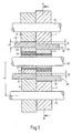
- FIG. 1 and 2 show a device according to the invention which is suitable for cutting strip-shaped flat material 30 into two parts or part strips 31, 32.
- the three knife shafts 20, 21, 22 are arranged axially parallel one above the other and lying in one plane in a stand, not shown.
- the circular knives 1, 2, 3, 4 are now pushed onto these three knife widths and attached to them as follows:
- the two counter knives 2 and 4 On the middle knife shaft 20 are the two counter knives 2 and 4 arranged next to one another. They consist of the outer cutting ring 25, an inner steel hub ring 27 and an intermediate rubber-elastic hub part 26.
- This embodiment of the counter knives 2, 4 is advantageous because the inner hub ring 27 makes it easier to attach the counter knives 2, 4 to the shaft 20.
- the two counter knives 2 and 4 assigned to circular knives 1 and 3 of conventional design - are now pushed onto and fastened to the two outer knife shafts 21 and 22 in such a way that knives 1 and 2 are the first pair of circular knives and the knives 3 and 4 form the second pair of circular knives.
- FIG. 1 the shear or. Cutting planes of the two pairs of circular knives 1, 2 and 3, 4 together.
- the strip material 30 to be cut is first introduced into the first separation stage, ie into the first pair of circular knives 1, 2, and sheared there with the deformation d.
- the cut material is then inserted by turning through 180 ° into the second separation stage, ie into the pair of circular knives 3, 4.
- the band material is then sheared again with the deformation d2, but in this case in the opposite direction, so that the band material leaves the pair of circular knives 3, 4 in the form of two completely separate parts 31 and 32.
- d, d z .
- FIG. 3 shows a device according to the invention suitable for splitting band-shaped material 30 into a multiplicity of individual bands. It consists of a variety of on the three axially parallel knife shafts 20, 21, 22 attached circular knife pairs. Again, the counter knives 2, 4, 6, 8, 10, 12, 16 of each pair of circular knives are arranged side by side on the common middle knife shaft 20. In this case there are steel spacer rings 2 ', 4', 6 ', 8', 10 'between the knives 1, 5, 9, 13 on the outer knife shaft 21 and between the knives 3, 7, 11 on the outer knife shaft 22. 12 ', 16'.
- these steel spacer rings corresponds to the width of the associated counter knives 2, 4, 6, 8, 10, 12, 16, their radius must not be greater than the radius of the knives 1, 3, 5, 7, 9, 11, 13 , minus the deformation d. If, on the other hand, their radius is advantageously chosen to be R KM -d, these steel spacer rings act as counter-holding rings, which ensure that the sheared or completely severed material remains flat over the width of these rings.
- the width of the individual bands into which the band-shaped material is split with the aid of the device according to the invention is determined by the width of the opposing counter knives and the knives on the two outer knife shafts 21 and 22.
Landscapes
- Engineering & Computer Science (AREA)
- Mechanical Engineering (AREA)
- Processing And Handling Of Plastics And Other Materials For Molding In General (AREA)
- Nonmetal Cutting Devices (AREA)
- Perforating, Stamping-Out Or Severing By Means Other Than Cutting (AREA)
Priority Applications (1)
| Application Number | Priority Date | Filing Date | Title |
|---|---|---|---|
| AT86103561T ATE35786T1 (de) | 1985-03-26 | 1986-03-17 | Vorrichtung zum gratfreien schneiden von bandfoermigem material. |
Applications Claiming Priority (2)
| Application Number | Priority Date | Filing Date | Title |
|---|---|---|---|
| DE3510847A DE3510847C1 (de) | 1985-03-26 | 1985-03-26 | Kreismesserschere zum gratfreien Schneiden von bandfoermigem Material |
| DE3510847 | 1985-03-26 |
Publications (3)
| Publication Number | Publication Date |
|---|---|
| EP0200892A2 true EP0200892A2 (fr) | 1986-11-12 |
| EP0200892A3 EP0200892A3 (en) | 1987-06-24 |
| EP0200892B1 EP0200892B1 (fr) | 1988-07-20 |
Family
ID=6266317
Family Applications (1)
| Application Number | Title | Priority Date | Filing Date |
|---|---|---|---|
| EP86103561A Expired EP0200892B1 (fr) | 1985-03-26 | 1986-03-17 | Dispositif pour couper des bandes sans bavures |
Country Status (5)
| Country | Link |
|---|---|
| US (1) | US4644837A (fr) |
| EP (1) | EP0200892B1 (fr) |
| AT (1) | ATE35786T1 (fr) |
| CA (1) | CA1262436A (fr) |
| DE (2) | DE3510847C1 (fr) |
Cited By (2)
| Publication number | Priority date | Publication date | Assignee | Title |
|---|---|---|---|---|
| RU2235624C1 (ru) * | 2003-02-10 | 2004-09-10 | ООО "Сорби стил" | Способ продольной резки металлической полосы |
| RU2506145C1 (ru) * | 2012-10-01 | 2014-02-10 | Открытое акционерное общество "Северсталь" (ОАО "Северсталь") | Способ производства полосы из рулонной заготовки |
Families Citing this family (5)
| Publication number | Priority date | Publication date | Assignee | Title |
|---|---|---|---|---|
| AT390218B (de) * | 1987-09-25 | 1990-04-10 | Boehler Gmbh | Bandfuehrung an rundmessern |
| AT390753B (de) * | 1988-04-11 | 1990-06-25 | Boehler Gmbh | Fuehrung von flaechenmaterial in anlagen mit rundmessern |
| DE4013535A1 (de) * | 1990-04-27 | 1991-10-31 | Goebel Gmbh Maschf | Einrichtung und verfahren zum bearbeiten eines substrates |
| DE19907740B4 (de) * | 1999-02-23 | 2008-02-14 | Volkswagen Ag | Verfahren zum Abtrennen eines Rohrstückes von einem zylindrischen Rohr, sowie einer Abtrennvorrichtung zur Durchführung des Verfahrens |
| CN102717142B (zh) * | 2011-08-03 | 2015-03-25 | 程乃士 | 金属带宽钢环闭环精密剪切装置 |
Family Cites Families (9)
| Publication number | Priority date | Publication date | Assignee | Title |
|---|---|---|---|---|
| US1727796A (en) * | 1928-10-20 | 1929-09-10 | Continental Can Co | Slitter cutter |
| DE1036013B (de) * | 1954-07-22 | 1958-08-07 | Eric Frank West | Kreismesserschere zum Schneiden von Blech |
| DE1806305B2 (de) * | 1968-10-31 | 1971-10-21 | Vorrichtung zum gratlosen abscheren von flachwalzmaterial | |
| US3730043A (en) * | 1970-11-09 | 1973-05-01 | Ampex | Apparatus for shearing webs |
| GB1322151A (en) * | 1971-01-06 | 1973-07-04 | Alcan Res & Dev | Method for slitting metal strip |
| US3677122A (en) * | 1971-03-23 | 1972-07-18 | Lord Corp | Slitting apparatus having independent resiliently supported anvil means |
| BR7208776D0 (pt) * | 1972-01-12 | 1973-08-30 | J Frohling | Anel ejetor para tesouras de facas circulares |
| JPS5542715A (en) * | 1978-09-14 | 1980-03-26 | Kohan Sendan Kikai Kk | Shearing device of longitudinal dividing |
| GB2108089B (en) * | 1981-09-29 | 1985-09-04 | Metal Box Plc | Apparatus for handling thin sheets of material |
-
1985
- 1985-03-26 DE DE3510847A patent/DE3510847C1/de not_active Expired
-
1986
- 1986-03-17 EP EP86103561A patent/EP0200892B1/fr not_active Expired
- 1986-03-17 DE DE8686103561T patent/DE3660394D1/de not_active Expired
- 1986-03-17 AT AT86103561T patent/ATE35786T1/de not_active IP Right Cessation
- 1986-03-19 US US06/841,510 patent/US4644837A/en not_active Expired - Fee Related
- 1986-03-25 CA CA000505013A patent/CA1262436A/fr not_active Expired
Cited By (2)
| Publication number | Priority date | Publication date | Assignee | Title |
|---|---|---|---|---|
| RU2235624C1 (ru) * | 2003-02-10 | 2004-09-10 | ООО "Сорби стил" | Способ продольной резки металлической полосы |
| RU2506145C1 (ru) * | 2012-10-01 | 2014-02-10 | Открытое акционерное общество "Северсталь" (ОАО "Северсталь") | Способ производства полосы из рулонной заготовки |
Also Published As
| Publication number | Publication date |
|---|---|
| DE3510847C1 (de) | 1986-09-11 |
| EP0200892A3 (en) | 1987-06-24 |
| CA1262436A (fr) | 1989-10-24 |
| EP0200892B1 (fr) | 1988-07-20 |
| DE3660394D1 (en) | 1988-08-25 |
| US4644837A (en) | 1987-02-24 |
| ATE35786T1 (de) | 1988-08-15 |
Similar Documents
| Publication | Publication Date | Title |
|---|---|---|
| DE2056828B2 (de) | Schneidvorrichtung zum feinstanzen | |
| EP0200892B1 (fr) | Dispositif pour couper des bandes sans bavures | |
| DE3104496C2 (de) | Trommelschere | |
| DE2301774A1 (de) | Vorrichtung zum gratfreien laengsschneiden von bandfoermigem material | |
| EP0277260A2 (fr) | Dispositif pour la coupe de matériaux en feuilles | |
| EP0275909A1 (fr) | Coupeuse pour couper longitudinalement des bandes dans des feuilles | |
| DE102017120292A1 (de) | Trennvorrichtung für Rohre | |
| DE3443849A1 (de) | Randabgratvorrichtung fuer stahlblechband | |
| DE3307767A1 (de) | Verfahren und vorrichtung zur herstellung von stahlstreifen | |
| DE2261281A1 (de) | Verfahren und vorrichtung zum gratfreien trennen von teilen, insbesondere von draht- oder stangenmaterial | |
| AT390753B (de) | Fuehrung von flaechenmaterial in anlagen mit rundmessern | |
| DE6941163U (de) | Tellerfeder und vorrichtung zu ihrer herstellung | |
| EP1235730B1 (fr) | Dispositif de separation de bandes et utilisations dudit dispositif | |
| AT389835B (de) | Verfahren zur herstellung von ritz- oder trennmessern, insbesondere fuer die holzwolle-herstellung | |
| EP0181431A2 (fr) | Procédé pour le découpage par sciage des pièces à travailler | |
| DE3420201A1 (de) | Verfahren und vorrichtung zum entfernen von ueberschussmaterial an schmiedestuecken | |
| DE1602424C3 (de) | Stanzverfahren zur Teilung von Blechbändern | |
| DE867482C (de) | Stufenloses Wechselgetriebe | |
| DE2508773B2 (fr) | ||
| AT406129B (de) | Vorrichtung zum spanabhebenden bearbeiten einer streifenförmigen werkstückfläche | |
| DE1806305C (de) | Vorrichtung zum gratlosen Abscheren von Flachwalzmaterial | |
| DE2745671C3 (de) | Zwischenring für Rollscheren | |
| EP1393868A1 (fr) | Appareil pour couper une courroie | |
| DE3022691A1 (de) | Arrondiervorrichtung fuer scharfkantige bandraender | |
| EP3406400B1 (fr) | Procédé et affûteuse destinée à l'affûtage des couteaux |
Legal Events
| Date | Code | Title | Description |
|---|---|---|---|
| PUAI | Public reference made under article 153(3) epc to a published international application that has entered the european phase |
Free format text: ORIGINAL CODE: 0009012 |
|
| AK | Designated contracting states |
Kind code of ref document: A2 Designated state(s): AT BE CH DE FR GB IT LI LU NL SE |
|
| PUAB | Information related to the publication of an a document modified or deleted |
Free format text: ORIGINAL CODE: 0009199EPPU |
|
| RA1 | Application published (corrected) |
Date of ref document: 19861217 Kind code of ref document: A2 |
|
| PUAL | Search report despatched |
Free format text: ORIGINAL CODE: 0009013 |
|
| AK | Designated contracting states |
Kind code of ref document: A3 Designated state(s): AT BE CH DE FR GB IT LI LU NL SE |
|
| 17P | Request for examination filed |
Effective date: 19870730 |
|
| 17Q | First examination report despatched |
Effective date: 19871130 |
|
| ITF | It: translation for a ep patent filed | ||
| GRAA | (expected) grant |
Free format text: ORIGINAL CODE: 0009210 |
|
| AK | Designated contracting states |
Kind code of ref document: B1 Designated state(s): AT BE CH DE FR GB IT LI LU NL SE |
|
| REF | Corresponds to: |
Ref document number: 35786 Country of ref document: AT Date of ref document: 19880815 Kind code of ref document: T |
|
| GBT | Gb: translation of ep patent filed (gb section 77(6)(a)/1977) | ||
| REF | Corresponds to: |
Ref document number: 3660394 Country of ref document: DE Date of ref document: 19880825 |
|
| ET | Fr: translation filed | ||
| PG25 | Lapsed in a contracting state [announced via postgrant information from national office to epo] |
Ref country code: LU Free format text: LAPSE BECAUSE OF NON-PAYMENT OF DUE FEES Effective date: 19890331 |
|
| PLBE | No opposition filed within time limit |
Free format text: ORIGINAL CODE: 0009261 |
|
| STAA | Information on the status of an ep patent application or granted ep patent |
Free format text: STATUS: NO OPPOSITION FILED WITHIN TIME LIMIT |
|
| 26N | No opposition filed | ||
| PGFP | Annual fee paid to national office [announced via postgrant information from national office to epo] |
Ref country code: CH Payment date: 19900222 Year of fee payment: 5 |
|
| PGFP | Annual fee paid to national office [announced via postgrant information from national office to epo] |
Ref country code: FR Payment date: 19900224 Year of fee payment: 5 |
|
| PGFP | Annual fee paid to national office [announced via postgrant information from national office to epo] |
Ref country code: BE Payment date: 19900226 Year of fee payment: 5 |
|
| PGFP | Annual fee paid to national office [announced via postgrant information from national office to epo] |
Ref country code: SE Payment date: 19900228 Year of fee payment: 5 Ref country code: LU Payment date: 19900228 Year of fee payment: 5 Ref country code: GB Payment date: 19900228 Year of fee payment: 5 Ref country code: AT Payment date: 19900228 Year of fee payment: 5 |
|
| ITTA | It: last paid annual fee | ||
| PGFP | Annual fee paid to national office [announced via postgrant information from national office to epo] |
Ref country code: NL Payment date: 19900331 Year of fee payment: 5 |
|
| PGFP | Annual fee paid to national office [announced via postgrant information from national office to epo] |
Ref country code: DE Payment date: 19900430 Year of fee payment: 5 |
|
| PG25 | Lapsed in a contracting state [announced via postgrant information from national office to epo] |
Ref country code: GB Effective date: 19910317 Ref country code: AT Effective date: 19910317 |
|
| PG25 | Lapsed in a contracting state [announced via postgrant information from national office to epo] |
Ref country code: SE Effective date: 19910318 |
|
| PG25 | Lapsed in a contracting state [announced via postgrant information from national office to epo] |
Ref country code: LI Effective date: 19910331 Ref country code: CH Effective date: 19910331 Ref country code: BE Effective date: 19910331 |
|
| BERE | Be: lapsed |
Owner name: KARL JUNGEL G.M.B.H. & CO. K.G. Effective date: 19910331 |
|
| PG25 | Lapsed in a contracting state [announced via postgrant information from national office to epo] |
Ref country code: NL Effective date: 19911001 |
|
| GBPC | Gb: european patent ceased through non-payment of renewal fee | ||
| NLV4 | Nl: lapsed or anulled due to non-payment of the annual fee | ||
| PG25 | Lapsed in a contracting state [announced via postgrant information from national office to epo] |
Ref country code: FR Effective date: 19911129 |
|
| REG | Reference to a national code |
Ref country code: CH Ref legal event code: PL |
|
| PG25 | Lapsed in a contracting state [announced via postgrant information from national office to epo] |
Ref country code: DE Effective date: 19920101 |
|
| REG | Reference to a national code |
Ref country code: FR Ref legal event code: ST |
|
| EUG | Se: european patent has lapsed |
Ref document number: 86103561.6 Effective date: 19911009 |
|
| PG25 | Lapsed in a contracting state [announced via postgrant information from national office to epo] |
Ref country code: IT Free format text: LAPSE BECAUSE OF NON-PAYMENT OF DUE FEES;WARNING: LAPSES OF ITALIAN PATENTS WITH EFFECTIVE DATE BEFORE 2007 MAY HAVE OCCURRED AT ANY TIME BEFORE 2007. THE CORRECT EFFECTIVE DATE MAY BE DIFFERENT FROM THE ONE RECORDED. Effective date: 20050317 |