EP0200671A2 - Furnace, particularly a metal-smelting or heat-retaining furnace - Google Patents
Furnace, particularly a metal-smelting or heat-retaining furnace Download PDFInfo
- Publication number
- EP0200671A2 EP0200671A2 EP86730054A EP86730054A EP0200671A2 EP 0200671 A2 EP0200671 A2 EP 0200671A2 EP 86730054 A EP86730054 A EP 86730054A EP 86730054 A EP86730054 A EP 86730054A EP 0200671 A2 EP0200671 A2 EP 0200671A2
- Authority
- EP
- European Patent Office
- Prior art keywords
- furnace
- liquid metal
- immersion
- metal bath
- metal
- Prior art date
- Legal status (The legal status is an assumption and is not a legal conclusion. Google has not performed a legal analysis and makes no representation as to the accuracy of the status listed.)
- Withdrawn
Links
Images
Classifications
-
- F—MECHANICAL ENGINEERING; LIGHTING; HEATING; WEAPONS; BLASTING
- F27—FURNACES; KILNS; OVENS; RETORTS
- F27D—DETAILS OR ACCESSORIES OF FURNACES, KILNS, OVENS OR RETORTS, IN SO FAR AS THEY ARE OF KINDS OCCURRING IN MORE THAN ONE KIND OF FURNACE
- F27D99/00—Subject matter not provided for in other groups of this subclass
- F27D99/0001—Heating elements or systems
- F27D99/0006—Electric heating elements or system
-
- F—MECHANICAL ENGINEERING; LIGHTING; HEATING; WEAPONS; BLASTING
- F27—FURNACES; KILNS; OVENS; RETORTS
- F27B—FURNACES, KILNS, OVENS OR RETORTS IN GENERAL; OPEN SINTERING OR LIKE APPARATUS
- F27B14/00—Crucible or pot furnaces
- F27B14/08—Details specially adapted for crucible or pot furnaces
- F27B14/14—Arrangements of heating devices
-
- F—MECHANICAL ENGINEERING; LIGHTING; HEATING; WEAPONS; BLASTING
- F27—FURNACES; KILNS; OVENS; RETORTS
- F27B—FURNACES, KILNS, OVENS OR RETORTS IN GENERAL; OPEN SINTERING OR LIKE APPARATUS
- F27B3/00—Hearth-type furnaces, e.g. of reverberatory type; Electric arc furnaces ; Tank furnaces
- F27B3/10—Details, accessories or equipment, e.g. dust-collectors, specially adapted for hearth-type furnaces
- F27B3/20—Arrangements of heating devices
-
- F—MECHANICAL ENGINEERING; LIGHTING; HEATING; WEAPONS; BLASTING
- F27—FURNACES; KILNS; OVENS; RETORTS
- F27B—FURNACES, KILNS, OVENS OR RETORTS IN GENERAL; OPEN SINTERING OR LIKE APPARATUS
- F27B14/00—Crucible or pot furnaces
- F27B2014/002—Smelting process, e.g. sequences to melt a specific material
-
- F—MECHANICAL ENGINEERING; LIGHTING; HEATING; WEAPONS; BLASTING
- F27—FURNACES; KILNS; OVENS; RETORTS
- F27B—FURNACES, KILNS, OVENS OR RETORTS IN GENERAL; OPEN SINTERING OR LIKE APPARATUS
- F27B14/00—Crucible or pot furnaces
- F27B14/08—Details specially adapted for crucible or pot furnaces
- F27B2014/0875—Two zones or chambers, e.g. one used for charging
-
- F—MECHANICAL ENGINEERING; LIGHTING; HEATING; WEAPONS; BLASTING
- F27—FURNACES; KILNS; OVENS; RETORTS
- F27D—DETAILS OR ACCESSORIES OF FURNACES, KILNS, OVENS OR RETORTS, IN SO FAR AS THEY ARE OF KINDS OCCURRING IN MORE THAN ONE KIND OF FURNACE
- F27D99/00—Subject matter not provided for in other groups of this subclass
- F27D99/0001—Heating elements or systems
- F27D99/0006—Electric heating elements or system
- F27D2099/0008—Resistor heating
- F27D2099/0011—The resistor heats a radiant tube or surface
- F27D2099/0013—The resistor heats a radiant tube or surface immersed in the charge
Definitions
- the invention relates to a furnace, in particular a melting or holding furnace for metal. the preamble of the main claim.
- Such furnaces are used in foundries and serve as storage furnaces or as heat-holding ladle furnaces for metal alloys at the casting station. They are loaded with the desired liquid metal alloy from a central premelting station or with the melting material via a loading device. These furnaces are kept at a certain temperature by resistance heating or also by oil or gas burners. It is also known to heat the furnace and thus the metal bath from the ceiling by heating the walls of the furnace vessel or by means of radiant heaters. For direct heating there are also immersion heaters that are inserted through the furnace wall into the interior of the furnace in the liquid metal area. In furnaces with such a heating there is the disadvantage that the immersion heaters are injured by the melting material or by the liquid material introduced. In addition, the side feed-through points have to be sealed against the liquid metal, and if they are arranged horizontally, the heating elements will wear out due to their own weight at high temperatures.
- the invention is therefore based on the object of creating a furnace, in particular a melting or holding furnace with immersion heaters, in which the wear of the immersion heaters is reduced and the service life of the entire heating arrangement is thus increased.
- the immersion heaters Due to the fact that the immersion heaters are inserted into the metal bath from above, the lead-through points lie above the liquid level, so that isolation and sealing of the lead-through points does not cause any problems.
- the vertical position of the immersion heater reduces the wear caused by its own weight at high temperatures.
- the heat transfer is improved by the exchange of the liquid material.
- Additional protection for the immersion heater against damage caused by the melting material can be provided by providing protective tubes, e.g. made of ceramic, graphite, clay or coated steel or cast iron pipes.
- the furnace 1 shown in Fig. 1 is designed as a holding furnace in which metal, e.g. Aluminum that has been melted elsewhere is introduced and the like for the purpose of further use, metering. is kept warm at a certain temperature or possibly further heated.
- the furnace 1 has a furnace vessel 2 which is largely insulated from the outside, which is lined with ceramic and is covered with a lid 3.
- the liquid metal bath 4 is filled with the molten metal via a filling opening 5, and the liquid metal is removed at a given time via the removal opening 6.
- Immersion heaters 7 are guided through the cover 3 and preferably dip vertically into the metal bath 4.
- the immersion heaters 7 are designed as resistance heaters, but they can also be designed as gas or oil heaters.
- immersion walls 8 are let into the metal bath 4 from above, which largely cover the immersion heaters 7.
- the baffles 8 can be attached to the lid 3.
- the immersion depth of the baffles 7 is dimensioned such that a sufficiently large opening for the flow of the liquid metal remains between its lower edge and the bottom of the furnace vessel 2.
- FIG. 2 shows an exemplary embodiment of a melting furnace 10, in which the furnace vessel 12 is filled with the melting material 19 via a loading device 11.
- the immersion heater 17 is in turn passed through the cover 13 and projects vertically into the liquid metal bath 14.
- the partition wall 18 divides the metal bath 14 into a heating chamber 15 and a melting chamber 16 and covers the immersion heater against the coarse-grained melting material 19 that has been filled in.
- the liquid metal is removed via a tap valve 20.
- the metal can also be taken in by scooping or by a pump.
- the baffles 8, 18 end at a sufficient distance from the bottom of the vessel 2, 12 in order to ensure a sufficient exchange of the liquid metal.
- This exchange and thus also the heat transfer can also take place via openings in the baffle 8, 18, these openings being arranged locally, for example in the vicinity of the bottom of the container 2, 12, but they can also be located on the entire surface of the partition 8 , 18 may be distributed, these openings then being adapted to the size of the melting material 19, so that the melting material 19 cannot slip through the holes.
- the immersion heaters 7, 17, can be coated with appropriately designed protective tubes, for example made of ceramic, graphite, clay or similar substances, whereby coated steel or cast iron tubes can also be used.
Landscapes
- Engineering & Computer Science (AREA)
- Mechanical Engineering (AREA)
- General Engineering & Computer Science (AREA)
- Vertical, Hearth, Or Arc Furnaces (AREA)
Abstract
Es wird ein Ofen, insbesondere ein Schmelz- oder Warmhalteofen für Metall vorgeschlagen, der ein das flüssige Metallbad (4) aufnehmendes, wärmeisoliertes Ofengefäß (1) und mindestens einen in das flüssige Metallbad (4) hineinragenden Tauchheizkörper (7) aufweist. In das flüssige Metallbad (4) ist mindestens eine Tauchwand (8) eingeführt, die den den Tauchheizkörper (7) aufnehmenden Bereich von dem übrigen Bereich des Schmelzbades abtrennt. Die Abmessungen der Tauchwand (8) ist derart gewählt, daß ein Austausch des flüssigen Metalls zwischen den Bereichen möglich ist.The invention relates to a furnace, in particular a melting or holding furnace for metal, which has a heat-insulated furnace vessel (1) that receives the liquid metal bath (4) and at least one immersion heater (7) that projects into the liquid metal bath (4). At least one immersion wall (8) is inserted into the liquid metal bath (4) and separates the area receiving the immersion heater (7) from the remaining area of the weld pool. The dimensions of the baffle (8) are chosen so that an exchange of the liquid metal between the areas is possible.
Description
Die Erfindung betrifft einen Ofen, insbesondere einen Schmelz-oder Warmhalteofen für Metall nach . dem Oberbegriff des Hauptanspruchs.The invention relates to a furnace, in particular a melting or holding furnace for metal. the preamble of the main claim.
Derartige Öfen finden in Gießereibetrieben Anwendung und dienen als Speicheröfen oder als Warmhalte-Schöpföfen für Metallegierungen am Gießplatz. Sie werden aus einer zentralen Vorschmelzstation mit der jeweils gewünschten flüssigen Metallegierung oder über ein Beschickungsgerät mit dem Schmelzgut beschickt. Diese Öfen werden durch eine Widerstandsheizung oder auch durch ÖI-oder Gasbrenner auf einer bestimmten Temperatur gehalten. Es ist auch bekannt, den Ofen und damit das Metallbad durch Beheizung der Wände des Ofengefäßes oder mittels Strahlungsheizkörpern von der Decke aus zu beheizen. Für die direkte Beheizung gibt es auch bereits Tauchheizkörper, die im Flüssigmetallbereich durch die Ofenwand in das Ofeninnere eingeführt sind. Bei Öfen mit einer derartigen Beheizung besteht der Nachteil, daß die Tauchheizkörper durch das Schmelzgut oder durch eingebrachtes Flüssigkeitsmaterial verletzt werden. Außerdem müssen die seitlichen Durchführungsstellen gegen das flüssige Metall abgedichtet werden,und bei waagerechter Anordnung tritt ein besonderer Verschleiß der Heizelemente durch ihr eigenes Gewicht bei hohen Temeperaturen auf.Such furnaces are used in foundries and serve as storage furnaces or as heat-holding ladle furnaces for metal alloys at the casting station. They are loaded with the desired liquid metal alloy from a central premelting station or with the melting material via a loading device. These furnaces are kept at a certain temperature by resistance heating or also by oil or gas burners. It is also known to heat the furnace and thus the metal bath from the ceiling by heating the walls of the furnace vessel or by means of radiant heaters. For direct heating there are also immersion heaters that are inserted through the furnace wall into the interior of the furnace in the liquid metal area. In furnaces with such a heating there is the disadvantage that the immersion heaters are injured by the melting material or by the liquid material introduced. In addition, the side feed-through points have to be sealed against the liquid metal, and if they are arranged horizontally, the heating elements will wear out due to their own weight at high temperatures.
Der Erfindung liegt daher die Aufgabe zugrunde, einen Ofen, insbesondere einen Schmelz-oder Warmhalteofen mit Tauchheizkörpern zu - schaffen, bei dem der Verschleiß der Tauchheizkörper verringert wird und somit die Lebensdauer der gesamten Heizanordnung erhöht wird.The invention is therefore based on the object of creating a furnace, in particular a melting or holding furnace with immersion heaters, in which the wear of the immersion heaters is reduced and the service life of the entire heating arrangement is thus increased.
Diese Aufgabe wird erfindungsgemäß durch die kennzeichnenden Merkmale des Hauptanspruchs in Verbindung mit den Merkmalen des Oberbegriffs gelöst. Durch Vorsehen von einer oder mehreren Tauchwänden, die den Heizbereich von dem übrigen Bereich des flüssigen Metallbades abtrennen, werden die Heizelemente bzw. Tauchheizkörper gegen Beschädigungen durch das ungeschmolzene oder auch durch das flüssige Material gut geschützt.This object is achieved according to the invention by the characterizing features of the main claim in conjunction with the features of the preamble. By providing one or more baffles which separate the heating area from the rest of the liquid metal bath, the heating elements or immersion heaters are well protected against damage from the unmelted or also from the liquid material.
Durch die in den Unteransprüchen angegebenen Maßnahmen sind vorteilhafte Weiterbildungen und Verbesserungen möglich. Dadurch, daß die Tauchheizkörper von oben her in das Metallbad eingeführt werden, liegen die Durchführungsstellen oberhalb des Flüssigkeitsspiegels, so daß eine Isolierung und Abdichtung der Durchführungsstellen keine Probleme mit sich bringt. Die senkrechte Stellung der Tauchheizkörper verringert den durch das Eigengewicht bei den hohen Temperaturen hervorgerufenen Verschleiß. Durch Vorsehen von Öffnungen in der Tauchwand wird die Wärmeübertragung durch den Austausch des flüssigen Materials verbessert. Ein zusätzlicher Schutz für die Tauchheizkörper gegen Beschädigungen durch das Schmelzgut kann durch Vorsehen von Schutzrohren, z.B. aus Keramik, Graphit, Ton oder von beschichteten Stahl-oder Gußrohren erreicht werden.Advantageous further developments and improvements are possible through the measures specified in the subclaims. Due to the fact that the immersion heaters are inserted into the metal bath from above, the lead-through points lie above the liquid level, so that isolation and sealing of the lead-through points does not cause any problems. The vertical position of the immersion heater reduces the wear caused by its own weight at high temperatures. By providing openings in the baffle, the heat transfer is improved by the exchange of the liquid material. Additional protection for the immersion heater against damage caused by the melting material can be provided by providing protective tubes, e.g. made of ceramic, graphite, clay or coated steel or cast iron pipes.
Die Erfindung ist in der Zeichnung dargestellt und wird in der nachfolgenden Beschreibung näher erläutert. Es zeigen:
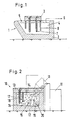
- Fig. 1 einen Schnitt durch ein erstes Ausführungsbeispiel des erfindungsgemäßen Ofens in Form eines Warmhalteofens und
- Fig. 2 einen Schnitt durch ein zweites Ausführungsbeispiel des erfindungsgemäßen Ofens in Form eines Schmelzofens.
- Fig. 1 shows a section through a first embodiment of the furnace according to the invention in the form of a holding furnace and
- Fig. 2 shows a section through a second embodiment of the furnace according to the invention in the form of a melting furnace.
Der in Fig. 1 dargestellte Ofen 1 ist als Warmhalteofen ausgebildet, in den Metall, z.B. Aluminium, das an anderer Stelle geschmolzen worden ist, eingebracht wird und zum Zwecke der Weiterverwendung, Dosierung od.dgl. auf einer bestimmten Temperatur warmgehalten oder gegebenenfalls noch weiter aufgeheizt wird. Der Ofen 1 weist ein nach außen weitgehend wärmeisoliertes Ofengefäß 2 auf, das keramisch ausgekleidet ist und mit einem Deckel 3 abgedeckt ist. Das flüssige Metallbad 4 wird über eine Einfüllöffnung 5 mit dem geschmolzenen Metall aufgefüllt, und über die Entnahmeöffnung 6 wird das flüssige Metall zu gegebener Zeit entnommen. Durch den Deckel 3 hindurchgeführt sind Tauchheizkörper 7, die vorzugsweise senkrecht in das Metallbad 4 hineintauchen. Die Tauchheizkörper 7 sind als Widerstandsheizkörper ausgebildet, sie können aber auch als Gas-oder Ölheizkörper ausgebildet sein. Um die Tauchheizkörper 7 gegen Beschädigungen zu - schützen, insbesondere an den Einfüll-und Entnahmeöffnungen 5 und 6, sind von oben her Tauchwände 8 in das Metallbad 4 eingelassen, die die Tauchheizkörper 7 weitgehend abdecken. Die Tauchwände 8 können an den Deckel 3 befestigt sein. Die Eintauchtiefe der Tauchwände 7 ist so bemessen, daß zwischen ihrer Unterkante und dem Boden des Ofengefäßes 2 eine ausreichend große Öffnung für den Durchfluß des flüssigen Metalls bestehen bleibt.The
In Fig. 2 ist ein Ausführungsbeispiel für einen Schmelzofen 10 dargestellt, bei dem das Ofengefäß 12 über ein Beschickungsgerät 11 mit dem Schmelzgut 19 gefüllt wird. Der Tauchheizkörper 17 ist wiederum durch den Deckel 13 hindurchgeführt und ragt senkrecht in das flüssige Metallbad 14 hinein. Die Trennwand 18 unterteilt das Metallbad 14 in einen Heizraum 15 und einen Schmelzraum 16 und deckt den Tauchheizkörper gegen das eingefüllte grobkörnige Schmelzgut 19 ab. Über ein Abstichventil 20 wird das flüssige Metall entnommen. Das Metall kann auch durch Schöpfen oder durch eine Pumpe augenommen werden. In den dargestellten Ausführungsbeispielen enden die Tauchwände 8, 18 mit genügendem Abstand zum Boden des Gefäßes 2, 12, um einen ausreichenden Austausch des flüssigen Metalls zu gewährleisten. Dieser Austausch und damit auch die Wärmeübertragung kann aber auch über Öffnungen in der Tauchwand 8, 18 erfolgen, wobei diese Öffnungen lokal, beispielsweise in der Nähe des Bodens des Grfäßes 2, 12 angeordnet sein, sie können aber auch auf der gesamten Oberfläche der Trennwand 8, 18 verteilt sein, wobei diese Öffnungen dann an die Größe des Schmelzgutes 19 angepaßt sein sollten, damit das Schmelzgut 19 nicht durch die Löcher hindurchrutschen kann.2 shows an exemplary embodiment of a
Um die Tauchheizkörper 7, 17 weiterhin zu - schützen, können die Tauchheizkörper mit entsprechend ausgebildeten Schutzrohren, beispielsweise aus Keramik, Graphit, Ton oder ähnlichen Stoffen überzogen werden, wobei auch beschichtete Stahl oder Gußrohre verwendet werden können.In order to further protect the
Claims (4)
Applications Claiming Priority (2)
| Application Number | Priority Date | Filing Date | Title |
|---|---|---|---|
| DE19853512868 DE3512868A1 (en) | 1985-04-04 | 1985-04-04 | OVEN, ESPECIALLY MELTING OR WARMING OVEN FOR METAL |
| DE3512868 | 1985-04-04 |
Publications (2)
| Publication Number | Publication Date |
|---|---|
| EP0200671A2 true EP0200671A2 (en) | 1986-11-05 |
| EP0200671A3 EP0200671A3 (en) | 1987-06-10 |
Family
ID=6267643
Family Applications (1)
| Application Number | Title | Priority Date | Filing Date |
|---|---|---|---|
| EP86730054A Withdrawn EP0200671A3 (en) | 1985-04-04 | 1986-03-25 | Furnace, particularly a metal-smelting or heat-retaining furnace |
Country Status (2)
| Country | Link |
|---|---|
| EP (1) | EP0200671A3 (en) |
| DE (1) | DE3512868A1 (en) |
Cited By (5)
| Publication number | Priority date | Publication date | Assignee | Title |
|---|---|---|---|---|
| FR2647886A1 (en) * | 1989-06-06 | 1990-12-07 | Jafs Export Oy Holimesy Ab | FOUNDRY OVEN |
| GB2232751A (en) * | 1989-06-06 | 1990-12-19 | Christopher J English | Apparatus and method for treating molten material |
| WO1995013402A1 (en) * | 1993-11-12 | 1995-05-18 | Pechiney Rhenalu | Compact molten metal processing ladle |
| DE4039801C2 (en) * | 1990-01-25 | 2000-03-16 | Abb Kk | Influencing the exhaust gas flow in a melting furnace |
| CN105466215A (en) * | 2015-12-25 | 2016-04-06 | 重庆唐森机械制造有限公司 | Heating furnace for production of energy-saving pan |
Families Citing this family (2)
| Publication number | Priority date | Publication date | Assignee | Title |
|---|---|---|---|---|
| FR2650380A1 (en) * | 1989-07-28 | 1991-02-01 | Air Liquide | METHOD FOR HEATING A METAL BATH |
| US5948352A (en) * | 1996-12-05 | 1999-09-07 | General Motors Corporation | Two-chamber furnace for countergravity casting |
Family Cites Families (5)
| Publication number | Priority date | Publication date | Assignee | Title |
|---|---|---|---|---|
| DE645671C (en) * | 1934-04-17 | 1937-06-01 | Siegfried Junghans | Electric furnace for melting metals |
| FR870310A (en) * | 1940-03-01 | 1942-03-09 | Licentia Gmbh | Electric furnace with fusible salt bath, with electrodes |
| US3996412A (en) * | 1975-01-17 | 1976-12-07 | Frank W. Schaefer, Inc. | Aluminum melting furnace |
| GB1561786A (en) * | 1976-12-09 | 1980-03-05 | Ass Eng Ltd | Heating vessles for molten metal |
| FR2480419A1 (en) * | 1980-04-09 | 1981-10-16 | Mgr Sa Fours | INSTALLATION AND METHOD FOR MELTING OR MAINTAINING A METAL MATERIAL BY IMMERSION RESISTANT ELEMENT IN METAL |
-
1985
- 1985-04-04 DE DE19853512868 patent/DE3512868A1/en not_active Withdrawn
-
1986
- 1986-03-25 EP EP86730054A patent/EP0200671A3/en not_active Withdrawn
Cited By (11)
| Publication number | Priority date | Publication date | Assignee | Title |
|---|---|---|---|---|
| FR2647886A1 (en) * | 1989-06-06 | 1990-12-07 | Jafs Export Oy Holimesy Ab | FOUNDRY OVEN |
| GB2232752A (en) * | 1989-06-06 | 1990-12-19 | Jafs Export Oy Holimesy Ab | Metalmelting furnace |
| GB2232751A (en) * | 1989-06-06 | 1990-12-19 | Christopher J English | Apparatus and method for treating molten material |
| US5164146A (en) * | 1989-06-06 | 1992-11-17 | Ab Jafs Export Oy Holimesy | Foundry furnace having outlet flow passage |
| GB2232752B (en) * | 1989-06-06 | 1993-05-12 | Jafs Export Oy Holimesy Ab | Foundry furnace |
| DE4039801C2 (en) * | 1990-01-25 | 2000-03-16 | Abb Kk | Influencing the exhaust gas flow in a melting furnace |
| WO1995013402A1 (en) * | 1993-11-12 | 1995-05-18 | Pechiney Rhenalu | Compact molten metal processing ladle |
| FR2712217A1 (en) * | 1993-11-12 | 1995-05-19 | Pechiney Rhenalu | Pocket for processing liquid metal with a small footprint and improved performance. |
| US5494265A (en) * | 1993-11-12 | 1996-02-27 | Pechiney Rhenalu | Ladle for processing molten metal with minimal space requirements and improved performance |
| CN105466215A (en) * | 2015-12-25 | 2016-04-06 | 重庆唐森机械制造有限公司 | Heating furnace for production of energy-saving pan |
| CN105466215B (en) * | 2015-12-25 | 2017-08-11 | 重庆唐森机械制造有限公司 | A kind of energy saving pot production heating furnace |
Also Published As
| Publication number | Publication date |
|---|---|
| DE3512868A1 (en) | 1986-10-09 |
| EP0200671A3 (en) | 1987-06-10 |
Similar Documents
| Publication | Publication Date | Title |
|---|---|---|
| DE2736793A1 (en) | DEVICE FOR REFINING MELT LIQUID METAL | |
| DE2944269C3 (en) | Furnace vessel of a tiltable arc furnace | |
| DE1227926B (en) | Coreless induction melting and / or holding furnace, in particular operated with mains frequency, for vacuum operation | |
| EP0200671A2 (en) | Furnace, particularly a metal-smelting or heat-retaining furnace | |
| DE1965136B1 (en) | Device for ladle degassing of steel or other metal melts | |
| EP0160185A1 (en) | Tiltable metallurgical furnace vessel | |
| DE8510534U1 (en) | Furnace, especially melting or holding furnace for metal | |
| EP0085461B1 (en) | Liquid-cooled side walls for electric-arc furnaces | |
| DE3024709C2 (en) | ||
| DE19647313A1 (en) | Method and device for the directional solidification of a melt | |
| EP1410861A1 (en) | Molten metal vessel | |
| DE1800388A1 (en) | Transfer container for molten metal pouring devices | |
| DE2135289C3 (en) | Intermediate container for charging a continuous casting mold | |
| DE1960283A1 (en) | Vacuum degassing apparatus for use in continuous casting of metals and methods of continuously casting molten metal while it is being vacuum degassed | |
| DE1083509B (en) | Electric multi-chamber melting furnace for melting down metals with a melting chamber and a holding and removal chamber | |
| DE1084446B (en) | Device for pouring molten metals of high temperature from a container with a pouring opening arranged in the bottom of the container, which drains into a heatable pouring pipe | |
| DE752170C (en) | Electric melting furnace for light metals | |
| EP1088112B1 (en) | Water-cooled vessel for vacuum processing of liquid steel | |
| DE2750674A1 (en) | SLIDING CLOSURE FOR METALLURGICAL VESSELS, ESPECIALLY FOR MELTING OR WARMING OVENS | |
| EP0072769B1 (en) | Method and device for induction heating of molten metals | |
| DE739629C (en) | Tiltable device for casting gases sensitive metals, e.g. Beryllium, in a high vacuum | |
| DE1758297B1 (en) | TRANSPORT PAN FOR MOLTEN METAL | |
| DE3633516C2 (en) | ||
| DE941314C (en) | Pan for zinc and other molten metals | |
| DE1533933C3 (en) | Device for degassing molten steel |
Legal Events
| Date | Code | Title | Description |
|---|---|---|---|
| PUAI | Public reference made under article 153(3) epc to a published international application that has entered the european phase |
Free format text: ORIGINAL CODE: 0009012 |
|
| AK | Designated contracting states |
Kind code of ref document: A2 Designated state(s): AT BE CH DE FR GB IT LI LU NL SE |
|
| PUAB | Information related to the publication of an a document modified or deleted |
Free format text: ORIGINAL CODE: 0009199EPPU |
|
| RA1 | Application published (corrected) |
Date of ref document: 19861210 Kind code of ref document: A2 |
|
| PUAL | Search report despatched |
Free format text: ORIGINAL CODE: 0009013 |
|
| AK | Designated contracting states |
Kind code of ref document: A3 Designated state(s): AT BE CH DE FR GB IT LI LU NL SE |
|
| RBV | Designated contracting states (corrected) |
Designated state(s): AT BE CH DE FR GB IT LI NL SE |
|
| 17P | Request for examination filed |
Effective date: 19871210 |
|
| 17Q | First examination report despatched |
Effective date: 19890126 |
|
| STAA | Information on the status of an ep patent application or granted ep patent |
Free format text: STATUS: THE APPLICATION HAS BEEN WITHDRAWN |
|
| 18W | Application withdrawn |
Withdrawal date: 19891023 |
|
| R18W | Application withdrawn (corrected) |
Effective date: 19891023 |
|
| RIN1 | Information on inventor provided before grant (corrected) |
Inventor name: SCHMIDT, GUENTHER |