EP0199457B1 - Méthode de commande pour l'alimentation de carburant pour moteurs à combustion interne en cas de basse température - Google Patents
Méthode de commande pour l'alimentation de carburant pour moteurs à combustion interne en cas de basse température Download PDFInfo
- Publication number
- EP0199457B1 EP0199457B1 EP86301976A EP86301976A EP0199457B1 EP 0199457 B1 EP0199457 B1 EP 0199457B1 EP 86301976 A EP86301976 A EP 86301976A EP 86301976 A EP86301976 A EP 86301976A EP 0199457 B1 EP0199457 B1 EP 0199457B1
- Authority
- EP
- European Patent Office
- Prior art keywords
- engine
- value
- fuel
- temperature
- intake air
- Prior art date
- Legal status (The legal status is an assumption and is not a legal conclusion. Google has not performed a legal analysis and makes no representation as to the accuracy of the status listed.)
- Expired - Lifetime
Links
Images

Classifications
-
- F—MECHANICAL ENGINEERING; LIGHTING; HEATING; WEAPONS; BLASTING
- F02—COMBUSTION ENGINES; HOT-GAS OR COMBUSTION-PRODUCT ENGINE PLANTS
- F02D—CONTROLLING COMBUSTION ENGINES
- F02D41/00—Electrical control of supply of combustible mixture or its constituents
- F02D41/02—Circuit arrangements for generating control signals
- F02D41/04—Introducing corrections for particular operating conditions
- F02D41/06—Introducing corrections for particular operating conditions for engine starting or warming up
- F02D41/068—Introducing corrections for particular operating conditions for engine starting or warming up for warming-up
-
- F—MECHANICAL ENGINEERING; LIGHTING; HEATING; WEAPONS; BLASTING
- F02—COMBUSTION ENGINES; HOT-GAS OR COMBUSTION-PRODUCT ENGINE PLANTS
- F02D—CONTROLLING COMBUSTION ENGINES
- F02D41/00—Electrical control of supply of combustible mixture or its constituents
- F02D41/24—Electrical control of supply of combustible mixture or its constituents characterised by the use of digital means
- F02D41/2406—Electrical control of supply of combustible mixture or its constituents characterised by the use of digital means using essentially read only memories
- F02D41/2425—Particular ways of programming the data
- F02D41/2429—Methods of calibrating or learning
- F02D41/2432—Methods of calibration
-
- F—MECHANICAL ENGINEERING; LIGHTING; HEATING; WEAPONS; BLASTING
- F02—COMBUSTION ENGINES; HOT-GAS OR COMBUSTION-PRODUCT ENGINE PLANTS
- F02D—CONTROLLING COMBUSTION ENGINES
- F02D41/00—Electrical control of supply of combustible mixture or its constituents
- F02D41/24—Electrical control of supply of combustible mixture or its constituents characterised by the use of digital means
- F02D41/2406—Electrical control of supply of combustible mixture or its constituents characterised by the use of digital means using essentially read only memories
- F02D41/2425—Particular ways of programming the data
- F02D41/2429—Methods of calibrating or learning
- F02D41/2451—Methods of calibrating or learning characterised by what is learned or calibrated
Definitions
- This invention relates to a method of controlling the quantity of fuel being supplied to an internal combustion engine when the engine is in a cold state.
- a fuel supply control method for internal combustion engines has been proposed, e.g. by Japanese Provisional Patent Publication (Kokai) No. 57-137633, which is adapted to control the air-fuel ratio of an air-fuel mixture being supplied to an internal combustion engine by electrically controlling the valve opening period of a fuel injection valve through which fuel is supplied to the engine, that is, by controlling the fuel injection quantity.
- the valve opening period of the fuel injection valve is determined by adding values of various correction variables such as an intake air temperature-dependent correction variable and a warming-up fuel increasing correction variable to and/or multiplying thereby a basic value of valve opening period corresponding to the engine rotational speed and a parameter representing the engine load, e.g. intake pipe absolute pressure.
- various correction variables such as an intake air temperature-dependent correction variable and a warming-up fuel increasing correction variable
- the intake air temperature-dependent correction variable is used to correct the basic value in order to compensate for a change in the air density caused by deviation of the intake air temperature from the predetermined reference value.
- the warming-up fuel increasing correction variable is used to correct the basic value to compensate for the difference.
- the warming-up fuel increasing correction variable is determined based not only on engine temperature, e.g. engine cooling water (coolant) temperature, but also on the intake pipe absolute pressure, because, even if the engine temperature remains unchanged, a change in the intake pipe absolute pressure, i.e., a change in the flow rate of air in the intake pipe can result in a corresponding change in the quantity of fuel adhering to the intake pipe wall as well as a change in the fuel atomization degree.
- a method of controlling the quantity of fuel being supplied to an internal combustion engine in a cold state wherein a basic value of the quantity of fuel being supplied to said engine is corrected to an increased value by the use of a fuel increasing correction variable which is set based upon a temperature of said engine and a load on said engine, said method including detecting a temperature of intake air being supplied to said engine, characterized by the steps of (1) correcting said fuel increasing correction variable in dependence on said intake air temperature detected, in a manner such that said fuel increasing correction variable is corrected to a larger value as said intake air temperature detected is lower, and (2) applying said fuel increasing correction variable exclusively when said engine is in said cold state, to correct said basic value of the quantity of fuel to an increased value.
- a method of controlling the quantity of fuel being supplied to an internal combustion engine in a cold state wherein a basic value of the quantity of fuel being supplied to said engine is corrected by the use of a first correction value which is set based upon a difference between a predetermined value and an actual value of temperature of intake air being supplied to said engine and a second correction value which is set based upon a temperature of said engine and a load on said engine, said second correction value being applied exclusively when said engine is in said cold state, to correct said basic value of the quantity of fuel to an increased value
- said method including detecting a temperature of intake air being supplied to said engine, characterized by correcting said second correction value by said intake air temperature detected in a manner such that said second correction value is corrected to a larger value as said intake air temperature detected is lower.
- the intake air temperature as one of the determinants of the engine temperature-dependent fuel increasing correction variable it is possible to correct the fuel increasing correction variable to correct for variations in the atomization degree of injected fuel with variations in the intake air temperature, thereby improving the driveability of the engine.
- GB-A-2120417 discloses determining basic fuel injection amounts corrected by an intake air temperature dependent correction coefficient KTA and a fuel increasing coefficient KTW (Equation 3). The latter is dependent on engine load PB and engine temperature TW when the engine is cold and is unity and without effect when the engine is hot (Fig. 4). A difference between the preferred embodiment of the present invention and the disclosure of this prior document is illustrated by the following:
- An intake air temperature correction value corresponding to KTA is a feature of claim 5 below but not of claim 1.
- the fuel increasing correction variable is corrected to a larger value as the intake air temperature detected is lower.
- the temperature of the engine is preferably the temperature of engine coolant.
- the load on the engine is preferably the absolute pressure in an intake pipe of the engine.
- the fuel increasing correction variable is a coefficient by which the basic value is multiplied.
- FIG. 1 there is illustrated the whole arrangement of an internal combustion engine equipped with a fuel supply control system to which the method of the present invention is applied.
- Reference numeral 1 designates the engine which may be a four cylinder type.
- Connected to each cylinder are an intake pipe 2 and an exhaust pipe 3.
- Fuel injection valves 4 are inserted in the intake pipe 2 in the vicinity of the engine 1, and an air cleaner 5 is provided at an inlet end of the intake pipe 2 opening into the atmosphere.
- a throttle valve 6 Arranged across the intake pipe 2 at a location upstream of the fuel injection valves 4 is a throttle valve 6, to which a throttle valve opening (6TH) sensor 7 is connected for detecting the valve opening.
- the throttle valve opening sensor 7 converts the detected throttle valve opening into an electrical signal to supply same to an electronic control unit (hereinafter called "ECU”) 8 to which it is electrically connected.
- ECU electronice control unit
- An absolute pressure (PBA) sensor 10 communicates through a conduit 9 with the interior of the intake pipe 2 at a location between the throttle valve 6 and the fuel injection valves 4, to detect the absolute pressure in the intake pipe 2 and convert same into an electrical signal to supply same to the ECU 8, to which it is connected.
- PBA absolute pressure
- an intake air temperature (TA) sensor 11 is inserted in the intake pipe 2 at a location between the conduit 9 and the fuel injection valves 4, to detect the temperature of intake air passing in the intake pipe 2 and convert the detected intake air temperature into an electrical signal to supply to the ECU 8, to which it is also connected.
- TA intake air temperature
- the fuel injection valves 4 are each connected to a fuel pump (not shown), and electrically connected to the ECU 8 to have its valve opening period controlled by a driving signal supplied from the ECU 8.
- the latter 13 is adapted to detect the temperature of engine cooling water (coolant) as an engine temperature and convert same into an electrical signal to supply to the ECU 8, to which it is electrically connected.
- the engine rotational speed sensor 12 is adapted to generate one pulse of a crank-angle- position signal (hereinafter called "TDC signal") at a particular crank angle position of each cylinder before a top-dead-center of the cylinder corresponding to the start of the suction stroke each time the engine crankshaft rotates through 180 degrees.
- TDC signal a crank-angle- position signal
- An 0 2 sensor 14 is inserted in the exhaust pipe 3 for detecting oxygen concentration in the exhaust gases and converting same into an electrical signal to supply to the ECU 8, to which it is electrically connected.
- a three-way catalyst 15 is arranged across the exhaust pipe 3 at a location downstream of the 0 2 sensor 14 for purifying ingredients HC, CO and NOx contained in the exhaust gases.
- other parameter sensors 16 such as an atmospheric pressure sensor for detecting atmospheric pressure, and a starting switch 17 for actuating the engine 1, the other parameter sensors 16 being also electrically connected to the ECU 8 to supply same with respective electrical signals representing the detected values.
- the ECU 8 comprises an input circuit 8a having such functions as shaping the waveforms of signals inputted from various sensors, shifting the voltage levels of other input signals to a predetermined level, and converting the values of analog signals into digital values, a central processing unit (hereinafter called "CPU") 8b, storage means 8c for storing various calculation programs to be executed in the CPU 8b, the results of calculations, etc., and an output circuit 8d having such functions as supplying the fuel injection valves 6 with driving signals to open them in response to the results of calculations.
- CPU central processing unit
- the respective engine parameter signals from the aforementioned sensors and the on-off signal from the starting switch 17 are supplied to the CPU 8b through the input circuit 8a in the ECU 8.
- the CPU 8b determines operating conditions of the engine by processing the engine parameter signal values and the on-off signal value through a predetermined control program, and calculates the quantity of fuel to be supplied to the engine 1, i.e., the fuel injection period TOUT of the fuel injection valves 4, and then supplies the fuel injection valves 4 via the output circuit 8d with the driving signals to drive same in response to the result of the calculation.
- the fuel injection period TOUT for the fuel injection valves 4 is calculated by the following equation (1): where Ti is a basic value of the fuel injection period, for which a plurality of predetermined values are stored in the storage means 8c in the ECU 8, each of the predetermined values corresponding to a respective one of combinations of values of intake pipe absolute pressure PBA and engine rotational speed Ne and being set at such a value as to supply an optimal fuel quantity on condition that the intake air temperature TA and the engine cooling water temperature TW assume respective predetermined reference values.
- the basic value Ti is set to a value read from the storage means 8c in response to the values PBA and Ne detected.
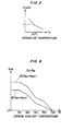
- KTA is an intake air temperature correction coefficient to compensate for a deviation of the detected intake air temperature from the predetermined reference value (e.g. 30°C), the value of the coefficient KTA is read from a table as shown in Fig. 2 in response to the intake air temperature TA detected.
- KTW is a warming-up fuel increasing correction coefficient, or a coolant temperature-dependent fuel increasing correction coefficient, which will be described later in detail.
- K1 and K2 are a correction coefficient and a correction variable, respectively, which are determined as functions of the values of various engine parameters except for the intake air temperature TA and the engine temperature TW, and are set to such values as to achieve optimal operating characteristics of the engine such as fuel consumption and emission characteristics.
- the engine coolant temperature-dependent fuel increasing correction coefficient KTW is read from tables shown in Figs. 3 and 4, for instance.
- Figs. 3 and 4 show examples of the relationship between the engine water temperature TW and the engine coolant temperature-dependent fuel increasing correction coefficient KTW.
- Fig. 3 is applied when the intake air temperature TA is equal to or lower than a predetermined value TAS (e.g. 20°C), and Fig. 4 when the intake air temperature TA exceeds the predetermined value TAS. It is so arranged that the value KTW read from Fig. 3 is greater than that read from Fig. 4 at the same value of engine water temperature TW and the same value of intake pipe absolute pressure PBA.
- TAS e.g. 20°C
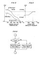
- step 1 in Fig. 6 it is determined at step 1 in Fig. 6 whether or not the actual intake air temperature TA is higher than the predetermined value TAS. If the answer is negative (No), the program proceeds to step 2, where a value of the engine coolant temperature-dependent fuel increasing correction coefficient KTW is read from the table of Fig. 3 based on the detected intake pipe absolute pressure PBA and the detected engine water temperature TW. If the answer is affirmative (Yes), the program proceeds to step 3, where a value of the correction coefficient KTW is read from the table of Fig. 4 based on the detected intake pipe absolute pressure PBA and the detected engine water temperature TW.
- the curve 1 indicates values KTWPBA1 to be selected at a first predetermined value PBA1 of intake pipe absolute pressure (e.g. 300 mmHg), and II values KTWPBA2 to be selected at a second predetermined value PBA2 of intake pipe absolute pressure (e.g. 650 mmHg), respectively.
- values KTWPBA, and KTWPBA 2 are selectively read in response to the detected water temperature TW, depending upon the detected intake pipe absolute pressure.
- a predetermined value TW 5 e.g. 60°C
- the values KTWPBA, and KTWPBA 2 are read as 1.0.
- the coolant temperature-dependent fuel increasing correction coefficient KTW is finally obtained in response to the actual intake pipe absolute pressure PBA as shown by Fig. 5.
- the intake pipe absolute pressure PBA is equal or or greater than the second predetermined intake pipe absolute pressure value PBA 2 (e.g. 650 mmHg)
- the value KTW is read as KTWPBA 2
- the intake pipe absolute pressure PBA is equal to or less than the first predetermined intake pipe absolute pressure value PBA, (e.g. 300 mmHg)
- the value KTW is read as KTWPBA 1 .
- the value KTW is set to a value intermediate between KTWPBA, and KTWPBA 2 by means of linear interpolation.
- TW-KTW tables for determining the KTW value as stated above, which are selected depending upon whether the intake air temperature TA is above or below the predetermined value TAS
- a three-dimensional table may be used, which employs intake air temperature TA, engine cooling water temperature TW, and intake pipe absolute pressure PBA, as parameters for determining the KTW value, from which table the KTW value can be directly read in response to a combination of the detected values of these parameters.
- fuel increasing correction coefficient KTW interpolation may be conducted with regard to intake pipe absolute pressure PBA before conducting interpolation with regard to engine cooling water temperature TW.
- parameter representing the engine load may be throttle valve opening or intake air quantity in lieu of intake pipe absolute pressure.
- a warming-up or engine temperature-dependent fuel increasing correction coefficient (engine coolant temperature dependent fuel increasing correction coefficient), which is one of the factors to determine a desired quantity of fuel to be supplied to an internal combustion engine, is set to an appropriate value as a fucntion of intake air temperature as well as engine temperature (engine coolant temperature) and intake pipe absolute pressure, to thereby enable compensation for a change in the atomization degree of the injected fuel caused by variation in the intake air temperature and hence prevent the atomization degree change from affecting the engine operating condition, whereby the engine rotation is stabilized and the driveability is improved.
- engine coolant temperature dependent fuel increasing correction coefficient which is one of the factors to determine a desired quantity of fuel to be supplied to an internal combustion engine
Claims (5)
Applications Claiming Priority (2)
| Application Number | Priority Date | Filing Date | Title |
|---|---|---|---|
| JP52508/85 | 1985-03-18 | ||
| JP60052508A JPS61212639A (ja) | 1985-03-18 | 1985-03-18 | 内燃エンジンの冷間時の燃料供給制御方法 |
Publications (2)
| Publication Number | Publication Date |
|---|---|
| EP0199457A1 EP0199457A1 (fr) | 1986-10-29 |
| EP0199457B1 true EP0199457B1 (fr) | 1990-01-24 |
Family
ID=12916669
Family Applications (1)
| Application Number | Title | Priority Date | Filing Date |
|---|---|---|---|
| EP86301976A Expired - Lifetime EP0199457B1 (fr) | 1985-03-18 | 1986-03-18 | Méthode de commande pour l'alimentation de carburant pour moteurs à combustion interne en cas de basse température |
Country Status (3)
| Country | Link |
|---|---|
| US (1) | US4711217A (fr) |
| EP (1) | EP0199457B1 (fr) |
| JP (1) | JPS61212639A (fr) |
Families Citing this family (9)
| Publication number | Priority date | Publication date | Assignee | Title |
|---|---|---|---|---|
| DE3903234A1 (de) * | 1989-02-03 | 1990-08-09 | Hella Kg Hueck & Co | Einrichtung zur regelung der ansauggemischtemperatur einer brennkraftmaschine, insbesondere in kraftfahrzeugen |
| EP0482048B1 (fr) * | 1989-07-14 | 1995-04-19 | Siemens Aktiengesellschaft | Procede pour la commande d'un moteur a combustion interne |
| DE69216523T2 (de) * | 1991-10-03 | 1997-04-24 | Honda Motor Co Ltd | Kraftstoffeinspritzsteuerungsvorrichtung für Brennkraftmaschinen |
| FR2697290B1 (fr) * | 1993-03-23 | 1994-12-30 | Siemens Automotive Sa | Procédé de calcul du temps d'ouverture d'au moins un injecteur de carburant, pour moteur à combustion interne. |
| DE19963931A1 (de) * | 1999-12-31 | 2001-07-12 | Bosch Gmbh Robert | Verfahren zum Warmlaufen einer Brennkraftmaschine |
| JP4123244B2 (ja) * | 2005-03-30 | 2008-07-23 | トヨタ自動車株式会社 | 内燃機関の燃料噴射制御装置 |
| KR100666107B1 (ko) * | 2005-08-30 | 2007-01-09 | 현대자동차주식회사 | 엘피아이 엔진의 연료제어방법 |
| GB2439566A (en) * | 2006-06-28 | 2008-01-02 | Ford Global Tech Llc | Cold adaptive fuelling |
| US9926870B2 (en) * | 2010-09-08 | 2018-03-27 | Honda Motor Co, Ltd. | Warm-up control apparatus for general-purpose engine |
Family Cites Families (8)
| Publication number | Priority date | Publication date | Assignee | Title |
|---|---|---|---|---|
| JPS5827845A (ja) * | 1981-08-13 | 1983-02-18 | Toyota Motor Corp | 内燃機関の燃料供給量制御方法 |
| JPS5888427A (ja) * | 1981-11-20 | 1983-05-26 | Honda Motor Co Ltd | 吸気温度による補正機能を有する内燃エンジンの空燃比補正装置 |
| JPS58187534A (ja) * | 1982-04-28 | 1983-11-01 | Honda Motor Co Ltd | 内燃エンジンの燃料供給制御方法 |
| JPS58202336A (ja) * | 1982-05-20 | 1983-11-25 | Honda Motor Co Ltd | 温度センサ異常時の燃料供給制御方法 |
| JPS5932628A (ja) * | 1982-08-16 | 1984-02-22 | Honda Motor Co Ltd | 内燃エンジンの燃料供給装置の制御方法 |
| JPS59103940A (ja) * | 1982-12-06 | 1984-06-15 | Toyota Motor Corp | 内燃機関の始動燃料制御方法 |
| JPS6095166A (ja) * | 1983-10-31 | 1985-05-28 | Nissan Motor Co Ltd | 始動空燃比制御装置 |
| JPS6165037A (ja) * | 1984-09-06 | 1986-04-03 | Toyota Motor Corp | 内燃機関の空燃比制御方法 |
-
1985
- 1985-03-18 JP JP60052508A patent/JPS61212639A/ja active Pending
-
1986
- 1986-03-17 US US06/840,460 patent/US4711217A/en not_active Expired - Lifetime
- 1986-03-18 EP EP86301976A patent/EP0199457B1/fr not_active Expired - Lifetime
Also Published As
| Publication number | Publication date |
|---|---|
| US4711217A (en) | 1987-12-08 |
| JPS61212639A (ja) | 1986-09-20 |
| EP0199457A1 (fr) | 1986-10-29 |
Similar Documents
| Publication | Publication Date | Title |
|---|---|---|
| US5158063A (en) | Air-fuel ratio control method for internal combustion engines | |
| US4454854A (en) | Exhaust gas recirculation control method for internal combustion engines for vehicles | |
| US4492203A (en) | Fuel supply control method for an internal combustion engine equipped with a supercharger, having a fail-safe function for abnormality in intake passage pressure sensor means | |
| US4471742A (en) | Fuel supply control method for an internal combustion engine equipped with a supercharger | |
| US4582036A (en) | Fuel supply control method for internal combustion engines immediately after cranking | |
| US4589390A (en) | Air-fuel ratio feedback control method for internal combustion engines | |
| US4508087A (en) | Method for controlling fuel supply to an internal combustion engine after termination of fuel cut | |
| US4478194A (en) | Fuel supply control method for internal combustion engines immediately after cranking | |
| US4765301A (en) | Fuel supply control method for internal combustion engines after starting | |
| EP0199457B1 (fr) | Méthode de commande pour l'alimentation de carburant pour moteurs à combustion interne en cas de basse température | |
| GB2370644A (en) | Barometric pressure estimation in an engine control system | |
| US4754736A (en) | Method of controlling the fuel supply to internal combustion engines at acceleration | |
| US4466411A (en) | Air/fuel ratio feedback control method for internal combustion engines | |
| US4878472A (en) | Air-fuel ratio feedback control method for internal combustion engines | |
| US4765300A (en) | Fuel supply control method for internal combustion engines after starting in hot state | |
| US5899192A (en) | Fuel supply control system for internal combustion engines | |
| US4699111A (en) | Air-fuel ratio control method for internal combustion engines | |
| US4744345A (en) | Air-fuel ratio feedback control method for internal combustion engines | |
| EP0156356B1 (fr) | Méthode de contrôle de l'alimentation en carburant d'un moteur à combustion interne | |
| US4697568A (en) | Fuel injection timing control method for internal combustion engines | |
| US5601064A (en) | Fuel injection control system for internal combustion engines | |
| US4751906A (en) | Air-fuel ratio control method for internal combustion engines | |
| US4572129A (en) | Air-fuel ratio feedback control method for internal combustion engines | |
| US4502448A (en) | Method for controlling control systems for internal combustion engines immediately after termination of fuel cut | |
| US4982714A (en) | Air-fuel control apparatus for an internal combustion engine |
Legal Events
| Date | Code | Title | Description |
|---|---|---|---|
| PUAI | Public reference made under article 153(3) epc to a published international application that has entered the european phase |
Free format text: ORIGINAL CODE: 0009012 |
|
| AK | Designated contracting states |
Kind code of ref document: A1 Designated state(s): FR GB |
|
| 17P | Request for examination filed |
Effective date: 19861029 |
|
| 17Q | First examination report despatched |
Effective date: 19870525 |
|
| GRAA | (expected) grant |
Free format text: ORIGINAL CODE: 0009210 |
|
| AK | Designated contracting states |
Kind code of ref document: B1 Designated state(s): FR GB |
|
| ET | Fr: translation filed | ||
| PLBE | No opposition filed within time limit |
Free format text: ORIGINAL CODE: 0009261 |
|
| STAA | Information on the status of an ep patent application or granted ep patent |
Free format text: STATUS: NO OPPOSITION FILED WITHIN TIME LIMIT |
|
| 26N | No opposition filed | ||
| PGFP | Annual fee paid to national office [announced via postgrant information from national office to epo] |
Ref country code: FR Payment date: 19950309 Year of fee payment: 10 |
|
| PG25 | Lapsed in a contracting state [announced via postgrant information from national office to epo] |
Ref country code: FR Effective date: 19961129 |
|
| REG | Reference to a national code |
Ref country code: FR Ref legal event code: ST |
|
| PGFP | Annual fee paid to national office [announced via postgrant information from national office to epo] |
Ref country code: GB Payment date: 20000315 Year of fee payment: 15 |
|
| PG25 | Lapsed in a contracting state [announced via postgrant information from national office to epo] |
Ref country code: GB Free format text: LAPSE BECAUSE OF NON-PAYMENT OF DUE FEES Effective date: 20010318 |
|
| GBPC | Gb: european patent ceased through non-payment of renewal fee |
Effective date: 20010318 |