EP0199208A1 - Connexion électrique - Google Patents
Connexion électrique Download PDFInfo
- Publication number
- EP0199208A1 EP0199208A1 EP86104960A EP86104960A EP0199208A1 EP 0199208 A1 EP0199208 A1 EP 0199208A1 EP 86104960 A EP86104960 A EP 86104960A EP 86104960 A EP86104960 A EP 86104960A EP 0199208 A1 EP0199208 A1 EP 0199208A1
- Authority
- EP
- European Patent Office
- Prior art keywords
- electrically conductive
- insulators
- conductors
- insulator
- sleeves
- Prior art date
- Legal status (The legal status is an assumption and is not a legal conclusion. Google has not performed a legal analysis and makes no representation as to the accuracy of the status listed.)
- Withdrawn
Links
Images
Classifications
-
- H—ELECTRICITY
- H01—ELECTRIC ELEMENTS
- H01R—ELECTRICALLY-CONDUCTIVE CONNECTIONS; STRUCTURAL ASSOCIATIONS OF A PLURALITY OF MUTUALLY-INSULATED ELECTRICAL CONNECTING ELEMENTS; COUPLING DEVICES; CURRENT COLLECTORS
- H01R13/00—Details of coupling devices of the kinds covered by groups H01R12/70 or H01R24/00 - H01R33/00
- H01R13/46—Bases; Cases
- H01R13/53—Bases or cases for heavy duty; Bases or cases for high voltage with means for preventing corona or arcing
-
- H—ELECTRICITY
- H02—GENERATION; CONVERSION OR DISTRIBUTION OF ELECTRIC POWER
- H02B—BOARDS, SUBSTATIONS OR SWITCHING ARRANGEMENTS FOR THE SUPPLY OR DISTRIBUTION OF ELECTRIC POWER
- H02B13/00—Arrangement of switchgear in which switches are enclosed in, or structurally associated with, a casing, e.g. cubicle
- H02B13/005—Electrical connection between switchgear cells
-
- H—ELECTRICITY
- H01—ELECTRIC ELEMENTS
- H01R—ELECTRICALLY-CONDUCTIVE CONNECTIONS; STRUCTURAL ASSOCIATIONS OF A PLURALITY OF MUTUALLY-INSULATED ELECTRICAL CONNECTING ELEMENTS; COUPLING DEVICES; CURRENT COLLECTORS
- H01R31/00—Coupling parts supported only by co-operation with counterpart
- H01R31/06—Intermediate parts for linking two coupling parts, e.g. adapter
Definitions
- the invention relates to an electrical connection according to the preamble of claim 1.
- the object of the invention is to provide the electrical connection according to the preamble of claim 1 with an electrical insulation having a high insulation value, in which field stresses of air gaps are prevented.
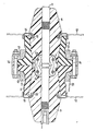
- 1 and 2 denote two conductors which are approximately aligned with one another and form a separable current path.
- the conductors 1, 2 are connected by a contact device which is designed to compensate for misalignments of the conductors 1, 2 and consists of contact lamellae 3 and ring springs 4 comprising the contact lamellae 3.
- the conductor 1 is surrounded by a rotationally symmetrical insulator 5 and the conductor 2 by a same rotationally s ymetrischen insulator 6.
- the insulators 5, 6 may, for example, consist of filler-containing thermosetting plastic.
- the two conductors 1, 2 are also kept at a distance that is not specified.
- a recess 5 a or 6 a is provided in the end face of each insulator 5, 6 adjoining the gap 7 for receiving the contact device consisting of the contact blades 3 and the ring springs 4.
- the insulators 5, 6 are each surrounded by an elastic sleeve 8 or 9 made of insulating material.
- the mutually facing end faces of the sleeves 8, 9 are pressed against each other with a clamping device which has two clamping bushes 1 0 and 11 respectively.
- the clamping bushes 1 0 , 11 each sit on an annular shoulder 12, 13 of a sleeve 8, 9 and are penetrated by clamping screws 14.
- the surfaces of the insulators 5, 6 and the sleeves 8, 9 adjoining the intermediate space 7 are electrically conductive in order to prevent glow discharges.
- the inner lateral surfaces and the pressed surfaces of the sleeves 8, 9 and the lateral surfaces of the insulators 5, 6 are each electrically conductive in the transition area to the intermediate space 7 and are in electrically conductive connection with one another and with the conductors 1, 2. Glow discharges are avoided with this arrangement.
- the insulators 5, 6 it has proven to be expedient, as shown in the drawing, to give the insulators 5, 6 the shape of two truncated cones placed one on top of the other with their larger base areas. This shape is favorable for the production, but also for the arrangement of each of the insulators 5, 6 own flange 15 or 16.
- the flanges 15, 16 are designed for fastening the insulators 5, 6 on walls 17, 18 shown in phantom.
- Each of the flanges 17, 18 engages over the free end face of the associated sleeve 8 or 9 and ends in the associated insulator 5, 6 in an elastic, electrically conductive layer 19, 2 0 , which is arranged in the respective insulator 5, 6 without gaps.
- the sleeves 8, 9 are also electrically conductive and are in an electrically conductive connection with one another and with the flanges 15 and 16.
- each clamping bush 10, 11 can be provided with a tubular extension which protects the free surface of the associated sleeve 8, 9.
Landscapes
- Engineering & Computer Science (AREA)
- Power Engineering (AREA)
- Cable Accessories (AREA)
- Insulating Bodies (AREA)
- Insulators (AREA)
- Connections Effected By Soldering, Adhesion, Or Permanent Deformation (AREA)
- Coupling Device And Connection With Printed Circuit (AREA)
- Details Of Connecting Devices For Male And Female Coupling (AREA)
- Contacts (AREA)
Applications Claiming Priority (2)
| Application Number | Priority Date | Filing Date | Title |
|---|---|---|---|
| DE8512181U | 1985-04-24 | ||
| DE8512181U DE8512181U1 (de) | 1985-04-24 | 1985-04-24 | Elektrische Verbindung |
Publications (1)
| Publication Number | Publication Date |
|---|---|
| EP0199208A1 true EP0199208A1 (fr) | 1986-10-29 |
Family
ID=6780327
Family Applications (1)
| Application Number | Title | Priority Date | Filing Date |
|---|---|---|---|
| EP86104960A Withdrawn EP0199208A1 (fr) | 1985-04-24 | 1986-04-11 | Connexion électrique |
Country Status (4)
| Country | Link |
|---|---|
| EP (1) | EP0199208A1 (fr) |
| DE (1) | DE8512181U1 (fr) |
| DK (1) | DK174986A (fr) |
| NO (1) | NO855277L (fr) |
Cited By (3)
| Publication number | Priority date | Publication date | Assignee | Title |
|---|---|---|---|---|
| EP0497248A1 (fr) * | 1991-02-01 | 1992-08-05 | Gec Alsthom Sa | Connexion électrique notamment pour poste électrique modulaire moyenne tension |
| EP1294064A3 (fr) * | 2001-09-18 | 2003-10-01 | Alstom | Contact électrique pour cellules de commutation à isolation gazeuse |
| US7473847B2 (en) | 2003-07-18 | 2009-01-06 | Ormazabal Y Cia S.A. | Coupling system between high-voltage electrical equipment |
Families Citing this family (2)
| Publication number | Priority date | Publication date | Assignee | Title |
|---|---|---|---|---|
| DE8512181U1 (de) * | 1985-04-24 | 1985-08-08 | Siemens AG, 1000 Berlin und 8000 München | Elektrische Verbindung |
| DE19615553A1 (de) * | 1996-04-19 | 1997-10-23 | Abb Patent Gmbh | Sammelschienenkupplung durch die benachbarten Wände zweier nebeneinanderstehender Schaltfelder |
Citations (7)
| Publication number | Priority date | Publication date | Assignee | Title |
|---|---|---|---|---|
| US1773713A (en) * | 1926-08-05 | 1930-08-26 | Ohio Brass Co | Joint for covered conductors |
| US1773715A (en) * | 1926-08-05 | 1930-08-26 | Ohio Brass Co | Joint for cables |
| US3513425A (en) * | 1969-05-21 | 1970-05-19 | Gen Electric | Modular electrical conductor termination system |
| FR2096734A1 (fr) * | 1970-04-27 | 1972-02-25 | Hazemeijer Co | |
| FR2141752A1 (fr) * | 1971-06-16 | 1973-01-26 | Siemens Ag | |
| US3845458A (en) * | 1972-08-22 | 1974-10-29 | Meidensha Electric Mfg Co Ltd | Bus-bar connection apparatus for an electrical machinery of metal clad type |
| DE8512181U1 (de) * | 1985-04-24 | 1985-08-08 | Siemens AG, 1000 Berlin und 8000 München | Elektrische Verbindung |
-
1985
- 1985-04-24 DE DE8512181U patent/DE8512181U1/de not_active Expired
- 1985-12-23 NO NO855277A patent/NO855277L/no unknown
-
1986
- 1986-04-11 EP EP86104960A patent/EP0199208A1/fr not_active Withdrawn
- 1986-04-17 DK DK174986A patent/DK174986A/da unknown
Patent Citations (7)
| Publication number | Priority date | Publication date | Assignee | Title |
|---|---|---|---|---|
| US1773713A (en) * | 1926-08-05 | 1930-08-26 | Ohio Brass Co | Joint for covered conductors |
| US1773715A (en) * | 1926-08-05 | 1930-08-26 | Ohio Brass Co | Joint for cables |
| US3513425A (en) * | 1969-05-21 | 1970-05-19 | Gen Electric | Modular electrical conductor termination system |
| FR2096734A1 (fr) * | 1970-04-27 | 1972-02-25 | Hazemeijer Co | |
| FR2141752A1 (fr) * | 1971-06-16 | 1973-01-26 | Siemens Ag | |
| US3845458A (en) * | 1972-08-22 | 1974-10-29 | Meidensha Electric Mfg Co Ltd | Bus-bar connection apparatus for an electrical machinery of metal clad type |
| DE8512181U1 (de) * | 1985-04-24 | 1985-08-08 | Siemens AG, 1000 Berlin und 8000 München | Elektrische Verbindung |
Cited By (6)
| Publication number | Priority date | Publication date | Assignee | Title |
|---|---|---|---|---|
| EP0497248A1 (fr) * | 1991-02-01 | 1992-08-05 | Gec Alsthom Sa | Connexion électrique notamment pour poste électrique modulaire moyenne tension |
| FR2672440A1 (fr) * | 1991-02-01 | 1992-08-07 | Alsthom Gec | Connexion electrique notamment pour poste electrique modulaire moyenne tension. |
| US5188538A (en) * | 1991-02-01 | 1993-02-23 | Gec Alsthom Sa | Electrical connection, in particular for a modular, medium-tension electricity substation |
| CN1037556C (zh) * | 1991-02-01 | 1998-02-25 | Gec阿尔斯托姆有限公司 | 主要用于中压组合式电设备的电连接装置 |
| EP1294064A3 (fr) * | 2001-09-18 | 2003-10-01 | Alstom | Contact électrique pour cellules de commutation à isolation gazeuse |
| US7473847B2 (en) | 2003-07-18 | 2009-01-06 | Ormazabal Y Cia S.A. | Coupling system between high-voltage electrical equipment |
Also Published As
| Publication number | Publication date |
|---|---|
| NO855277L (no) | 1986-10-27 |
| DK174986A (da) | 1986-10-25 |
| DK174986D0 (da) | 1986-04-17 |
| DE8512181U1 (de) | 1985-08-08 |
Similar Documents
| Publication | Publication Date | Title |
|---|---|---|
| DE3050661C2 (de) | Anordnung zur Verbindung zweier Leiterstabenden | |
| DE2656694A1 (de) | Abgriffsverbindungskasten fuer kabelfernsehen | |
| DD294376A5 (de) | Steckkupplung fuer hochspannungsplastkabel | |
| DE69516241T2 (de) | Teil einer Zündung für innere Brennkraftmaschinen und Verfahren zu seiner Herstellung | |
| DE3008953C2 (de) | Mehradriges Flachbandkabel | |
| DE2607309A1 (de) | Kabelfernsehanlage | |
| EP0199249A1 (fr) | Connexion électrique | |
| DE60302953T2 (de) | Verbinder für zwei elektrische Energiekabel und Verbindung mit einem solchen Verbinder | |
| EP0199208A1 (fr) | Connexion électrique | |
| EP0400491A2 (fr) | Dispositif d'alimentation en courant d'un dispositf d'indication pour indiquer la tension du réseau d'une installation de distribution à moyenne tension | |
| EP0692153B1 (fr) | Armature pour conducteurs de reseau d'alimentation en energie haute tension et son procede de fabrication | |
| DE3688596T2 (de) | Hochspannungsanschlussvorrichtung, insbesondere für Hochspannungstransformator. | |
| DE1465485A1 (de) | Wasserdichte Kabelkupplung | |
| DE1902057U (de) | Strahlungsgeschuetzte kunststoff- oder gummiisolierte ader fuer starkstromkabel und -leitungen. | |
| DE3041337C2 (fr) | ||
| EP0367903A2 (fr) | Pièce de connexion femelle pour la réalisation simultanée de connexions à basse et haute intensité | |
| DE3940652A1 (de) | Elektrische steckverbindung | |
| DE3037915A1 (de) | Vorrichtung zum halten und stuetzen von stromleitern, stuetzleitern, stuetzisolator und verfahren zu dessen herstellung | |
| DE19845006C1 (de) | Oberirdische Kabelverbindung | |
| DE19525801C2 (de) | Vorrichtung zum elektrisch leitenden Verbinden von zwei elektrischen Leitungen | |
| DE102017102370A1 (de) | Verbindungsmuffe | |
| DE3802435C2 (fr) | ||
| DE3247482A1 (de) | Verbindungsvorrichtung | |
| DE19702801C1 (de) | Dreiteilige aufschiebbare Verbindungsmuffe | |
| AT394121B (de) | Isolierte konus-abspannklemme |
Legal Events
| Date | Code | Title | Description |
|---|---|---|---|
| PUAI | Public reference made under article 153(3) epc to a published international application that has entered the european phase |
Free format text: ORIGINAL CODE: 0009012 |
|
| AK | Designated contracting states |
Kind code of ref document: A1 Designated state(s): CH DE FR GB LI NL |
|
| 17P | Request for examination filed |
Effective date: 19861127 |
|
| 17Q | First examination report despatched |
Effective date: 19880218 |
|
| STAA | Information on the status of an ep patent application or granted ep patent |
Free format text: STATUS: THE APPLICATION IS DEEMED TO BE WITHDRAWN |
|
| 18D | Application deemed to be withdrawn |
Effective date: 19880629 |
|
| RIN1 | Information on inventor provided before grant (corrected) |
Inventor name: POTH, RAINER |