EP0199208A1 - Electrical connection - Google Patents
Electrical connection Download PDFInfo
- Publication number
- EP0199208A1 EP0199208A1 EP86104960A EP86104960A EP0199208A1 EP 0199208 A1 EP0199208 A1 EP 0199208A1 EP 86104960 A EP86104960 A EP 86104960A EP 86104960 A EP86104960 A EP 86104960A EP 0199208 A1 EP0199208 A1 EP 0199208A1
- Authority
- EP
- European Patent Office
- Prior art keywords
- electrically conductive
- insulators
- conductors
- insulator
- sleeves
- Prior art date
- Legal status (The legal status is an assumption and is not a legal conclusion. Google has not performed a legal analysis and makes no representation as to the accuracy of the status listed.)
- Withdrawn
Links
Images
Classifications
-
- H—ELECTRICITY
- H01—ELECTRIC ELEMENTS
- H01R—ELECTRICALLY-CONDUCTIVE CONNECTIONS; STRUCTURAL ASSOCIATIONS OF A PLURALITY OF MUTUALLY-INSULATED ELECTRICAL CONNECTING ELEMENTS; COUPLING DEVICES; CURRENT COLLECTORS
- H01R13/00—Details of coupling devices of the kinds covered by groups H01R12/70 or H01R24/00 - H01R33/00
- H01R13/46—Bases; Cases
- H01R13/53—Bases or cases for heavy duty; Bases or cases for high voltage with means for preventing corona or arcing
-
- H—ELECTRICITY
- H02—GENERATION; CONVERSION OR DISTRIBUTION OF ELECTRIC POWER
- H02B—BOARDS, SUBSTATIONS OR SWITCHING ARRANGEMENTS FOR THE SUPPLY OR DISTRIBUTION OF ELECTRIC POWER
- H02B13/00—Arrangement of switchgear in which switches are enclosed in, or structurally associated with, a casing, e.g. cubicle
- H02B13/005—Electrical connection between switchgear cells
-
- H—ELECTRICITY
- H01—ELECTRIC ELEMENTS
- H01R—ELECTRICALLY-CONDUCTIVE CONNECTIONS; STRUCTURAL ASSOCIATIONS OF A PLURALITY OF MUTUALLY-INSULATED ELECTRICAL CONNECTING ELEMENTS; COUPLING DEVICES; CURRENT COLLECTORS
- H01R31/00—Coupling parts supported only by co-operation with counterpart
- H01R31/06—Intermediate parts for linking two coupling parts, e.g. adapter
Definitions
- the invention relates to an electrical connection according to the preamble of claim 1.
- the object of the invention is to provide the electrical connection according to the preamble of claim 1 with an electrical insulation having a high insulation value, in which field stresses of air gaps are prevented.
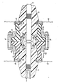
- 1 and 2 denote two conductors which are approximately aligned with one another and form a separable current path.
- the conductors 1, 2 are connected by a contact device which is designed to compensate for misalignments of the conductors 1, 2 and consists of contact lamellae 3 and ring springs 4 comprising the contact lamellae 3.
- the conductor 1 is surrounded by a rotationally symmetrical insulator 5 and the conductor 2 by a same rotationally s ymetrischen insulator 6.
- the insulators 5, 6 may, for example, consist of filler-containing thermosetting plastic.
- the two conductors 1, 2 are also kept at a distance that is not specified.
- a recess 5 a or 6 a is provided in the end face of each insulator 5, 6 adjoining the gap 7 for receiving the contact device consisting of the contact blades 3 and the ring springs 4.
- the insulators 5, 6 are each surrounded by an elastic sleeve 8 or 9 made of insulating material.
- the mutually facing end faces of the sleeves 8, 9 are pressed against each other with a clamping device which has two clamping bushes 1 0 and 11 respectively.
- the clamping bushes 1 0 , 11 each sit on an annular shoulder 12, 13 of a sleeve 8, 9 and are penetrated by clamping screws 14.
- the surfaces of the insulators 5, 6 and the sleeves 8, 9 adjoining the intermediate space 7 are electrically conductive in order to prevent glow discharges.
- the inner lateral surfaces and the pressed surfaces of the sleeves 8, 9 and the lateral surfaces of the insulators 5, 6 are each electrically conductive in the transition area to the intermediate space 7 and are in electrically conductive connection with one another and with the conductors 1, 2. Glow discharges are avoided with this arrangement.
- the insulators 5, 6 it has proven to be expedient, as shown in the drawing, to give the insulators 5, 6 the shape of two truncated cones placed one on top of the other with their larger base areas. This shape is favorable for the production, but also for the arrangement of each of the insulators 5, 6 own flange 15 or 16.
- the flanges 15, 16 are designed for fastening the insulators 5, 6 on walls 17, 18 shown in phantom.
- Each of the flanges 17, 18 engages over the free end face of the associated sleeve 8 or 9 and ends in the associated insulator 5, 6 in an elastic, electrically conductive layer 19, 2 0 , which is arranged in the respective insulator 5, 6 without gaps.
- the sleeves 8, 9 are also electrically conductive and are in an electrically conductive connection with one another and with the flanges 15 and 16.
- each clamping bush 10, 11 can be provided with a tubular extension which protects the free surface of the associated sleeve 8, 9.
Landscapes
- Engineering & Computer Science (AREA)
- Power Engineering (AREA)
- Cable Accessories (AREA)
- Insulating Bodies (AREA)
- Insulators (AREA)
- Connections Effected By Soldering, Adhesion, Or Permanent Deformation (AREA)
- Coupling Device And Connection With Printed Circuit (AREA)
- Details Of Connecting Devices For Male And Female Coupling (AREA)
- Contacts (AREA)
Abstract
Description
Die Erfindung bezieht sich auf eine elektrische Verbindung nach dem Oberbegriff des Anspruches 1.The invention relates to an electrical connection according to the preamble of claim 1.
Es ist bereits eine elektrische Verbindung der im Oberbegriff des Anspruches 1 genannten Art vorgeschlagen worden, bei der jedoch keinerleit Maßnahmen zum elektrischen Isolieren der stromführenden Teile getroffen sind.An electrical connection of the type mentioned in the preamble of claim 1 has already been proposed, but no measures have been taken for electrically isolating the live parts.
Aufgabe der Erfindung ist es, die elektrische Verbindung nach dem Oberbegriff des Anspruches 1 mit einer einen hohen Isolationswert aufweisenden elektrischen Isoaltion zu versehen, bei der Feldbeanspruchungen von Luftstrecken verhindert sind.The object of the invention is to provide the electrical connection according to the preamble of claim 1 with an electrical insulation having a high insulation value, in which field stresses of air gaps are prevented.
Die gestellte Aufgabe wird erfindungsgemäß durch die im kennzeichnenden Teil des Anspruches 1 genannte Ausbildung gelöst.The object is achieved according to the invention by the training mentioned in the characterizing part of claim 1.
Zweckmäßige Aus- und Weiterbildungen des Erfindungsgegenstandes sind in den Ansprüchen 2 bis 7 angegeben.Appropriate training and further developments of the subject matter of the invention are specified in
Ein Ausführungsbeispiel der Erfindung ist in der Zeichnung rein schematisch in einem Aufriß im Schnitt dargestellt.An embodiment of the invention is shown in the drawing purely schematically in an elevation in section.
In der Zeichnung sind mit 1 beziehungsweise 2 zwei etwa miteinander fluchtende, eine auftrennbare Strombahn bildende Leiter bezeichnet. Die Leiter 1, 2 sind durch eine Kontaktvorrichtung verbunden, die zum Ausgleichen von Fluchtabweichungen der Leiter 1, 2 ausgebildet ist und aus Kontaktlamellen 3 sowie die Kontaktlamellen 3 umfas- senden Ringfedern 4 besteht.In the drawing, 1 and 2 denote two conductors which are approximately aligned with one another and form a separable current path. The
Der Leiter 1 ist von einem rotationssymetrischen Isolator 5 umgeben und der Leiter 2 von einem gleichen rotations- symetrischen Isolator 6. Die Isolatoren 5, 6 können zum Beispiel aus Füllstoffe enthaltendem duroplastischen Kunststoff bestehen.The conductor 1 is surrounded by a rotationally symmetrical insulator 5 and the
Zum Auffangen von Fertigungstoleranzen und Wärmedehnungen besteht zwischen den beiden Isolatoren 5,6 ein Zwischenraum 7. Aus dem gleich Grund sind auch die beiden Leitern 1, 2 in einem nicht näher bezeichneten Abstand gehalten. Um den Zwischenraum 7 nicht unverhältnismäßig groß machen zu müssen, ist in der an den Zwischenraum 7 angrenzenden Stirnfläche jedes Isolators 5, 6 eine Vertiefung 5 a beziehungsweise 6 a für die Aufnahme der aus den Kontaktlamellen 3 und den Ringfedern 4 bestehenden Kontaktvorrichtung vorgesehen.To compensate for manufacturing tolerances and thermal expansions, there is a space 7 between the two
Die Isolatoren 5, 6 sind jeweils von einer aus Isolierstoff bestehenden elastischen Manschette 8, beziehungsweise 9 umgeben. Die einander zugekehrten Stirnflächen der Manschetten 8, 9 sind mit einer Spannvorrichtung gegeneinandergepreßt, die zwei Spannbuchsen 10, beziehungsweise 11 aufweist. Die Spannbuchsen 10, 11 sitzen jeweils auf einer Ringschulter 12, 13 einer Manschette 8, 9 auf und sind von Spannschrauben 14 durchsetzt.The
Die an den Zwischenraum 7 angrenzenden Flächen der Isolatoren 5, 6 und der Manschetten 8, 9 sind zur Verhinderung von Glimmentladungen elektrisch leitfähig. Die inneren Mantelflächen und die aneinandergepreßten Flächen der Manschetten 8, 9 sowie die Mantelflächen der Isolatoren 5, 6 sind jeweils im Übergangsbereich zum Zwischenraum 7 elektrisch leitfähig und stehen untereinander sowie mit den Leitern 1, 2 in elektrisch leitfähiger Verbindung. Mit dieser Anordnung sind Glimmentladungen vermieden.The surfaces of the
Es hat sich als zweckmäßig erwiesen, wie in der Zeichnung dargestellt, den Isolatoren 5, 6 jeweils die Form zweier mit ihren größeren Grundflächen aufeinander gesetzter Kegelstümpfe zu geben. Diese Form ist für die Herstellung günstig, aber auch für die Anordnung eines jedem Isolator 5, 6 eigenen Flansches 15 beziehungsweise 16. Die Flansche 15, 16 sind zur Befestigung der Isolatoren 5, 6 an strichpunktiert dargestellten Wänden 17, 18 ausgebildet.It has proven to be expedient, as shown in the drawing, to give the
Jeder der Flansche 17, 18 übergreift die freie Stirnfläche der zugeordneten Manschette 8 beziehungsweise 9 und endet im zugeordneten Isolator 5, 6 in einer elastischen, elektrisch leitfähigen Schicht 19, 20, die spaltfrei im jeweiligen Isolator 5, 6 angeordnet ist.Each of the
Um die Manschetten 8, 9 erden zu können, sind ihre äusseren Mantelflächen ebenfalls elektrisch leitfähig und stehen untereinander sowie mit den Flanschen 15 und 16 in elektrisch leitfähiger VerbLndung.In order to be able to ground the
Wie an der Spannbuchse 11 strichpunktiert dargestellt, kann jede Spannbuchse 10, 11 mit einem rohrförmigen Fortsatz versehen sein, der die freie Oberfläche der zugeordneten Manschette 8, 9 schützend verdeckt.As shown in dash-dotted lines on the clamping bush 11, each
- 1 = Leiter1 = leader
- 2 = Leiter2 = ladder
- 3 = Kontaktlamellen3 = contact blades
- 4 = Ringfedern4 = ring springs
- 5 = Isolator - 5 a = Vertiefung5 = insulator - 5 a = depression
- 6 = Isolator - 6 a = Vertiefung6 = insulator - 6 a = depression
- 7 = Zwischenraum7 = space
- 8 = Manschette8 = cuff
- 9 = Manschette9 = cuff
- 1o = Spannbuchse1o = clamping bush
- 11 = Spannbuchse11 = clamping bush
- 12 = Ringschulter12 = ring shoulder
- 13 = Ringschulter13 = ring shoulder
- 14 = Spannschrauben14 = clamping screws
- 15 = Flansch15 = flange
- 16 = Flansch16 = flange
- 17 = Wand17 = wall
- 18 = Wand18 = wall
- 19 = Schicht19 = shift
- 20 = Schicht20 = shift
- 21 = Fortsatz21 = continuation
Claims (7)
Applications Claiming Priority (2)
| Application Number | Priority Date | Filing Date | Title |
|---|---|---|---|
| DE8512181U | 1985-04-24 | ||
| DE8512181U DE8512181U1 (en) | 1985-04-24 | 1985-04-24 | Electrical connection |
Publications (1)
| Publication Number | Publication Date |
|---|---|
| EP0199208A1 true EP0199208A1 (en) | 1986-10-29 |
Family
ID=6780327
Family Applications (1)
| Application Number | Title | Priority Date | Filing Date |
|---|---|---|---|
| EP86104960A Withdrawn EP0199208A1 (en) | 1985-04-24 | 1986-04-11 | Electrical connection |
Country Status (4)
| Country | Link |
|---|---|
| EP (1) | EP0199208A1 (en) |
| DE (1) | DE8512181U1 (en) |
| DK (1) | DK174986A (en) |
| NO (1) | NO855277L (en) |
Cited By (3)
| Publication number | Priority date | Publication date | Assignee | Title |
|---|---|---|---|---|
| EP0497248A1 (en) * | 1991-02-01 | 1992-08-05 | Gec Alsthom Sa | Electrical connection especially for medium voltage modules of electrical cabinet |
| EP1294064A3 (en) * | 2001-09-18 | 2003-10-01 | Alstom | Electrical connection between gas insulated switchgear cells |
| US7473847B2 (en) | 2003-07-18 | 2009-01-06 | Ormazabal Y Cia S.A. | Coupling system between high-voltage electrical equipment |
Families Citing this family (2)
| Publication number | Priority date | Publication date | Assignee | Title |
|---|---|---|---|---|
| DE8512181U1 (en) * | 1985-04-24 | 1985-08-08 | Siemens AG, 1000 Berlin und 8000 München | Electrical connection |
| DE19615553A1 (en) * | 1996-04-19 | 1997-10-23 | Abb Patent Gmbh | Busbar coupling through the adjacent walls of two adjacent panels |
Citations (7)
| Publication number | Priority date | Publication date | Assignee | Title |
|---|---|---|---|---|
| US1773713A (en) * | 1926-08-05 | 1930-08-26 | Ohio Brass Co | Joint for covered conductors |
| US1773715A (en) * | 1926-08-05 | 1930-08-26 | Ohio Brass Co | Joint for cables |
| US3513425A (en) * | 1969-05-21 | 1970-05-19 | Gen Electric | Modular electrical conductor termination system |
| FR2096734A1 (en) * | 1970-04-27 | 1972-02-25 | Hazemeijer Co | |
| FR2141752A1 (en) * | 1971-06-16 | 1973-01-26 | Siemens Ag | |
| US3845458A (en) * | 1972-08-22 | 1974-10-29 | Meidensha Electric Mfg Co Ltd | Bus-bar connection apparatus for an electrical machinery of metal clad type |
| DE8512181U1 (en) * | 1985-04-24 | 1985-08-08 | Siemens AG, 1000 Berlin und 8000 München | Electrical connection |
-
1985
- 1985-04-24 DE DE8512181U patent/DE8512181U1/en not_active Expired
- 1985-12-23 NO NO855277A patent/NO855277L/en unknown
-
1986
- 1986-04-11 EP EP86104960A patent/EP0199208A1/en not_active Withdrawn
- 1986-04-17 DK DK174986A patent/DK174986A/en unknown
Patent Citations (7)
| Publication number | Priority date | Publication date | Assignee | Title |
|---|---|---|---|---|
| US1773713A (en) * | 1926-08-05 | 1930-08-26 | Ohio Brass Co | Joint for covered conductors |
| US1773715A (en) * | 1926-08-05 | 1930-08-26 | Ohio Brass Co | Joint for cables |
| US3513425A (en) * | 1969-05-21 | 1970-05-19 | Gen Electric | Modular electrical conductor termination system |
| FR2096734A1 (en) * | 1970-04-27 | 1972-02-25 | Hazemeijer Co | |
| FR2141752A1 (en) * | 1971-06-16 | 1973-01-26 | Siemens Ag | |
| US3845458A (en) * | 1972-08-22 | 1974-10-29 | Meidensha Electric Mfg Co Ltd | Bus-bar connection apparatus for an electrical machinery of metal clad type |
| DE8512181U1 (en) * | 1985-04-24 | 1985-08-08 | Siemens AG, 1000 Berlin und 8000 München | Electrical connection |
Cited By (6)
| Publication number | Priority date | Publication date | Assignee | Title |
|---|---|---|---|---|
| EP0497248A1 (en) * | 1991-02-01 | 1992-08-05 | Gec Alsthom Sa | Electrical connection especially for medium voltage modules of electrical cabinet |
| FR2672440A1 (en) * | 1991-02-01 | 1992-08-07 | Alsthom Gec | ELECTRICAL CONNECTION IN PARTICULAR FOR MEDIUM VOLTAGE MODULAR ELECTRICAL STATION. |
| US5188538A (en) * | 1991-02-01 | 1993-02-23 | Gec Alsthom Sa | Electrical connection, in particular for a modular, medium-tension electricity substation |
| CN1037556C (en) * | 1991-02-01 | 1998-02-25 | Gec阿尔斯托姆有限公司 | Electrical connection, in particular for modular, medium-tension electri city substation |
| EP1294064A3 (en) * | 2001-09-18 | 2003-10-01 | Alstom | Electrical connection between gas insulated switchgear cells |
| US7473847B2 (en) | 2003-07-18 | 2009-01-06 | Ormazabal Y Cia S.A. | Coupling system between high-voltage electrical equipment |
Also Published As
| Publication number | Publication date |
|---|---|
| NO855277L (en) | 1986-10-27 |
| DK174986A (en) | 1986-10-25 |
| DK174986D0 (en) | 1986-04-17 |
| DE8512181U1 (en) | 1985-08-08 |
Similar Documents
| Publication | Publication Date | Title |
|---|---|---|
| DE3050661C2 (en) | Arrangement for connecting two conductor rod ends | |
| DE2656694A1 (en) | PIPE CONNECTION BOX FOR CABLE TV | |
| DD294376A5 (en) | PLUG COUPLING FOR HIGH VOLTAGE PLUG CABLE | |
| DE69516241T2 (en) | Part of an ignition for internal combustion engines and process for its manufacture | |
| DE3008953C2 (en) | Multi-core ribbon cable | |
| DE2607309A1 (en) | CABLE TV SYSTEM | |
| EP0199249A1 (en) | Electrical connection | |
| DE60302953T2 (en) | Connector for two electrical power cables and connection with such a connector | |
| EP0199208A1 (en) | Electrical connection | |
| EP0400491A2 (en) | Power supply arrangement for indicating device for supply voltage indication of medium voltage switch gear | |
| EP0692153B1 (en) | Armature for conductors of high-voltage power supply systems and process for producing it | |
| DE3688596T2 (en) | High-voltage connection device, in particular for high-voltage transformer. | |
| DE1465485A1 (en) | Waterproof cable coupling | |
| DE1902057U (en) | RADIATION PROTECTED PLASTIC OR RUBBER INSULATED CORES FOR POWERFUL CABLES AND LINES. | |
| DE3041337C2 (en) | ||
| EP0367903A2 (en) | Female plug part for simultaneously establishing high and low current connections | |
| DE3940652A1 (en) | Electrical plug contact - comprises two interlocking plugs each having contact pin and isolation coated socket | |
| DE3037915A1 (en) | DEVICE FOR HOLDING AND SUPPORTING CURRENT LADDERS, SUPPORT LADDERS, POST INSULATOR AND METHOD FOR THE PRODUCTION THEREOF | |
| DE19845006C1 (en) | Overhead cable connector for MV electrical network cables has corresponding cable wire ends enclosed by common connector and field control body contained within outer insulator | |
| DE19525801C2 (en) | Device for the electrically conductive connection of two electrical lines | |
| DE102017102370A1 (en) | coupling sleeve | |
| DE3802435C2 (en) | ||
| DE3247482A1 (en) | Connecting device | |
| DE19702801C1 (en) | High voltage cable connecting collar with integral field control electrodes | |
| AT394121B (en) | Insulated conical anchor clamp |
Legal Events
| Date | Code | Title | Description |
|---|---|---|---|
| PUAI | Public reference made under article 153(3) epc to a published international application that has entered the european phase |
Free format text: ORIGINAL CODE: 0009012 |
|
| AK | Designated contracting states |
Kind code of ref document: A1 Designated state(s): CH DE FR GB LI NL |
|
| 17P | Request for examination filed |
Effective date: 19861127 |
|
| 17Q | First examination report despatched |
Effective date: 19880218 |
|
| STAA | Information on the status of an ep patent application or granted ep patent |
Free format text: STATUS: THE APPLICATION IS DEEMED TO BE WITHDRAWN |
|
| 18D | Application deemed to be withdrawn |
Effective date: 19880629 |
|
| RIN1 | Information on inventor provided before grant (corrected) |
Inventor name: POTH, RAINER |