EP0198112B1 - Palier de butée pour organes de propulsion de trépans des outils de forage de puits - Google Patents
Palier de butée pour organes de propulsion de trépans des outils de forage de puits Download PDFInfo
- Publication number
- EP0198112B1 EP0198112B1 EP85112642A EP85112642A EP0198112B1 EP 0198112 B1 EP0198112 B1 EP 0198112B1 EP 85112642 A EP85112642 A EP 85112642A EP 85112642 A EP85112642 A EP 85112642A EP 0198112 B1 EP0198112 B1 EP 0198112B1
- Authority
- EP
- European Patent Office
- Prior art keywords
- bearing
- ring
- bending
- direct bit
- supporting ring
- Prior art date
- Legal status (The legal status is an assumption and is not a legal conclusion. Google has not performed a legal analysis and makes no representation as to the accuracy of the status listed.)
- Expired
Links
- 238000005553 drilling Methods 0.000 title claims description 8
- 238000005452 bending Methods 0.000 claims description 19
- 230000001050 lubricating effect Effects 0.000 claims description 6
- 239000000463 material Substances 0.000 claims description 3
- 229910003460 diamond Inorganic materials 0.000 claims description 2
- 239000010432 diamond Substances 0.000 claims description 2
- 239000000843 powder Substances 0.000 claims description 2
- 239000012530 fluid Substances 0.000 claims 3
- 229910010293 ceramic material Inorganic materials 0.000 claims 1
- UONOETXJSWQNOL-UHFFFAOYSA-N tungsten carbide Chemical compound [W+]#[C-] UONOETXJSWQNOL-UHFFFAOYSA-N 0.000 claims 1
- 239000007788 liquid Substances 0.000 description 7
- 238000011010 flushing procedure Methods 0.000 description 5
- 239000000314 lubricant Substances 0.000 description 4
- 238000005461 lubrication Methods 0.000 description 4
- 230000015572 biosynthetic process Effects 0.000 description 3
- 239000000853 adhesive Substances 0.000 description 1
- 230000001070 adhesive effect Effects 0.000 description 1
- 239000000919 ceramic Substances 0.000 description 1
- 238000001816 cooling Methods 0.000 description 1
- 239000002184 metal Substances 0.000 description 1
- 238000000926 separation method Methods 0.000 description 1
- 230000000087 stabilizing effect Effects 0.000 description 1
- 230000007704 transition Effects 0.000 description 1
Images

Classifications
-
- E—FIXED CONSTRUCTIONS
- E21—EARTH OR ROCK DRILLING; MINING
- E21B—EARTH OR ROCK DRILLING; OBTAINING OIL, GAS, WATER, SOLUBLE OR MELTABLE MATERIALS OR A SLURRY OF MINERALS FROM WELLS
- E21B4/00—Drives for drilling, used in the borehole
- E21B4/003—Bearing, sealing, lubricating details
-
- F—MECHANICAL ENGINEERING; LIGHTING; HEATING; WEAPONS; BLASTING
- F16—ENGINEERING ELEMENTS AND UNITS; GENERAL MEASURES FOR PRODUCING AND MAINTAINING EFFECTIVE FUNCTIONING OF MACHINES OR INSTALLATIONS; THERMAL INSULATION IN GENERAL
- F16C—SHAFTS; FLEXIBLE SHAFTS; ELEMENTS OR CRANKSHAFT MECHANISMS; ROTARY BODIES OTHER THAN GEARING ELEMENTS; BEARINGS
- F16C17/00—Sliding-contact bearings for exclusively rotary movement
- F16C17/04—Sliding-contact bearings for exclusively rotary movement for axial load only
- F16C17/06—Sliding-contact bearings for exclusively rotary movement for axial load only with tiltably-supported segments, e.g. Michell bearings
-
- F—MECHANICAL ENGINEERING; LIGHTING; HEATING; WEAPONS; BLASTING
- F16—ENGINEERING ELEMENTS AND UNITS; GENERAL MEASURES FOR PRODUCING AND MAINTAINING EFFECTIVE FUNCTIONING OF MACHINES OR INSTALLATIONS; THERMAL INSULATION IN GENERAL
- F16C—SHAFTS; FLEXIBLE SHAFTS; ELEMENTS OR CRANKSHAFT MECHANISMS; ROTARY BODIES OTHER THAN GEARING ELEMENTS; BEARINGS
- F16C2352/00—Apparatus for drilling
Definitions
- the invention relates to a direct chisel drive for deep drilling tools according to the preamble of patent claim 1.
- tilting segment bearings US-A-2424028
- a tilting axis which is defined by a bending web perpendicular to the bearing plane and radially oriented.
- This bending web can be arranged in the middle or somewhat off-center to the support plate of each bearing segment, but is always located below the bearing surface of the bearing segment with the result that a downward movement of the front edge of the bearing segment with respect to the direction of rotation with an upward movement of the rear edges of the bearing segments.
- the axial forces that occur in the bearing therefore counteract the formation of converging lubrication gaps.
- the invention has for its object to provide a direct chisel drive with an axial bearing, which favors the formation of converging lubricating gaps in the direction of rotation between the bearing surfaces of the bearing segments and the bearing rings.
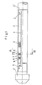
- the direct chisel drive shown in FIG. Comprises a tubular housing 1 which can be connected to a drill string 2 ′ via a thread 2.
- a rotary machine Arranged in the interior of the housing 1 is a rotary machine which can be driven by flushing liquid flowing through it, in the form of a turbine 3, the shaft 4 of which emerges axially from the bottom of the housing 1 and has a thread 5 for connection to a rotary drill bit 1 '.
- An axial bearing 6 with two support rings 7 and 8, of which one 7 is supported in the housing 1 and the other 8 on the shaft 4, is used to absorb the axial forces acting on the shaft bottom towards the bottom of the borehole.
- a further axial bearing 9 with a mirror-image arrangement of the support rings 7, 8 is provided.
- the structure of the support ring 7 supported in the housing 1 can be seen from the section through the axial bearing 6 shown in FIG.
- This has axially extending openings 10 with an approximately U-shaped or trapezoidal cross section distributed over its circumference.
- a bending beam 11 is formed integrally from the support ring 7.
- a separate bending beam 11 ' is connected to the web 12 remaining between two adjacent openings 10 in such a way that its free end 13 projects into the opening 10.
- Each bending beam 11; 11 ′ carries a bearing segment 14, which is similar but reduced in plan view to the approximately trapezoidal cross section of the openings 10 and is made of a hard, wear-resistant material, e.g. B.
- the bearing segment 14 is with its bending beam 11; 11 'by an eccentric in relation to its spatial dimensions in the circumferential direction, in the region of the transition of the bending beam 11; 11 'in the web 12 lying in the radial direction pivot axis 15 is pivotally mounted.
- the bearing segments 14 are aligned parallel to the plane of the support ring 7 in the unloaded state when the shaft 4 is stationary. With their bearing surface 16, the bearing segments 14 lie flat against the bearing surface 17 of a bearing ring 18 which is arranged on the support ring 8.
- the bearing ring 18 is preferably made of a material similar to the bearing segments 14.
- FIG. 5 While the bending beams 11 are relatively stable in FIG. 4 in order to be able to withstand even high axial forces without damage, the modified embodiment shown in FIG. 5 manages with bending beams 11 that are designed to be less stable.
- a stop ring 22 is arranged to limit its deflection at a distance from the permissible deflection path. In the position shown, the edges of the free ends 13 of the bending beams 11 rest against this stop ring 22.
- FIGS. 4 and 5 the designs as shown in FIGS. 4 and 5 are shown in half-sided longitudinal section in a plane running along the axis 23 of the bearing.
- the support ring 7 is clamped in Fig. 6 between mounting sleeves 25, which in turn are clamped between shoulders of the housing 1, not shown.
- the stop ring 22 is additionally attached to the support ring 7 and clamped together with the latter between the mounting sleeves 25.
- the support ring 8 with the bearing ring 18 is clamped between a shoulder of the shaft 4 and a mounting sleeve 26.
- an annular space 24 is left between the support ring 8 and the mounting sleeves 25.
- the flushing liquid 7 can flow through the openings 10 mentioned above, the corresponding openings 27 being arranged as extensions of the flow path in the stop ring 22, which are preferably aligned with the openings 10.
Landscapes
- Engineering & Computer Science (AREA)
- General Engineering & Computer Science (AREA)
- Mechanical Engineering (AREA)
- Life Sciences & Earth Sciences (AREA)
- Geology (AREA)
- Mining & Mineral Resources (AREA)
- Physics & Mathematics (AREA)
- Environmental & Geological Engineering (AREA)
- Fluid Mechanics (AREA)
- General Life Sciences & Earth Sciences (AREA)
- Geochemistry & Mineralogy (AREA)
- Sliding-Contact Bearings (AREA)
Claims (6)
Applications Claiming Priority (2)
| Application Number | Priority Date | Filing Date | Title |
|---|---|---|---|
| DE3513124A DE3513124C1 (de) | 1985-04-12 | 1985-04-12 | Meisseldirektantrieb fuer Tiefbohrwerkzeuge |
| DE3513124 | 1985-04-12 |
Publications (2)
| Publication Number | Publication Date |
|---|---|
| EP0198112A1 EP0198112A1 (fr) | 1986-10-22 |
| EP0198112B1 true EP0198112B1 (fr) | 1989-08-16 |
Family
ID=6267817
Family Applications (1)
| Application Number | Title | Priority Date | Filing Date |
|---|---|---|---|
| EP85112642A Expired EP0198112B1 (fr) | 1985-04-12 | 1985-10-05 | Palier de butée pour organes de propulsion de trépans des outils de forage de puits |
Country Status (4)
| Country | Link |
|---|---|
| US (1) | US4629013A (fr) |
| EP (1) | EP0198112B1 (fr) |
| CA (1) | CA1241635A (fr) |
| DE (1) | DE3513124C1 (fr) |
Families Citing this family (9)
| Publication number | Priority date | Publication date | Assignee | Title |
|---|---|---|---|---|
| DE3709836C1 (de) * | 1987-03-25 | 1988-09-29 | Eastman Christensen Co | Gleitlager fuer Tiefbohrwerkzeuge |
| DE3709838C1 (de) * | 1987-03-25 | 1988-09-29 | Eastman Christensen Co | Meisseldirektantrieb fuer Tiefbohrwerkzeuge |
| DE3709840C1 (de) * | 1987-03-25 | 1988-09-29 | Eastman Christensen Co | Meisseldirektantrieb fuer Tiefbohrwerkzeuge |
| ZA937867B (en) * | 1992-10-28 | 1994-05-20 | Csir | Diamond bearing assembly |
| ZA937866B (en) * | 1992-10-28 | 1994-05-20 | Csir | Diamond bearing assembly |
| US5480233A (en) * | 1994-10-14 | 1996-01-02 | Cunningham; James K. | Thrust bearing for use in downhole drilling systems |
| RU2186922C2 (ru) * | 2000-06-23 | 2002-08-10 | Общество с ограниченной ответственностью "ТюменНИИгипрогаз" | Опора забойного двигателя |
| USD567267S1 (en) * | 2007-03-26 | 2008-04-22 | Minor Rodger D | Rotary flaring tool |
| US8277124B2 (en) | 2009-02-27 | 2012-10-02 | Us Synthetic Corporation | Bearing apparatuses, systems including same, and related methods |
Family Cites Families (13)
| Publication number | Priority date | Publication date | Assignee | Title |
|---|---|---|---|---|
| US1991461A (en) * | 1932-10-10 | 1935-02-19 | Kingsbury Machine Works Inc | Bearing |
| US2424028A (en) * | 1943-07-01 | 1947-07-15 | Worthington Pump & Mach Corp | Bearing |
| US2577798A (en) * | 1947-05-23 | 1951-12-11 | Allis Chalmers Mfg Co | Bearing construction with segmental shoes on flexible resilient supports |
| US2874007A (en) * | 1954-07-01 | 1959-02-17 | Westinghouse Electric Corp | Bearings |
| US2890916A (en) * | 1956-04-02 | 1959-06-16 | Smith Corp A O | Thrust bearing |
| DE1084665B (de) * | 1957-03-01 | 1960-07-07 | Roger Francois Rouviere | Tiefbohrmotor, insbesondere Bohrturbine, mit von der Umlauffluessigkeit bespuelten Axialdruck-Kammlagern |
| GB882326A (en) * | 1957-03-01 | 1961-11-15 | Wladimar Tiraspolsky | Improvements in drilling motors for subterranean work comprising axial irrigated thrust bearings |
| US2983481A (en) * | 1957-03-01 | 1961-05-09 | Tiraspolsky Wladimir | Motors for subterranean drilling |
| US2991837A (en) * | 1957-05-29 | 1961-07-11 | California Research Corp | Turbo drill thrust bearings |
| FR2157206A5 (fr) * | 1971-10-15 | 1973-06-01 | Alsthom | |
| GB1392245A (en) * | 1971-11-12 | 1975-04-30 | Schwermasch Liebknecht Veb K | Axial sliding bearings |
| US3930691A (en) * | 1974-04-12 | 1976-01-06 | Jerome Greene | Swing pad bearing |
| US4453604A (en) * | 1981-03-27 | 1984-06-12 | Ioanesian Jury R | Turbodrills |
-
1985
- 1985-04-12 DE DE3513124A patent/DE3513124C1/de not_active Expired
- 1985-06-10 US US06/742,686 patent/US4629013A/en not_active Expired - Fee Related
- 1985-10-05 EP EP85112642A patent/EP0198112B1/fr not_active Expired
- 1985-10-17 CA CA000493213A patent/CA1241635A/fr not_active Expired
Also Published As
| Publication number | Publication date |
|---|---|
| US4629013A (en) | 1986-12-16 |
| CA1241635A (fr) | 1988-09-06 |
| EP0198112A1 (fr) | 1986-10-22 |
| DE3513124C1 (de) | 1986-02-06 |
Similar Documents
| Publication | Publication Date | Title |
|---|---|---|
| DE69807398T2 (de) | Drehbohrmeissel | |
| DE69007079T2 (de) | Buchse für Ölfilmlager. | |
| DE69531431T2 (de) | Drehbohrmeissel | |
| EP0198112B1 (fr) | Palier de butée pour organes de propulsion de trépans des outils de forage de puits | |
| DE3709838C1 (de) | Meisseldirektantrieb fuer Tiefbohrwerkzeuge | |
| DE3433360A1 (de) | Drosselungssystem fuer fluessigkeitsstroemung in einem absenkmotor | |
| DE3805862C2 (fr) | ||
| DE3942612A1 (de) | Offenend-spinnvorrichtung | |
| DE3900729A1 (de) | Drehanoden-roentgenroehre mit einem gleitlager, insbesondere einem spiralrillenlager | |
| DE2743825C2 (de) | Rollenmeißel | |
| DE69200838T2 (de) | Selbstpositionierende durchbiegungseinstellwalze. | |
| DE2653866A1 (de) | Kolben fuer eine hydrostatische kolbenmaschine | |
| DE3709840C1 (de) | Meisseldirektantrieb fuer Tiefbohrwerkzeuge | |
| DE1757208A1 (de) | Kreiselbrecher von der Art mit Armkreuz | |
| DE2209345C3 (de) | Vorrichtung zum Schmieren und Kühlen eines Lagers | |
| WO1997034070A9 (fr) | Dispositif de forage d'un trou de sonde | |
| DE2832903C2 (de) | Rührwerksmühle - Lager | |
| DE2801363C2 (fr) | ||
| DE2701799C2 (de) | Mischer | |
| DE10017669A1 (de) | Gasgeschmierte Gleitringdichtung | |
| DE2649524C2 (de) | Teleskopartige Vorrichtung | |
| DE102019134040A1 (de) | Reinigungsvorrichtung | |
| DE2756964C2 (de) | Rollenmeißel mit mehreren Schneidrollen | |
| DE3206614A1 (de) | Vorrichtung zum zentrieren eines bohrstranges in einem bohrloch | |
| DE4202961C2 (de) | Meißelhalterung |
Legal Events
| Date | Code | Title | Description |
|---|---|---|---|
| PUAI | Public reference made under article 153(3) epc to a published international application that has entered the european phase |
Free format text: ORIGINAL CODE: 0009012 |
|
| AK | Designated contracting states |
Kind code of ref document: A1 Designated state(s): BE FR GB |
|
| 17P | Request for examination filed |
Effective date: 19870205 |
|
| 17Q | First examination report despatched |
Effective date: 19880115 |
|
| RAP1 | Party data changed (applicant data changed or rights of an application transferred) |
Owner name: EASTMAN CHRISTENSEN COMPANY |
|
| GRAA | (expected) grant |
Free format text: ORIGINAL CODE: 0009210 |
|
| AK | Designated contracting states |
Kind code of ref document: B1 Designated state(s): BE FR GB |
|
| GBT | Gb: translation of ep patent filed (gb section 77(6)(a)/1977) | ||
| ET | Fr: translation filed | ||
| PLBE | No opposition filed within time limit |
Free format text: ORIGINAL CODE: 0009261 |
|
| STAA | Information on the status of an ep patent application or granted ep patent |
Free format text: STATUS: NO OPPOSITION FILED WITHIN TIME LIMIT |
|
| 26N | No opposition filed | ||
| PGFP | Annual fee paid to national office [announced via postgrant information from national office to epo] |
Ref country code: FR Payment date: 19940916 Year of fee payment: 10 |
|
| PGFP | Annual fee paid to national office [announced via postgrant information from national office to epo] |
Ref country code: GB Payment date: 19940927 Year of fee payment: 10 |
|
| PGFP | Annual fee paid to national office [announced via postgrant information from national office to epo] |
Ref country code: BE Payment date: 19940929 Year of fee payment: 10 |
|
| PG25 | Lapsed in a contracting state [announced via postgrant information from national office to epo] |
Ref country code: GB Effective date: 19951005 |
|
| PG25 | Lapsed in a contracting state [announced via postgrant information from national office to epo] |
Ref country code: BE Effective date: 19951031 |
|
| BERE | Be: lapsed |
Owner name: EASTMAN CHRISTENSEN CY Effective date: 19951031 |
|
| GBPC | Gb: european patent ceased through non-payment of renewal fee |
Effective date: 19951005 |
|
| PG25 | Lapsed in a contracting state [announced via postgrant information from national office to epo] |
Ref country code: FR Effective date: 19960628 |
|
| REG | Reference to a national code |
Ref country code: FR Ref legal event code: ST |