EP0197637B1 - Elektrische Prüfspitze mit Anschlussstecker - Google Patents
Elektrische Prüfspitze mit Anschlussstecker Download PDFInfo
- Publication number
- EP0197637B1 EP0197637B1 EP86301121A EP86301121A EP0197637B1 EP 0197637 B1 EP0197637 B1 EP 0197637B1 EP 86301121 A EP86301121 A EP 86301121A EP 86301121 A EP86301121 A EP 86301121A EP 0197637 B1 EP0197637 B1 EP 0197637B1
- Authority
- EP
- European Patent Office
- Prior art keywords
- tube
- plunger
- electrical
- socket
- wand
- Prior art date
- Legal status (The legal status is an assumption and is not a legal conclusion. Google has not performed a legal analysis and makes no representation as to the accuracy of the status listed.)
- Expired - Lifetime
Links
- 239000000523 sample Substances 0.000 title claims abstract description 44
- 238000012360 testing method Methods 0.000 title claims abstract description 30
- 239000004020 conductor Substances 0.000 claims description 26
- 230000006835 compression Effects 0.000 claims description 4
- 238000007906 compression Methods 0.000 claims description 4
- 238000003780 insertion Methods 0.000 description 5
- 230000037431 insertion Effects 0.000 description 5
- 238000009413 insulation Methods 0.000 description 3
- 229910001020 Au alloy Inorganic materials 0.000 description 2
- PXHVJJICTQNCMI-UHFFFAOYSA-N Nickel Chemical compound [Ni] PXHVJJICTQNCMI-UHFFFAOYSA-N 0.000 description 2
- DMFGNRRURHSENX-UHFFFAOYSA-N beryllium copper Chemical compound [Be].[Cu] DMFGNRRURHSENX-UHFFFAOYSA-N 0.000 description 2
- 238000010276 construction Methods 0.000 description 2
- 239000003353 gold alloy Substances 0.000 description 2
- 238000004519 manufacturing process Methods 0.000 description 2
- 238000000034 method Methods 0.000 description 2
- 229910001316 Ag alloy Inorganic materials 0.000 description 1
- 229910001369 Brass Inorganic materials 0.000 description 1
- 229910000881 Cu alloy Inorganic materials 0.000 description 1
- 239000010951 brass Substances 0.000 description 1
- 238000004891 communication Methods 0.000 description 1
- 238000002788 crimping Methods 0.000 description 1
- 238000013461 design Methods 0.000 description 1
- 239000012777 electrically insulating material Substances 0.000 description 1
- 238000005516 engineering process Methods 0.000 description 1
- PCHJSUWPFVWCPO-UHFFFAOYSA-N gold Chemical compound [Au] PCHJSUWPFVWCPO-UHFFFAOYSA-N 0.000 description 1
- 229910052737 gold Inorganic materials 0.000 description 1
- 239000010931 gold Substances 0.000 description 1
- 238000007373 indentation Methods 0.000 description 1
- 230000003993 interaction Effects 0.000 description 1
- 239000000463 material Substances 0.000 description 1
- 229910052751 metal Inorganic materials 0.000 description 1
- 239000002184 metal Substances 0.000 description 1
- 229910052759 nickel Inorganic materials 0.000 description 1
- MOFOBJHOKRNACT-UHFFFAOYSA-N nickel silver Chemical compound [Ni].[Ag] MOFOBJHOKRNACT-UHFFFAOYSA-N 0.000 description 1
- 239000010956 nickel silver Substances 0.000 description 1
- 239000010970 precious metal Substances 0.000 description 1
- 238000003825 pressing Methods 0.000 description 1
- 238000000926 separation method Methods 0.000 description 1
- 238000004513 sizing Methods 0.000 description 1
- 238000010618 wire wrap Methods 0.000 description 1
Images


Classifications
-
- H—ELECTRICITY
- H01—ELECTRIC ELEMENTS
- H01R—ELECTRICALLY-CONDUCTIVE CONNECTIONS; STRUCTURAL ASSOCIATIONS OF A PLURALITY OF MUTUALLY-INSULATED ELECTRICAL CONNECTING ELEMENTS; COUPLING DEVICES; CURRENT COLLECTORS
- H01R11/00—Individual connecting elements providing two or more spaced connecting locations for conductive members which are, or may be, thereby interconnected, e.g. end pieces for wires or cables supported by the wire or cable and having means for facilitating electrical connection to some other wire, terminal, or conductive member, blocks of binding posts
- H01R11/11—End pieces or tapping pieces for wires, supported by the wire and for facilitating electrical connection to some other wire, terminal or conductive member
- H01R11/18—End pieces terminating in a probe
-
- G—PHYSICS
- G01—MEASURING; TESTING
- G01R—MEASURING ELECTRIC VARIABLES; MEASURING MAGNETIC VARIABLES
- G01R1/00—Details of instruments or arrangements of the types included in groups G01R5/00 - G01R13/00 and G01R31/00
- G01R1/02—General constructional details
- G01R1/04—Housings; Supporting members; Arrangements of terminals
- G01R1/0408—Test fixtures or contact fields; Connectors or connecting adaptors; Test clips; Test sockets
- G01R1/0416—Connectors, terminals
-
- G—PHYSICS
- G01—MEASURING; TESTING
- G01R—MEASURING ELECTRIC VARIABLES; MEASURING MAGNETIC VARIABLES
- G01R1/00—Details of instruments or arrangements of the types included in groups G01R5/00 - G01R13/00 and G01R31/00
- G01R1/02—General constructional details
- G01R1/06—Measuring leads; Measuring probes
- G01R1/067—Measuring probes
- G01R1/06705—Apparatus for holding or moving single probes
-
- G—PHYSICS
- G01—MEASURING; TESTING
- G01R—MEASURING ELECTRIC VARIABLES; MEASURING MAGNETIC VARIABLES
- G01R1/00—Details of instruments or arrangements of the types included in groups G01R5/00 - G01R13/00 and G01R31/00
- G01R1/02—General constructional details
- G01R1/06—Measuring leads; Measuring probes
- G01R1/067—Measuring probes
- G01R1/06711—Probe needles; Cantilever beams; "Bump" contacts; Replaceable probe pins
- G01R1/06716—Elastic
- G01R1/06722—Spring-loaded
Definitions
- the present invention relates to electrical circuit test probes and electrical connectors therefor and, more particularly, to an electrical circuit test probe with a spring loaded plunger in a socket tube having an offset wand extending therefrom to contact the interior of a member disposed within the socket tube and wherein the socket tube is provided with a releasable connector for a conductor comprising a plug housing formed in the end of the socket tube and a collet jawed plug for gripping the electrical conductor and slidably fitting within the plug housing to grip the conductor and hold it therein in electrical contact.
- circuit testing has made rapid strides in its technology in the past few years. Until the advent of miniaturization, circuit testing, took the form shown in Figure 1. To test whether a large fuse 10 was electrically conductive, a pair of large, hand-held probes 12 connected to a meter 14 were placed across the fuse 10.
- PC printed circuit
- Fig. 2 Modern printed circuit (PC) boards have made such hand testing virtually impossible. Literally hundreds of connections at close-spaced proximity must be tested to verify proper circuit continuity. To do this in an automated way, apparatus such as that shown in Fig. 2 has come into common usage.
- the PC board 16 is positioned on a holding table 18 and a fixture 20 having a plurality of electrical test probes 22 is brought into contact with the surface thereof.
- the probes 22 are connected by cable 24 to testing logic 26. In this manner, the testing logic 26 can quickly and accurately test a multitude of circuit interconnections for proper continuity.
- the functioning of the probes 22 relative to the fixture 20 and their electrical connection to the testing logic 26 are critical to the successful operation of the testing apparatus. Any failure of the probe 22 to make effective electrical contact with the PC board 16 or any failure of the electrical contact so made to be effectively passed back to the testing logic 26 will be interpreted, wrongfully, by the testing logic 26 as a failure of the PC board 16.
- the probes 22 must have a degree of linear axial movement within the fixture 20 to accommodate variations in projection of contact points from the PC board, thereby to prevent undue pressure on the PC board 16 and/or breakage of the probe 22 while ensuring adequate electrical contact.
- a probe is shown according to U.S. Patent No. 4,200,351.
- the probe generally indicated as 28, comprises a spring-metal tube 30 press-fit within bore 32 of fixture 20.
- Probe 28 has a first cylindrical portion 34 adapted to slidably fit within the tube 30 and having a head 36 on the outer end thereof for contacting the PC board 16.
- a smaller diameter cylindrical shaft 38 extends from the cylindrical portion 34 in axial alignment therewith to pass through the bore 32 and terminate in an end 40 having a square cross-section particularly adapted for attachment of an electrical conductor thereto by a so-called Wire Wrap process.
- An enlarged portion 42 on the shaft 38 contacts the outer ends of fingers 44 formed into the tube 30 to prevent longitudinal movement out of the tube 30 of the head 36 beyond a pre-established maximum point.
- a spring 46 is under compression between shoulder 48 and the inside of the fingers 44 to bias the assembly to its outer position. Since the electrical connection to the probe (not shown) is directly attached to the end 40, there is no danger of loss of electrical continuity as the probe 28 is moved in and out of bore 32. On the negative side, should it be desired to reconfigure the probe 28 or replace it, the task is not a simple one.
- Probe 50 comprises a socket tube 52 which is slid into a pair of aligned bores 32 in the fixture 20. Electrical connection is provided to the tube 52 by pressing the electrical conductor 54 into a pair of jaws 56 in connector member 58, which is crimped into the one end of the socket tube 52.
- a tubular sleeve 60 is fitted into the end of the socket tube 52 adjacent the connector member 58.
- the head 36 is mounted on a shaft 62 having a cylindrical portion 64 sized to slidably fit within the tube 52.
- the inner end of the shaft 62 is sized to slidably fit within the tubular sleeve 60.
- Spring 46 is disposed between the tubular sleeve 60 and the cylindrical portion 64 to provide the outward biasing force on the head 36.
- Stop member 66 is provided to prevent the shaft 62 from moving outward past its previously selected maximum point.
- the socket tube 52 can be easily removed from the bores 32 as necessary. To release the electrical conductor 54, however, it must be pried from between the jaws 56. Electrical contact between the moving shaft 62 and the electrical conductor 54 is hoped for by contact between the cylindrical portion 64 and the inside of the socket tube 52 in combination with contact between the inner end of the shaft 62 and the inside of the tubular sleeve 60.
- a probe generally indicated as 68, is shown according to the teachings of U.S. Patent No. 4,461,993.
- a tube 70 is mounted within the bore 32 of fixture 20.
- the head 36 comprises the end of a cylindrical shaft 72 slidably mounted within a tube 74 having its opposite end 76 of a reduced diameter adapted to snugly fit within the tube 70.
- the electrical conductor (not shown) is electrically connected to the tube 70 in any manner desired and electrical connection is made between the tubes 70, 74 by their snug fit together in electrical contact.
- Shaft 72 has a reduced diameter portion 78 and a bulbous end 80.
- the tube 74 is crimped as at 82 to prevent the shaft 72 from moving out of tube 74 beyond its desired extension limit.
- a spring 46 is positioned within the tube 74 between the portion 78 and the bulbous end 80 to urge the head 36 to its extended position. While tube 74 and its assembled components can be easily removed from the tube 70 without disconnection of the electrical conductor (not shown), once again, electrical connection between the tube 74 and shaft 72 is hoped for by the sliding contact of the shaft 72 on the inside of tube 74, sliding contact of the bulbous end 80 within tube 74, and electrical contact by the spring 46 between the tube 74 and end 80.
- Figs. 6-8 are variations that can be applied to the embodiments of Figs. 4 and 5 in an attempt to provide a greater probability that electrical contact will be provided between the outer tube and the shaft sliding therein containing the head 36.
- Fig. 6 corresponds to the teaching from U.S. Patent No. 4,050,762.
- a spring member 82 having fingers 84 is mounted to the end of the moving shaft 86 to press against the inside walls of the tube 88.
- Fig. 7 shows the teachings of U.S. Patent 3 753 103, wherein a contact member 90 is connected to the end of sliding shaft 92 by a leaf spring 94 providing a biasing couple tending to urge the contact member 90 against the inside walls of the tube 96.
- Fig. 8 which corresponds to U.S. Patent No. 4 397 519, the inner end 98 of shaft 100 is angled at surface 102 and the biasing force of the spring 46 is applied through a ball 104 against angled surface 102 which results in a biasing force vector from spring 46 also being provided against end 98 towards the inner side wall of the tube 105.
- an electrical circuit test probe for mounting in a mounting hole in a test fixture board having a cylindrical socket tube of an electrically conductive material sized to snugly fit within the mounting hole of the fixture board, said socket tube including means for electrically connecting to an electrical conductor on one end, and being open on its opposite end; a longitudinal plunger member of an electrically conductive material having inner and outer ends and a first cylindrical portion slide fitted into said open opposite end and terminating on said outer end in an electrical contact for contacting circuits to be tested, said inner end of said first cylindrical portion being disposed within said socket tube and having a second cylindrical portion extending therefrom along a common longitudinal axis and being of a smaller diameter to form a shoulder where said two cylindrical portions join one another, a cylindrical plunger tube of an electrically conductive material disposed within said socket tube and in electrical contact therewith adjacent said electrical connecting means and a compression spring disposed between said shoulder and said plunger tube to create a bias force on said plunger member towards its extended position, characterized by said inner end of said
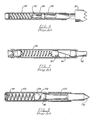
- Figs. 9-11 show a conductive metallic collet member, generally indicated as 106 adapted to fit over the end of an electrical conductor in a manner to be described shortly.
- Collet member 106 is generally cylindrical in shape and has an opening 108 into which the electrical conductor 110 can be inserted in the manner shown in Fig. 13.
- the insulation 112 is stripped from the end of the conductor 110 exposing a portion 114 of the conducting wire contained therein.
- the collet member 106 has a first cylindrical portion 116 having an internal diameter adapted to fit about the insulation 112 and a second cylindrical portion 118 of a smaller diameter adapted to fit about the conducting wire 114.
- the two portions 116, 118 form a shoulder 120 at their point of junction, which prevents insertion of the conductor 110 past its optimal point.
- the ends of the second cylindrical portion 118 are slit at 122 and curved inwardly to form two facing jaws at 124.
- Each jaw 124 has a neck portion 125 connecting it to the remainder of the cylindrical portion.
- the generally cylindrical collet member 106 has parallel diametrically opposite flat surfaces 126 formed in the region of and normal to slits 122 to reduce the thickness of material in the collet 106 laterally of the jaws 124.
- the collet member 106 is of brass tubing per CDA 330, being three-quarter hard.
- a pair of raised ridges 127 are provided circumferentially about the exterior of the collet member 106 in spaced relationship to form a groove 128 adjacent the end with the opening 108. The purpose thereof will be discussed shortly.
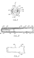
- Plug housing 130 is of nickel silver per CDA 752 with its internal surface clad with gold alloy and is comprised of a first cylindrical portion 132 into which the collet member 106 can be inserted in a sliding fit as shown in Fig. 13.
- Plug housing 130 further comprises a second cylindrical portion 134 of a smaller diameter with the two portions 132, 134 being interconnected by a tapered portion 136 smoothly tapering as shown by the angle at 138 between the portions 132, 134.
- the plug housing 130 past the second cylindrical portion 134 constricts to a closed end 140 of yet a smaller diameter and forming a shoulder 142 on the exterior where end 140 meets cylindrical portion 134.
- the end 140 is provided to allow the plug housing 130 to be mounted in the outer end of an electrical circuit test probe of the present invention, to be described shortly. As will be recognized by those skilled in the art, all that is required is that the plug housing 130 be provided with some means for electrically connecting it to the circuit to which it is going to provide releasable electrical access.
- Fig. 13 it can be seen that in use, the stripped electrical conductor 110 is inserted into the open end 108 of the collet member 106 with the insulation 112 abutting against shoulder 120 and the conducting wire 114 passing between the facing jaws 124.
- a heat shrinkable cylindrical member 144 of electrically insulating material is disposed around the member 106 between the raised ridges 127 and shrunk into the groove 128 to thereby grip the groove.
- Member 144 has an outer diameter greater than the outer diameter of the probe and connector thereby to provide electrical separation between adjacent probes in a test fixture.
- the jaws 124 of the collet member 106 are inserted into the plug housing 130 as shown in Fig.
- the jaws 124 are slid along the tapering portion 136 and into the reduced diameter second cylindrical portion 134. In so doing the jaws are forced to bite into wire 114 to produce electrically conductive gripping communication therewith with further insertion causing the necked portions 125 to be stressed sufficiently for them to plastically deform to maintain the facing jaws 124 in intimate (biting) electrical contact with the conducting wire 114 while permitting complete insertion of the collet member 106 into plug housing 130. Moreover, the jaws 124 are moved away from the tapering portion 136 and well into the second cylindrical portion 134 such that their outward force tends to hold the collet member 106 within the plug housing 130.
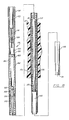
- Plunger 146 comprises a first cylindrical portion 148 (in some embodiments may have a portion thereof, intermediate its ends, relieved to form two spaced cylindrical surfaces which together correspond to portion 148) having an electrical contact 36 at one end. Extending from the opposite end is a second cylindrical portion 152 of a smaller diameter and in alignment with a common longitudinal axis 154. Extending from the other end of the portion 152 is a wand portion 156 of yet a smaller diameter and terminating in a bulbous contact portion 158 of a diameter substantially identical to that of the second cylindrical portion 152.
- the plunger is of heat treated beryllium copper 33-25 or M25, being one-half hard per CDA 173 and plated with 0.00127 millimetres of gold over 0.00254 millimetres of nickel.
- the wand portion 156 in the tested embodiment is 0.234 millimetres in diameter and is offset from the common longitudinal axis 154 a distance of 0.254 millimetres in a length of 4.57 millimetres. As thus sized and constructed, it can be realized that the wand portion 156 acts as a flexible finger with the contact portion 158 at the end thereof.
- plunger tube 160 has an internal diameter sized to be a loose slide fit for the contact portion 158 of plunger 146.
- the plunger tube in the tested embodiment is CDA #725 clad on both sides with gold alloy.
- the socket tube of the present invention s generally indicated as 162.
- the socket tube 162 in the tested embodiment is of beryllium copper alloy clad with a silver alloy on the internal surfaces.
- end 164 of tube 162 is sized to receive end 140 of plug housing 130.
- end 140 is inserted into end 164 and the tube crimped together, a secure point of mechanical and electrical contact to socket tube 162 is provided.
- Socket tube 162 is indented at 166.
- plunger tube 160 The outer diameter of plunger tube 160 is sized such that it can be slid into socket tube 162 and be held in place adjacent the ends 140, 164 by the interference fit pressure of the indentation 166. Prior to such insertion, however, bulbous end 158 is inserted into the plunger tube 160 and the end at 168 crimped about the wand 156 to a size that allows the wand 156 to easily slide therethrough, but being of an opening size insufficient to allow the bulbous end portion 158 to pass back therethrough. Accordingly, contact portion 158 is trapped within the plunger tube 160.
- compression spring 170 is slid over the wand 156 and second cylindrical portion 152 into abutment with the shoulder 172 where the second cylindrical portion 152 joins the first cylindrical portion 148. Then, as the plunger tube is positioned and crimped, the spring 170 is trapped between the shoulder 172 and the end 168 of the plunger tube 160. Thereafter, the plunger tube 160 is positioned within the socket tube 162 as shown in Fig. 18, which holds the entire probe assembly, generally indicated as 174, in assembled condition.
- the probe assembly 174 can be disposed within a bore 32 on a fixture 20 and is held in place by the snug gripping action of one or more raised areas 176 on the outer periphery of the tube 162. These raised areas 176 are preferably disposed in a portion of the socket tube 162 remote from the inner most projection, in use, of the first cylindrical portion 148 into the socket tube.
- the wand 156 As the plunger tube 160 is slid into the socket tube 162 followed by the cylindrical portion 148 of the plunger 146, the wand 156, of necessity, is straightened out from its offset position, thus creating a biasing force by the contact portion 158 against the interior precious metal clad surface of the plunger tube 160.
- the contact portion 158 is held firmly against the inside of the plunger tube 160 throughout its entire length of travel, whereby continuous electrical contact is assured.
- the plunger 146 for example, is of unitary construction.
- the electrical connector is easily removed, while, at the same time, being of small size and affording a firm electrical grip.
- center-to-center dimensions of as little as 1.27 millimetres have been easily obtained with reliable results and ease of use in a probe capable of a longer stroke than prior art probes coupled with higher spring generated contact pressures to ensure reliable electrical contact with PCB's being tested.
Landscapes
- Physics & Mathematics (AREA)
- General Physics & Mathematics (AREA)
- Measuring Leads Or Probes (AREA)
- Adornments (AREA)
- Insulated Conductors (AREA)
Claims (3)
Priority Applications (1)
| Application Number | Priority Date | Filing Date | Title |
|---|---|---|---|
| AT86301121T ATE55652T1 (de) | 1985-03-25 | 1986-02-18 | Elektrische pruefspitze mit anschlussstecker. |
Applications Claiming Priority (2)
| Application Number | Priority Date | Filing Date | Title |
|---|---|---|---|
| US715539 | 1985-03-25 | ||
| US06/715,539 US4659987A (en) | 1985-03-25 | 1985-03-25 | Electrical circuit test probe and connector |
Publications (2)
| Publication Number | Publication Date |
|---|---|
| EP0197637A1 EP0197637A1 (de) | 1986-10-15 |
| EP0197637B1 true EP0197637B1 (de) | 1990-08-16 |
Family
ID=24874461
Family Applications (1)
| Application Number | Title | Priority Date | Filing Date |
|---|---|---|---|
| EP86301121A Expired - Lifetime EP0197637B1 (de) | 1985-03-25 | 1986-02-18 | Elektrische Prüfspitze mit Anschlussstecker |
Country Status (7)
| Country | Link |
|---|---|
| US (1) | US4659987A (de) |
| EP (1) | EP0197637B1 (de) |
| JP (1) | JPH0658379B2 (de) |
| AT (1) | ATE55652T1 (de) |
| CA (1) | CA1249339A (de) |
| DE (1) | DE3673440D1 (de) |
| IE (1) | IE57259B1 (de) |
Families Citing this family (30)
| Publication number | Priority date | Publication date | Assignee | Title |
|---|---|---|---|---|
| US4783624A (en) * | 1986-04-14 | 1988-11-08 | Interconnect Devices, Inc. | Contact probe devices and method |
| US4801876A (en) * | 1986-04-18 | 1989-01-31 | Sagami Tsushin Kogyo Kabushiki Kaisha | Printed wiring board tester |
| JPH0532775Y2 (de) * | 1987-04-17 | 1993-08-20 | ||
| USD311346S (en) | 1987-09-25 | 1990-10-16 | Q.A. Technology Company | Electronic test probe |
| US4885533B1 (en) * | 1988-09-09 | 1998-11-03 | Qa Technology Co Inc | Electrical circuit test probe having an elongate cylindrical retaining and sliding bearing region |
| US5004977A (en) * | 1988-10-24 | 1991-04-02 | Nhk Spring Co., Ltd. | Contact probe |
| US5291129A (en) * | 1988-10-24 | 1994-03-01 | Nhk Spring Co., Ltd. | Contact probe |
| JPH0259471U (de) * | 1988-10-24 | 1990-05-01 | ||
| US4904935A (en) * | 1988-11-14 | 1990-02-27 | Eaton Corporation | Electrical circuit board text fixture having movable platens |
| US4891586A (en) * | 1989-02-13 | 1990-01-02 | Tektronix, Inc. | IC grabber probe |
| US5174763A (en) * | 1990-06-11 | 1992-12-29 | Itt Corporation | Contact assembly |
| EP0462706A1 (de) * | 1990-06-11 | 1991-12-27 | ITT INDUSTRIES, INC. (a Delaware corporation) | Kontaktanordnung |
| US5196789A (en) * | 1991-01-28 | 1993-03-23 | Golden Joseph R | Coaxial spring contact probe |
| US5233290A (en) * | 1991-11-05 | 1993-08-03 | Everett Charles Technologies, Inc. | Switch probe |
| US5484306A (en) * | 1994-10-20 | 1996-01-16 | Interconnect Devices Inc. | Quick-connect terminal and receptacle |
| US6104205A (en) * | 1998-02-26 | 2000-08-15 | Interconnect Devices, Inc. | Probe with tab retainer |
| US6570399B2 (en) * | 2000-05-18 | 2003-05-27 | Qa Technology Company, Inc. | Test probe and separable mating connector assembly |
| US6331836B1 (en) * | 2000-08-24 | 2001-12-18 | Fast Location.Net, Llc | Method and apparatus for rapidly estimating the doppler-error and other receiver frequency errors of global positioning system satellite signals weakened by obstructions in the signal path |
| US6876530B2 (en) * | 2001-01-12 | 2005-04-05 | Qa Technology Company, Inc. | Test probe and connector |
| EP1444528B1 (de) * | 2001-09-24 | 2008-06-25 | Rika Denshi America, Inc. | Elektrische testsonden und verfahren zu ihrer herstellung |
| WO2003076957A1 (en) * | 2002-03-05 | 2003-09-18 | Rika Denshi America, Inc. | Apparatus for interfacing electronic packages and test equipment |
| JP3981042B2 (ja) * | 2003-06-09 | 2007-09-26 | アルプス電気株式会社 | コンタクトプローブ及びプローブソケット及び電気特性測定装置並びにコンタクトプローブの押し当て方法 |
| CN2682641Y (zh) * | 2003-11-20 | 2005-03-02 | 上海莫仕连接器有限公司 | 压接式导电端子 |
| US7298153B2 (en) * | 2005-05-25 | 2007-11-20 | Interconnect Devices, Inc. | Eccentric offset Kelvin probe |
| US7154286B1 (en) * | 2005-06-30 | 2006-12-26 | Interconnect Devices, Inc. | Dual tapered spring probe |
| KR101149758B1 (ko) | 2010-06-30 | 2012-07-11 | 리노공업주식회사 | 프로브 |
| US8262283B2 (en) * | 2010-07-16 | 2012-09-11 | Petroleum Analyzer Company, Lp | Apparatus and method for determining the thermal stability of fluids |
| US20120182034A1 (en) * | 2011-01-17 | 2012-07-19 | 3M Innovative Properties Company | Contact assembly |
| JP5928203B2 (ja) * | 2012-07-10 | 2016-06-01 | 三菱電機株式会社 | 検査装置 |
| KR102172401B1 (ko) * | 2019-12-30 | 2020-10-30 | 조중돈 | 고성능 외통형 스프링핀 |
Citations (1)
| Publication number | Priority date | Publication date | Assignee | Title |
|---|---|---|---|---|
| US4168873A (en) * | 1978-04-03 | 1979-09-25 | Luna L Jack | Wire connections to board terminals |
Family Cites Families (28)
| Publication number | Priority date | Publication date | Assignee | Title |
|---|---|---|---|---|
| US720908A (en) * | 1902-04-02 | 1903-02-17 | Eynon Evans Mfg Company | Condenser. |
| US2896981A (en) * | 1953-08-05 | 1959-07-28 | Pylon Company Inc | Rod joint |
| US2934738A (en) * | 1956-06-07 | 1960-04-26 | Cambridge Thermionic Corp | Electric meter probe |
| US2885648A (en) * | 1956-12-06 | 1959-05-05 | Herbert H King | Test probe with retractible shield |
| US3109689A (en) * | 1959-06-17 | 1963-11-05 | Pylon Company Inc | Terminal |
| US3153561A (en) * | 1960-06-09 | 1964-10-20 | Pyion Company Inc | Resilient electrical connector |
| US3278890A (en) * | 1964-04-13 | 1966-10-11 | Pylon Company Inc | Female socket connector |
| US3416125A (en) * | 1966-10-20 | 1968-12-10 | Ostby & Barton Co | Co-axial connector |
| US3435168A (en) * | 1968-03-28 | 1969-03-25 | Pylon Co Inc | Electrical contact |
| US3562643A (en) * | 1969-01-21 | 1971-02-09 | Ostby & Barton Co | Spring loaded test probe assembly |
| US3675189A (en) * | 1970-12-22 | 1972-07-04 | Ostby & Barton Co | Electrical connector |
| US3753103A (en) * | 1971-11-17 | 1973-08-14 | Crystal Protronics Ass | Electrical circuit test probe having spring biased probe assembly |
| CH589947A5 (en) * | 1974-02-13 | 1977-07-29 | Ingun Ag | Test pin for printed circuit boards - with spring loaded shank in barrel and test end with conical hollow for boards test point |
| US4050762A (en) * | 1976-11-10 | 1977-09-27 | Everett/Charles, Inc. | Telescoping spring probe having separate wiper contact member |
| US4108528A (en) * | 1976-12-06 | 1978-08-22 | Everett/Charles, Inc. | Probe actuator assembly |
| US4114093A (en) * | 1976-12-17 | 1978-09-12 | Everett/Charles, Inc. | Network testing method and apparatus |
| US4138186A (en) * | 1977-07-22 | 1979-02-06 | Everett/Charles, Inc. | Test apparatus |
| US4176900A (en) * | 1977-12-23 | 1979-12-04 | Everett/Charles, Inc. | Low insertion force connector |
| US4377318A (en) * | 1978-02-06 | 1983-03-22 | Everett/Charles, Inc. | Low insertion force electrical interface assembly and actuable interface assembly therefor |
| US4321532A (en) * | 1978-03-16 | 1982-03-23 | Luna L Jack | Repairable spring probe assembly |
| US4209745A (en) * | 1978-06-12 | 1980-06-24 | Everett/Charles, Inc. | Interchangeable test head for loaded test member |
| US4200351A (en) * | 1978-06-12 | 1980-04-29 | Everett/Charles, Inc. | Straight through electrical spring probe |
| US4288745A (en) * | 1980-07-22 | 1981-09-08 | Ostby & Barton Company | Printed circuit board testing means |
| US4427250A (en) * | 1981-01-19 | 1984-01-24 | Everett/Charles Test Equipment, Inc. | Printed circuit board test fixture with compliant platen |
| DE3103077A1 (de) * | 1981-01-30 | 1982-08-26 | Feinmetall Gmbh, 7033 Herrenberg | Federnder kontaktbaustein |
| US4397519A (en) * | 1981-05-12 | 1983-08-09 | Pylon Company, Inc. | Electrical contact construction |
| US4461993A (en) * | 1981-09-21 | 1984-07-24 | Everett/Charles, Inc. | Low resistance electrical spring probe |
| US4409191A (en) * | 1982-01-04 | 1983-10-11 | Exxon Research & Engineering Co. | Integrated cyclic scrubbing and condensate stripping process for the removal of gaseous impurities from gaseous mixtures |
-
1985
- 1985-03-25 US US06/715,539 patent/US4659987A/en not_active Expired - Lifetime
-
1986
- 1986-02-10 IE IE368/86A patent/IE57259B1/en not_active IP Right Cessation
- 1986-02-18 AT AT86301121T patent/ATE55652T1/de not_active IP Right Cessation
- 1986-02-18 EP EP86301121A patent/EP0197637B1/de not_active Expired - Lifetime
- 1986-02-18 DE DE8686301121T patent/DE3673440D1/de not_active Expired - Lifetime
- 1986-03-11 CA CA000503796A patent/CA1249339A/en not_active Expired
- 1986-03-25 JP JP61065044A patent/JPH0658379B2/ja not_active Expired - Lifetime
Patent Citations (1)
| Publication number | Priority date | Publication date | Assignee | Title |
|---|---|---|---|---|
| US4168873A (en) * | 1978-04-03 | 1979-09-25 | Luna L Jack | Wire connections to board terminals |
Also Published As
| Publication number | Publication date |
|---|---|
| US4659987A (en) | 1987-04-21 |
| CA1249339A (en) | 1989-01-24 |
| JPS61223655A (ja) | 1986-10-04 |
| IE57259B1 (en) | 1992-06-17 |
| ATE55652T1 (de) | 1990-09-15 |
| DE3673440D1 (de) | 1990-09-20 |
| JPH0658379B2 (ja) | 1994-08-03 |
| EP0197637A1 (de) | 1986-10-15 |
Similar Documents
| Publication | Publication Date | Title |
|---|---|---|
| EP0197637B1 (de) | Elektrische Prüfspitze mit Anschlussstecker | |
| EP0197636B1 (de) | Elektrische Verbindung für eine elektrische Testspitze | |
| US4526429A (en) | Compliant pin for solderless termination to a printed wiring board | |
| KR102631011B1 (ko) | 인라인 압축 rf 커넥터 | |
| KR100255470B1 (ko) | 고속 케이블의 차폐부 접속 시스템 | |
| US5960540A (en) | Insulated wire with integral terminals | |
| US11005204B2 (en) | High speed electrical connector assembly | |
| US5785555A (en) | System for terminating the shield of a high speed cable | |
| GB1507237A (en) | Electrical contact assembly | |
| US5064389A (en) | Electrical slave connector | |
| GB2124836A (en) | Electrical connectors | |
| US2983895A (en) | Coaxial jack plug | |
| EP0245917B1 (de) | Sofortige Beendigungsvorrichtung und Methode für einen elektrischen Steckverbinder | |
| US5002507A (en) | Circuit board contact element and compliant section thereof | |
| US5484306A (en) | Quick-connect terminal and receptacle | |
| GB2121620A (en) | Connectors pins for printed circuit boards | |
| EP0145315A2 (de) | Verbindungsvorrichtung für in kurzen Abständen angeordnete Leiter und dafür bestimmter elektrischer Kontaktanschluss | |
| GB2187898A (en) | Connecting shield of coaxial cable to p.c.b. | |
| US4036549A (en) | Wire connector | |
| JP4607417B2 (ja) | 両面接点コネクタ | |
| US4266843A (en) | Insulation displacing electrical contact and method of making same | |
| JPH0757792A (ja) | 圧着接続型コネクタ | |
| US5006668A (en) | Connecting mechanism of central conductors of a coaxial cable and a probe | |
| JP3388614B2 (ja) | 電子機器のプラグ用ピンを製造する方法 | |
| JPH1126103A (ja) | コネクタ |
Legal Events
| Date | Code | Title | Description |
|---|---|---|---|
| PUAI | Public reference made under article 153(3) epc to a published international application that has entered the european phase |
Free format text: ORIGINAL CODE: 0009012 |
|
| AK | Designated contracting states |
Kind code of ref document: A1 Designated state(s): AT BE CH DE FR GB IT LI NL SE |
|
| 17P | Request for examination filed |
Effective date: 19870406 |
|
| 17Q | First examination report despatched |
Effective date: 19890503 |
|
| GRAA | (expected) grant |
Free format text: ORIGINAL CODE: 0009210 |
|
| AK | Designated contracting states |
Kind code of ref document: B1 Designated state(s): AT BE CH DE FR GB IT LI NL SE |
|
| PG25 | Lapsed in a contracting state [announced via postgrant information from national office to epo] |
Ref country code: IT Free format text: LAPSE BECAUSE OF FAILURE TO SUBMIT A TRANSLATION OF THE DESCRIPTION OR TO PAY THE FEE WITHIN THE PRE;WARNING: LAPSES OF ITALIAN PATENTS WITH EFFECTIVE DATE BEFORE 2007 MAY HAVE OCCURRED AT ANY TIME BEFORE 2007. THE CORRECT EFFECTIVE DATE MAY BE DIFFERENT FROM THE ONE RECORDED.SCRIBED TIME-LIMIT Effective date: 19900816 Ref country code: CH Effective date: 19900816 Ref country code: AT Effective date: 19900816 Ref country code: BE Effective date: 19900816 Ref country code: LI Effective date: 19900816 Ref country code: NL Effective date: 19900816 Ref country code: SE Free format text: THE PATENT HAS BEEN ANNULLED BY A DECISION OF A NATIONAL AUTHORITY Effective date: 19900816 |
|
| REF | Corresponds to: |
Ref document number: 55652 Country of ref document: AT Date of ref document: 19900915 Kind code of ref document: T |
|
| REF | Corresponds to: |
Ref document number: 3673440 Country of ref document: DE Date of ref document: 19900920 |
|
| REG | Reference to a national code |
Ref country code: CH Ref legal event code: PL |
|
| ET | Fr: translation filed | ||
| NLV1 | Nl: lapsed or annulled due to failure to fulfill the requirements of art. 29p and 29m of the patents act | ||
| PLBE | No opposition filed within time limit |
Free format text: ORIGINAL CODE: 0009261 |
|
| STAA | Information on the status of an ep patent application or granted ep patent |
Free format text: STATUS: NO OPPOSITION FILED WITHIN TIME LIMIT |
|
| 26N | No opposition filed | ||
| REG | Reference to a national code |
Ref country code: GB Ref legal event code: IF02 |
|
| PGFP | Annual fee paid to national office [announced via postgrant information from national office to epo] |
Ref country code: FR Payment date: 20020212 Year of fee payment: 17 |
|
| PGFP | Annual fee paid to national office [announced via postgrant information from national office to epo] |
Ref country code: GB Payment date: 20020220 Year of fee payment: 17 |
|
| PGFP | Annual fee paid to national office [announced via postgrant information from national office to epo] |
Ref country code: DE Payment date: 20020306 Year of fee payment: 17 |
|
| PG25 | Lapsed in a contracting state [announced via postgrant information from national office to epo] |
Ref country code: GB Free format text: LAPSE BECAUSE OF NON-PAYMENT OF DUE FEES Effective date: 20030218 |
|
| PG25 | Lapsed in a contracting state [announced via postgrant information from national office to epo] |
Ref country code: DE Free format text: LAPSE BECAUSE OF NON-PAYMENT OF DUE FEES Effective date: 20030902 |
|
| GBPC | Gb: european patent ceased through non-payment of renewal fee | ||
| PG25 | Lapsed in a contracting state [announced via postgrant information from national office to epo] |
Ref country code: FR Free format text: LAPSE BECAUSE OF NON-PAYMENT OF DUE FEES Effective date: 20031031 |
|
| REG | Reference to a national code |
Ref country code: FR Ref legal event code: ST |