EP0197442B1 - Open-end spinning machine - Google Patents
Open-end spinning machine Download PDFInfo
- Publication number
- EP0197442B1 EP0197442B1 EP86104202A EP86104202A EP0197442B1 EP 0197442 B1 EP0197442 B1 EP 0197442B1 EP 86104202 A EP86104202 A EP 86104202A EP 86104202 A EP86104202 A EP 86104202A EP 0197442 B1 EP0197442 B1 EP 0197442B1
- Authority
- EP
- European Patent Office
- Prior art keywords
- housing
- spinning
- drive
- machine
- opening
- Prior art date
- Legal status (The legal status is an assumption and is not a legal conclusion. Google has not performed a legal analysis and makes no representation as to the accuracy of the status listed.)
- Expired
Links
Images


Classifications
-
- D—TEXTILES; PAPER
- D01—NATURAL OR MAN-MADE THREADS OR FIBRES; SPINNING
- D01H—SPINNING OR TWISTING
- D01H4/00—Open-end spinning machines or arrangements for imparting twist to independently moving fibres separated from slivers; Piecing arrangements therefor; Covering endless core threads with fibres by open-end spinning techniques
- D01H4/04—Open-end spinning machines or arrangements for imparting twist to independently moving fibres separated from slivers; Piecing arrangements therefor; Covering endless core threads with fibres by open-end spinning techniques imparting twist by contact of fibres with a running surface
- D01H4/08—Rotor spinning, i.e. the running surface being provided by a rotor
- D01H4/12—Rotor bearings; Arrangements for driving or stopping
Definitions
- the present invention relates to an open-end rotor spinning machine with a large number of spinning positions located next to one another, each with a spinning rotor, which is arranged in a housing located in a machine-side receptacle and has a drive axis extending transversely to the machine longitudinal direction, by means of which it drives from a drive belt extending in the machine longitudinal direction is driven, wherein the drive axle is mounted in the Zwikkel a support disc bearing.
- a device of this type is known from DE-OS-2515783.
- the spinning rotor rotates at high speeds, so that its bearing is subject to relatively high wear and must therefore be replaced from time to time. This wear occurs more often when there is an imbalance in the spinning rotor.
- the housing accommodating the spinning rotor is removed in order to make the support disk bearing accessible and then also to be able to remove it.
- the support disc bearing When removing and installing the support disc bearing, there is a risk that the support discs will still turn or come to rest against the drive belt and be driven positively. This harbors a risk of injury for the operator, so that the entire machine must always be shut down for safety reasons for the individual removal and installation of a housing.
- the present invention is therefore based on the object of avoiding these disadvantages in a generic open-end spinning machine and of creating a simple device in which the rotor bearing can be exchanged safely while the machine is running.
- the support disc bearing is supported by the housing receiving the spinning rotor, which is mounted on a pivot axis and can be pivoted away from the drive belt at least to such an extent that the housing can be removed from the machine-side receptacle.
- the support disk bearing is lowered so far under the drive belt or raised above the drive belt that the support disks come free from the drive belt and can be removed from the receptacle under the drive belt or over the drive belt. This can be done by a rectilinear or curved movement of the housing with the support disc bearing attached to it or by continuing the initially initiated pivoting movement, which can be released from the receptacle by releasing a lock or screw connection, etc.
- the housing receiving the drive axles with the drive whorls or drive wheels, which accommodates both the opening and the spinning elements is a whole around the pivot axis from it can be swung out on the machine side. This can also be carried out according to the invention in such a way that the second housing is connected to the rotor housing and can be pivoted together with the latter.
- the housing accommodating the spinning rotor and the parts attached to it out of the machine-side receptacle, for example in order to make the support disk bearing accessible for maintenance purposes etc. without removing the housing from the machine
- the machine parts which are stationary with respect to the pivotable housing and the parts attached to it and which are located in the pivoting range of the pivotable parts, have a minimum distance from the pivot axis which is greater than the maximum distance of the parts to be pivoted past these machine parts.
- the maximum distance of a drive axis of the dissolving element from the swivel axis is at least as large as the minimum distance of the drive means of the delivery element from the swivel axis and that Maximum distance of this drive axis from one between the pivot axis and the drive means imaginary vertical plane is smaller than the minimum distance of these drive means from this plane.
- the housing can be pivoted for the purpose of inspection, maintenance or replacement without any risk to the operator.
- the drive means of at least one of the rotating elements are arranged in a channel-like covering which extends over a plurality of spinning stations located next to one another and which carries the pivot axes of the housings of these spinning stations and one longitudinal side of which is covered by these housings.
- This channel enables a compact and low-noise design of the device according to the invention.
- the channel-like covering preferably ends on its side facing away from the pivot axis at a minimum distance that is greater than the maximum distance of the drive axis and / or the support disk bearing from the pivot axis.
- the term “bearing” also includes any lubrication devices for such a bearing.
- the subject of the invention can also be used in connection with a dirt separating device.
- the invention provides that the housing, which is mounted with its upper end receiving the spinning element on the pivot axis, has on its underside a dirt separating opening leading away from the opening element with guide walls extending parallel to the pivot axis, the maximum distance and the maximum distance of the drive axis of the delivery or opening elements from the pivot axis are at least as large, and that below the housing a dirt removal belt in an open top Guide channel is guided, the side walls extend in the direction of the guide walls and the minimum distance from the pivot axis is greater than the maximum distance of the side walls from the pivot axis.
- the side walls of the guide channel do not hinder pivoting movements of the housing in this way, but nevertheless reach up to the immediate vicinity of the guide walls of the dirt separation opening. As a result, the separated dirt arrives safely on the dirt removal belt without the risk
- the guide channel is fastened to the channel-like envelopes carrying the housings of a plurality of spinning stations located next to one another.
- the drive axles of the delivery element and the disengagement element designed as an opening roller have such an inclination with respect to the drive axis of the spinning rotor and the opening roller is arranged in this way relative to the spinning rotor that the fiber feed channel leading from the opening roller to the spinning rotor is arranged and formed symmetrically to the central radial plane through the opening roller.
- a housing accommodating a spinning rotor with a pivotable cover and to provide a stationary brake linkage which can be brought into its braking position by pivoting the cover.
- the brake linkage preferably has one regardless of the position of the cover actuatable control arm. In this way, a spinning station for cleaning the spinning rotor and / or for piecing manually or automatically, e.g. B. be controlled from a piecing car with the cover closed.
- a lock is provided to secure the housing in its operating position and is only accessible after the cover has been swiveled away.
- a locking device securing the housing in its maintenance position is advantageously provided in a further embodiment of the subject matter of the invention.
- a valve that can be controlled as a function of the pivoting position of the housing can also be provided in the vacuum line to the housing. In this way it is inevitably ensured that no loss of vacuum can occur at this spinning point when the housing is pivoted or removed.
- the present invention enables the driven elements of each spinning station to be checked in a simple and safe manner without the entire spinning machine having to be shut down to ensure the safety of the operator.
- This safety for the operator is also given when installing or removing a housing. With this simplicity the construction and this safety for the operator is accompanied by a higher production during this inspection and maintenance phase, since the neighboring spinning stations can continue to work normally without affecting the spinning station to be checked or serviced.
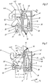
- each spinning station has an individual housing 1 which is pivotally mounted on a pivot axis 10 at its upper end.
- the pivot axis 10 is mounted in a holder 12 carried by the machine frame 11 and extends in the machine longitudinal direction.
- the housing 1 accommodates a delivery device 2, an opening device 3 and a spinning rotor 40.
- a delivery device 2 Of the delivery device 2, only one delivery element designed as a delivery roller 20 is shown in FIG. 1, while the opening device 3 shown has an opening element designed as an opening roller 30.
- a fiber feed channel 31 extends from the opening roller 30 into the interior of the spinning rotor 40.
- a thread draw-off tube 41 carried by a cover 5 leads out of the housing from the interior of the spinning rotor 40.
- the delivery roller 20 is driven by a drive shaft 21 which extends in the longitudinal direction of the machine via a plurality of spinning stations located next to one another and which carries a worm wheel 22 with each spinning station, with which a worm wheel 23 is in engagement.
- This worm wheel 23 is located on the end of a drive shaft 24, on the other end of which the delivery roller 20 is mounted.
- the opening roller 30 is located on the end of a drive shaft 32, the other end of which rests against a drive belt 33 in its operating position.
- the spinning rotor 40 is also carried by a drive axle 42, the free end of which rests against a drive belt 43 in its operating position.
- the spinning rotor 40 is mounted in the gusset of a support disk bearing 44 which, according to the exemplary embodiment shown in FIG. 1, has two pairs of support disks 440 and 441.
- the support disk bearing 44 is attached to the rear of the housing 1 and can therefore be pivoted together with the latter.
- the spinning machine operates in a conventional manner.
- a sliver (not shown) is fed to the opening roller 30 with the aid of the delivery device 2, broken up into individual fibers and fed in this form through the fiber feed channel 31 to the collecting groove of the spinning rotor 40 and deposited there in the form of a fiber ring.
- a thread produced in the spinning rotor 40 is withdrawn from the spinning rotor 40 through the thread draw-off tube 41 with the fiber ring being continuously integrated and wound on a spool (not shown).
- the drive axles 24, 32 and 42 extend transversely to the longitudinal direction of the machine and lie against their drive means (worm wheel 22, drive belt 33 and drive belt 43) at different distances from the pivot axis 10.
- the housing 1 is fixed in its spinning position in a manner not shown, for example with the aid of screws. If the support disc bearing is now to be made accessible for maintenance, replacement, etc., the fixing of the housing 1 is released and this housing 1 is pivoted in the direction of the arrow P.
- the drive shaft 42 is released from the drive belt 43.
- the drive shaft 32 is removed from the drive belt 33 and the worm wheel 23 from the worm wheel 22 ,
- the housing 1 is removed in a manner not shown in the direction of the arrow P 2 from the pivot axis 10 (pivoting a bearing bracket, recess 100 according to FIG. 5 in the pivot axis 10, etc.).
- the support disk bearing 44 is pulled under the drive belt 43.
- the support disc bearing 44 can be supplied with new oil or serviced in some other way. Maintenance of the delivery roller 20 and the opening roller 30 and their bearings is also possible. The neighboring spinning positions are in no way affected by this removal and a later reinstallation of the housing 1 and continue to run undisturbed.
- the cover 5 of the housing 1 is closed during installation and removal. The operator thus comes into contact with all the elements mounted on and in it and with none of the drive means during the installation and removal of the housing 1, and is therefore at no time endangered by these elements or by the elements driven by them.
- Fig. 1 shows an embodiment of the device described, in which the supporting disk La ger 44 can be made accessible only by swiveling out of the machine, with the housing 1 also being able to be removed from the machine if necessary.
- the maximum distance A of the drive axis 42 of the spinning rotor 40 and its support disk bearing 44 closest to the pivot axis 10 is smaller than the minimum distance of the drive means not assigned to the spinning rotor 40 from the pivot axis 10, namely as the minimum distance B of the drive belt 33 the minimum distance C of the drive shaft 21 from this pivot axis 10.
- the maximum distance D of the drive axis 32 of the opening roller 30 from the pivot axis 10 is greater than the minimum distance C of the worm wheel 22 on the drive shaft 21 thereof.
- the drive axles 32 and 24 are substantially equidistant from the pivot axis 10.
- the maximum distance E of the drive axis 32 from an imaginary vertical plane V between the pivot axis 10 and the drive means (worm wheel 22, drive belts 33 and 43) is smaller than the minimum distance F of the worm wheel 22 from this imaginary plane V.
- the housing 1 with deo-rotatable elements (delivery device 2, opening device 3 and spinning element 4) can be pivoted out of the machine about the pivot axis 10 without the drive means (worm wheel 22 and drive belt 33 and 43) are a hindrance here.
- the support disk bearing 44 is accessible.
- Such an element can e.g. B. be a brake that works with one of the driven elements.
- This can also be a support roller 61 or 63 (FIG. 3) for one of the drive belts 43 and 33.
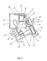
- the arrangement of the rotatable elements (spinning rotor 40, opening device 3 and delivery device 2) in the housing 1 is unchanged from that according to FIG. 1, but the housing is supported at its lower end on the pivot axis 10 .
- the pivot axis 10 is thus located at the end of the housing 1 facing away from the spinning rotor 40.
- the maximum distance G of the worm wheel 23 on the drive axis 24 arranged closest to the pivot axis 10 is smaller than the minimum distances H and K of the pivot axis 10 Drive belts 33 and 43 not assigned to this drive axle 24.
- the maximum distance I of the drive axle 32 from the swivel axle 10 is smaller than the minimum distance K of the drive belt 43 from this swivel axle 10.
- the housing 1 can be swiveled freely to the operating side (arrow P, ), the operating side being arranged to the right of the imaginary vertical plane V in both FIG. 1 and FIG. 2.
- the drive axles 32 and 42 have each applied directly to their drive belts 33 and 43.
- one or both of the drive axles 32 and 42 can carry a swivel with which this drive axle (s) 32 and / or 42 bears against the drive belt 33 and / or 43.
- the specified proportions naturally relate to the whorl if its distance from the pivot axis 10 is greater than the distance from the drive end of the drive axis 32 or 42 thereof.
- Fig. 3 shows an embodiment of the device shown schematically in Fig. 1. Care is taken to ensure that the maximum distance A of the support disk bearing 44 fastened to the housing 1 for the drive axis 42 of the spinning rotor 40 from the pivot axis 10 is smaller than the minimum distance B of the drive means for the opening device 3 and the delivery device 2 (FIG. 11.
- the drive means (drive belt 43) are arranged in a channel-like casing 6, which extends over a large number of spinning stations located next to one another.
- the cover 6 carries between the drive axes 42 of the spinning rotors 40 adjacent spinning stations a holder 60 for support rollers 61 for the drive belt 43.
- the holder 60 and support roller 61 are thus laterally offset outside the pivot range of the with the housing 1 swiveling parts.
- the holders 12 for the pivot axes 10 of the housing 1 of the individual spinning stations extending in the machine longitudinal direction are also attached to the casing 6.
- the channel-like covering 6 is essentially covered by the housing 1 of the adjacent spinning stations.
- the lower side 62 of the channel-like covering 6 faces the drive means (drive belt 33 and drive shaft 21 with worm wheel 22) of the opening device 3 and the delivery device 2 and ends between these drive means.
- the minimum distance L of this side 62 from the pivot axis 10 is greater than the maximum distance A of the drive axis 42 of the support disk bearing 44 for the spinning rotor 40 from this pivot axis 10.
- the channel side 62 is designed as a holder for support rollers 63 for the drive belt 33 of the opening roller 30.
- These support rollers 63 are located between the drive axles 32 of adjacent spinning positions and are therefore generally outside the swivel range of the drive axle 42 and the support disk bearing 44 for the spinning rotor 40. Otherwise, it must be provided that the minimum distance B (FIG. 1) of these support rollers 63 as well that of the drive belt 33 is greater than the maximum distance A of the drive axle 42 and the support disk bearing 44.
- the fiber feed channel 31 is formed symmetrically to the central radial plane R through the opening roller.
- the drive axes 24 and 32 of the delivery device 2 and the opening device 3 are correspondingly inclined with respect to the drive axis 42 of the spinning element 4.
- the delivery device 2 and the opening device 3 are in this way close to the spinning rotor 40, so that the transport path of the individual fibers is short.
- the drive axles 24 and 32 are relatively far away from the drive axle 42 with its bearing 44, which considerably simplifies the inspection and maintenance of these parts.
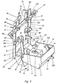
- Fig. 4 shows a further modification of the device described.
- the housing 1, which accommodates both the spinning rotor 40 and the delivery device 2 and the opening device 3, as in the embodiments shown in FIGS. 1 to 3, has on its underside a dirt separating opening 7 leading away from the opening roller 30, which is divided into two Longitudinal machine direction extending guide walls 70 and 71 is shielded.
- the maximum distance M of these guide walls 70 and 71 from the pivot axis 10 is at least as large as the maximum distance M of the drive axis 24 and the worm wheel 23 seated on it from the pivot axis 10.
- the guide channel 72 is delimited by two side walls 73 and 74 which extend in the longitudinal direction of the machine and which extend in the vicinity of the guide walls 70 and 71.
- the minimum distance N of these side walls 73 and 74 from the pivot axis 10 is, however, slightly greater than the maximum distance M of the guide walls 70 and 71 and the worm wheel 23 on the drive axis 24 from this pivot axis 10. In this way it is ensured during production that the on the opening roller 30 discharged dirt is safely guided to the dirt removal belt 75, but on the other hand a pivoting of the housing 1 with the support disk bearing 44 is not impaired for control, maintenance or replacement purposes.
- the front plate 13 of the housing 1 is pivotally mounted between two shield plates 110 of the machine frame with the aid of the pivot axis 10.
- a vacuum line 15 leads from the housing 1 to a collecting line (not shown) which extends in the machine longitudinal direction.
- this vacuum line 15 there is a valve 16 which can be controlled as a function of the pivoting position of the housing 1.
- each holder 12 carries a limit switch 17 which is actuated by the front plate 13 in the operating position of the housing 1 and is released when the housing 1 is pivoted out of its operating position. If the housing 1 is not in its operating position, but is in its maintenance position, or is even removed, the vacuum line 15 is thus blocked by the valve 16; a loss of vacuum at this point is avoided.
- the housing 1 is assigned a locking device 14, from which the arm of a lever 140 extends through an opening 131 in the front plate 13 of the housing 1 to the cover 5.
- the lever 140 is pivotally mounted on the housing 1 and can snap into a retainer (not shown), which is supported by the machine frame, or can be released from it.
- the housing 1 is held in its operating position by the locking device 14, in which all the rotatable elements (delivery roller 20, opening roller 30 and spinning rotor 40) mounted in it are in driving connection to their drive means (worm wheel 22 and to drive belt 33 and 43).
- the lever 140 is only accessible after the cover 5 has been pivoted away. Thus, before the housing 1 is pivoted, the cover 5 must first be opened.
- the cover 5 is mounted on the housing 1 by means of a pivot axis 50 which extends in the machine longitudinal direction.
- the cover 50 carries a stop 51, by means of which it bears against the front plate 13 of the housing 1 when swiveling and thus limits the pivoting movement of the cover 5.
- an angle piece 18 is provided with an opening 180, into which a locking lever 52 engages with its locking lug 520 in the closed position of the cover 5.
- the locking lever 52 is pivotally mounted on the cover 5 and acted upon by a spring 53.
- this latch 520 is released from the opening 180 by exerting pressure on the arm 522 of the latch lever 52 facing away from the latch 520. If the cover 5 is moved back into its closed position, the catch 520 runs with its ramp 521 onto the angle piece 18 and engages in the opening 180 by the action of the spring 53.
- a brake linkage 8 is provided in accordance with the exemplary embodiment shown in FIGS. 5 and 6.
- a bearing 80 is provided on the housing 1, which carries a pivot lever 81 with the aid of a bolt 800, which is articulated to a coupling member 82 at its end facing the cover 5.
- the coupling member 82 is articulated to the cover 5 by means of a bolt 820 in such a way that pivoting the cover 5 causes the pivoting lever 81 to pivot.
- This pivot lever 81 protrudes from the side of the front plate 13 facing the cover 5 through an opening 130 to the rear of the front plate 13 and, as shown in FIG.
- the brake lever 83 extends in the machine longitudinal direction and is pivotably mounted on a stationary axis 84 independently of the housing 1.
- a torsion spring 85 By means of a torsion spring 85, it is held in contact with a stop 832 on the underside of a roller lever 9.
- the stop 832 is designed as a receptacle for a brake insert (not shown) which, when braking, is brought into contact with the drive axis 42 (see FIG. 1) of the spinning rotor 40.
- the ramp-like surface 830 of the brake lever 83 is part of a control arm 831, which is essentially perpendicular to the machine longitudinal direction to the operating side, i. H. to cover 5, extends.
- the roller lever 9 is rotatably mounted on a stationary pivot axis 90 and carries at its one end by means of the axis 84 a roller 91 which can be brought into contact with the drive belt 43 by lifting the brake lever 83 or can be lifted off the latter. Between the spinning stations there are support rollers, not shown, in the usual way below the drive belt 43, which lift the drive belt 43 from the drive axis 42 of the spinning rotor 40 when the drive belt 43 is released by the roller 91. If, on the other hand, the roller 91 is brought back to rest on the drive belt 43, the drive belt 43 also comes into driving contact with the drive axis 42 of the spinning rotor 40.
- the pivot lever 81 is also pivoted via the coupling member 81.
- the roller 810 reaches the surface 830 of the control arm 831 and lifts the stop 832 from the roller lever 9.
- the brake insert arranged in the stop 832 bears against the drive axis 42 of the spinning rotor 40 and thus stops it.
- roller lever 9 is acted upon by a torsion spring 92. This has the result that when the cover 5 is pivoted up - when the roller 810 releases the control arm 831 of the brake lever 83 again - the roller lever 9 brings the roller 91 back into contact with the drive belt 43, while the brake lever 83 engages with its stop 832 the bottom of the roller lever 9 creates. In this way, the drive axle 42 of the spinning rotor 40 is released by the brake insert of the brake lever 83 and driven again by the drive belt 43.
- a brake linkage for the opening roller 30 can also be provided in the same or similar manner.
- driven elements spininning rotor 40, support disks 440 and 441, opening roller 30 and delivery roller 20
- these elements already stand before the pivoting movement of the housing 1 released by the lever 140 silent, so that accidental contact with these elements is without endangering the operator.
- a second locking device 19 is assigned to the housing 1 in the embodiment shown in FIG. 5, which locks the housing 1 in the maintenance position backs up.
- the locking Device 19 has a latch 190 hinged to the shielding plate 110 with a latch-like recess 191 into which the front plate 13 of the housing 1 engages when it is swiveled up.
- the parts mounted in or on the housing 1, in particular the support disks 440 and 441 of the support disk bearing 44 can not only be checked, but also, if necessary, individually removed or installed or also exchanged for other parts.
- the oil level in the support disk bearing 44 can also be checked and, if necessary, corrected by refilling.
- the pivot axis 10 is secured in the holders 12 against rotation.
- the front plate 13 carries two holders 132 with which it and thus the housing 1 is mounted on the pivot axis 10.
- the two holders 132 each have an upward-extending radial slot 133 from their bore receiving the pivot axis 10, which is narrower than the diameter of the pivot axis 10, so that the housing 1 is securely mounted on the pivot axis 10.
- the pivot axis 10 has two diametrically opposite recesses 100 in the region of the two holders 132 such that the pivot axis 10 has a narrow cross-sectional area in this region.
- the recesses 100 are arranged such that the front plate 13 is now more than 90 ° from its operating position shown in FIG. Beyond the maintenance position, must be pivoted until the holder 132 can be removed from the pivot axis 10.
- unlocking of the housing 1 is only possible after the cover 5 has been pivoted away, during which the rotating elements in the housing 1 are stopped. If after the unlocking of the housing 1 by means of the lever 14, the housing 1 is pivoted forward, the drive axles 24, 32 and 42 of these elements are removed from all drive means without the risk of the drive axles and support disks 440 and 441 being in any way the drive means come into contact. There is therefore no risk of injury to the operator by accidentally driven elements in the housing 1.
- the second control arm 831 of the brake lever 83 has the task of being able to control the spinning rotor 40 independently of the pivoting of the cover 5. This can be done manually or with the aid of a maintenance and / or piecing device (not shown) which can be moved along the machine.
- a second drive belt 45 is therefore provided parallel to the drive belt 43, which is driven at a lower speed than the drive belt 43 and can be brought into contact with the drive axis 42 of the spinning rotor 40 by means of a roller 93.
- the roller lever 9 in the embodiment shown is designed as a balance lever which carries the roller 91 on its one arm 900 and the brake lever 83 and the roller 93 on its other arm 901.
- the pivot axis 90 of the roller lever 90 is arranged stationary in the machine with the aid of a bearing 94. So that the pivotability of the housing 1 is not impaired, the roller lever 9 and the brake lever 83 are located on the same side of the drive axis 42 of the spinning rotor 40 as the drive belts 43 and 45.
- the roller 91 can be lifted off the drive belt 43 and the roller 93 for resting on the drive belt 45 by exerting pressure on the control arm 833 for piecing to be brought.
- the drive belt 43 releases the drive axis 42 of the spinning rotor 40, while the drive belt 45 bears against this drive axis 42 and thus drives the spinning rotor 45 at a reduced speed.
- the described embodiments show that by pivoting the housing 1 with the support disk bearing 44 flanged to it, the support disks 440 and 441 can be removed as far up or down from the drive belt 43 or from the drive belts 43 and 45 that the support disks 440 and 441 at one Removing the housing 1 with the drive belts 43 or with the drive belts 43 and 45 no longer come into contact. It does not matter whether the housing 1 is only pulled out to the front after detaching from the pivot axis 10 (arrow P 2 ) or whether the pivoting movement of the housing 1 is continued (arrow P,) until the support disk bearing 44 also without releasing the housing 1 is accessible from the pivot axis 10. Also, the special design of the support disk bearing 44, for example with one or two pairs of support disks, is not of crucial importance for the device described.
- the support disk bearing 44 is attached, as shown in the figures, to a housing 1 which receives both the spinning rotor 40 and the delivery device 2 and the opening device 3. 7 and 8 show, separate housings 45 and 34 can also be provided, of which the first housing 45 accommodates the spinning rotor 40 and the second housing 34 the delivery device 2 and the opening device 3. These housings 45 and 34 can be rigid with one another be connected so that all driving and driven elements of a spinning station are accessible through their joint pivoting.
- the two housings 45 and 34 are mounted independently of one another.
- the (rotor) housing 45 is pivotable a pivot axis 10
- the housing 34 is pivotally mounted on the drive shaft 21 for the delivery roller 20 by means of a bracket 35 (FIG. 7).
- the housing 34 and the cover 5 are held in contact with the rotor housing 45 by elastic means, not shown.
- the rotor housing 45 is again pivoted out of the machine.
- the housing 34 with all the devices mounted in and on it (delivery device 2, opening device 3, cover 5) is first lowered so far that the rotor housing 45 can be pivoted forward.
- all driving and driven elements of a spinning station can be checked without endangering the operator, and depending on the intended swiveling range of the housings 45 and 34 and the element to be checked, there is even no need to remove the housings 45 and / or 34 can.
Description
Die vorliegende Erfindung betrifft eine Offenend-Rotorspinnmaschine mit einer Vielzahl nebeneinander befindlicher Spinnstellen mit je einem Spinnrotor, der in einem in einer maschinenseitigen Aufnahme befindlichen Gehäuse angeordnet ist und eine sich quer zur Maschinenlängsrichtung erstreckende Antriebsachse aufweist, mittels welcher er von einem sich in Maschinenlängsrichtung erstreckenden Antriebsriemen angetrieben wird, wobei die Antriebsachse im Zwikkel eines Stützscheibenlagers gelagert ist. Eine Vorrichtung dieser Art ist durch die DE-OS-2515783 bekannt.The present invention relates to an open-end rotor spinning machine with a large number of spinning positions located next to one another, each with a spinning rotor, which is arranged in a housing located in a machine-side receptacle and has a drive axis extending transversely to the machine longitudinal direction, by means of which it drives from a drive belt extending in the machine longitudinal direction is driven, wherein the drive axle is mounted in the Zwikkel a support disc bearing. A device of this type is known from DE-OS-2515783.
Der Spinnrotor läuft mit hohen Drehzahlen um, so daß dessen Lager einem relativ hohen Verschleiss unterliegt und daher von Zeit zu Zeit ausgewechselt werden muß. Dieser Verschleiß tritt bei einer Umwucht im Spinnrotor verstärkt auf.The spinning rotor rotates at high speeds, so that its bearing is subject to relatively high wear and must therefore be replaced from time to time. This wear occurs more often when there is an imbalance in the spinning rotor.
Zu diesem Zweck wird das den Spinnrotor aufnehmende Gehäuse ausgebaut, um die Stützscheibenlagerung zugänglich zu machen und anschließend ebenfalls ausbauen zu können. Beim Aus- und Einbau der Stützscheibenlagerung besteht die Gefahr, daß sich die Stützscheiben noch drehen oder zur Anlage an den Antriebsriemen gelangen und positiv angetrieben werden. Dies birgt eine Verletzungsgefahr für die Bedienungsperson in sich, so daß aus Sicherheitsgründen zum individuellen Aus- und Einbauen eines Gehäuses stets die gesamte Maschine stillgesetzt werden muß.For this purpose, the housing accommodating the spinning rotor is removed in order to make the support disk bearing accessible and then also to be able to remove it. When removing and installing the support disc bearing, there is a risk that the support discs will still turn or come to rest against the drive belt and be driven positively. This harbors a risk of injury for the operator, so that the entire machine must always be shut down for safety reasons for the individual removal and installation of a housing.
Der vorliegenden Erfindung liegt daher die Aufgabe zugrunde, bei einer gattungsgemäßen Offenend-Spinnmaschine diese Nachteile zu vermeiden und eine einfache Vorrichtung zu schaffen, bei der das Rotorlager bei laufender Maschine gefahrlos ausgewechselt werden kann.The present invention is therefore based on the object of avoiding these disadvantages in a generic open-end spinning machine and of creating a simple device in which the rotor bearing can be exchanged safely while the machine is running.
Diese Aufgabe wird erfindungsgemäß dadurch gelöst, daß das Stützscheibenlager von dem den Spinnrotor aufnehmenden Gehäuse getragen wird, welches auf einer Schwenkachse gelagert ist und mindestens so weit vom Antriebsriemen wegschwenkbar ist, daß das Gehäuse aus der maschinenseitigen Aufnahme herausnehmbar ist. Durch Verschwenken des Gehäuses wird dabei das Stützscheibenlager soweit unter den Antriebsriemen abgesenkt bzw. über den Antriebsriemen angehoben, daß die Stützscheiben vom Antriebsriemen freikommen und unter dem Antriebsriemen hindurch bzw. über den Antriebsriemen hinweg aus der Aufnahme herausgenommen werden können. Dies kann durch eine geradlinige oder kurvenförmige Bewegung des Gehäuses mit dem an ihm angebrachten Stützscheibenlager oder auch durch Fortführung der zunächst eingeleiteten Schwenkbewegung geschehen, wobei eine Loslösung von der Aufnahme durch Lösen einer Verriegelung oder Verschraubung usw. erfolgen kann.This object is achieved in that the support disc bearing is supported by the housing receiving the spinning rotor, which is mounted on a pivot axis and can be pivoted away from the drive belt at least to such an extent that the housing can be removed from the machine-side receptacle. By pivoting the housing, the support disk bearing is lowered so far under the drive belt or raised above the drive belt that the support disks come free from the drive belt and can be removed from the receptacle under the drive belt or over the drive belt. This can be done by a rectilinear or curved movement of the housing with the support disc bearing attached to it or by continuing the initially initiated pivoting movement, which can be released from the receptacle by releasing a lock or screw connection, etc.
Es ist möglich, das Rotorgehäuse unabhängig von einem das Lieferelement und das Auflöseelement aufnehmenden zweiten Gehäuse zu lagern und ein- bzw. auszubauen. Andererseits können sich sowohl am Lieferelement als auch am Auflöseelement Wickel bilden, die zu einer Beschädigung derselben führen. Dasselbe kann bei unsachgemäßer Bedienung der Spinnvorrichtung der Fall sein. Bei derartigen Störungen ist es ebenfalls erforderlich, die beschädigten Teile auszuwechseln. Um die rotierenden Spinnelemente einer Spinnvorrichtung bei laufender Maschine gefahrlos auswechseln zu können, ist gemäß einem weiteren Merkmal der Erfindung das die Antriebsachsen mit den Antriebswirteln oder Antriebsrädern aufnehmende Gehäuse, das sowohl die Auflöse- als auch die Spinnelemente aufnimmt, als Ganzes um die Schwenkachse aus seiner maschinenseitigen Aufnahme herausschwenkbar. Dies kann erfindungsgemäß auch in der Weise durchgeführt werden, daß das zweite Gehäuse mit dem Rotorgehäuse verbunden und mit diesem zusammen verschwenkbar ist.It is possible to store and install or remove the rotor housing independently of a second housing which receives the delivery element and the opening element. On the other hand, windings can form both on the delivery element and on the opening element, which lead to damage thereof. The same can be the case if the spinning device is operated improperly. In the event of such malfunctions, it is also necessary to replace the damaged parts. In order to be able to safely replace the rotating spinning elements of a spinning device while the machine is running, according to a further feature of the invention, the housing receiving the drive axles with the drive whorls or drive wheels, which accommodates both the opening and the spinning elements, is a whole around the pivot axis from it can be swung out on the machine side. This can also be carried out according to the invention in such a way that the second housing is connected to the rotor housing and can be pivoted together with the latter.
Um das den Spinnrotor aufnehmende Gehäuse und die an ihm befestigten Teile bis aus der maschinenseitigen Aufnahme herausschwenken zu können, um beispielsweise ohne Abnahme des Gehäuses von der Maschine die Stützscheibenlagerung für Wartungszwecke usw. zugänglich zu machen, kann in weiterer Ausgestaltung der Erfindung vorgesehen sein, daß die Maschinenteile, die gegenüber dem schwenkbaren Gehäuse und die an ihm angebrachten Teile ortsfest sind und die sich im Schwenkbereich der schwenkbaren Teile befinden, einen Mindestabstand von der Schwenkachse aufweisen, der größer als der Maximalabstand der an diesen Maschinenteilen vorbeizuschwenkenden Teile ist. Auf diese Weise wird sichergestellt, daß das Gehäuse mit allen von ihm getragenen Teilen unbehindert durch Antriebsmittel, Bremsen usw., aus dem Maschinengestell herausgeschwenkt werden kann, so daß die Antriebsachse sowie die Stützscheibenlagerung durch Augenschein kontrolliert werden können. Durch die Schwenkbewegung des Gehäuses wird die Antriebsachse von ihrem Antriebsriemen getrennt und so weit entfernt, daß während des späteren Ausbaus auch unabsichtlich kein vorübergehender erneuter Antrieb der drehbar im Gehäuse gelagerten Elemente möglich ist. Die Kontrolle der am Gehäuse angebrachten Elemente kann somit ohne Gefahr für die Bedienungsperson auch bei laufender Maschine durchgeführt werden. Außerdem können bei laufender Maschine sowohl das komplette, den Spinnrotor aufnehmende Gehäuse als auch Teile hiervon aus- oder eingebaut oder auch ausgetauscht werden, so daß die anderen Spinnstellen ungestört weiterarbeiten können.In order to be able to pivot the housing accommodating the spinning rotor and the parts attached to it out of the machine-side receptacle, for example in order to make the support disk bearing accessible for maintenance purposes etc. without removing the housing from the machine, it can be provided in a further embodiment of the invention that the machine parts, which are stationary with respect to the pivotable housing and the parts attached to it and which are located in the pivoting range of the pivotable parts, have a minimum distance from the pivot axis which is greater than the maximum distance of the parts to be pivoted past these machine parts. In this way it is ensured that the housing with all parts carried by it can be swiveled out of the machine frame unimpeded by drive means, brakes, etc., so that the drive axle and the support disk bearing can be checked by eye. The pivoting movement of the housing separates the drive axle from its drive belt and removes it so far that during the subsequent expansion, it is also inadvertently impossible to temporarily drive the rotatably mounted elements in the housing. The control of the elements attached to the housing can thus be carried out without the operator being at risk even when the machine is running. In addition, while the machine is running, both the complete housing accommodating the spinning rotor and parts thereof can be removed or installed or exchanged, so that the other spinning positions can continue to operate undisturbed.
In weiterer vorteilhafter Ausgestaltung des Erfindungsgegenstandes kann bei annähernd in gleichem Abstand von der Schwenkachse angeordneten Liefer- und Auflöseelementen vorgesehen werden, daß der Maximalabstand einer Antriebsachse des Auflöseelementes von der Schwenkachse mindestens ebenso groß ist wie der Mindestabstand der Antriebsmittel des Lieferelementes von der Schwenkachse und daß der Maximalabstand dieser Antriebsachse von einer zwischen der Schwenkachse und den Antriebsmitteln befindlichen imaginären vertikalen Ebene kleiner ist als der Mindestabstand dieser Antriebsmittel von dieser Ebene. Auch in diesem Fall kann das Gehäuse ohne Gefahr für die Bedienungsperson zwecks Kontrolle, Wartung oder Austausch verschwenkt werden.In a further advantageous embodiment of the subject matter of the invention, with delivery and dissolving elements arranged at approximately the same distance from the swivel axis, the maximum distance of a drive axis of the dissolving element from the swivel axis is at least as large as the minimum distance of the drive means of the delivery element from the swivel axis and that Maximum distance of this drive axis from one between the pivot axis and the drive means imaginary vertical plane is smaller than the minimum distance of these drive means from this plane. In this case, too, the housing can be pivoted for the purpose of inspection, maintenance or replacement without any risk to the operator.
Gemäß einer baulich einfachen Ausführung sind die Antriebsmittel wenigstens eines der rotierenden Elemente in einer sich über eine Vielzahl nebeneinander befindlicher Spinnstellen erstrekkenden kanalartigen Umhüllung angeordnet, welche die Schwenkachsen der Gehäuse dieser Spinnstellen trägt und deren eine Längsseite durch diese Gehäuse abgedeckt ist. Dieser Kanal ermöglicht eine kompakte und geräuscharme Ausbildung der erfindungsgemäßen Vorrichtung.According to a structurally simple embodiment, the drive means of at least one of the rotating elements are arranged in a channel-like covering which extends over a plurality of spinning stations located next to one another and which carries the pivot axes of the housings of these spinning stations and one longitudinal side of which is covered by these housings. This channel enables a compact and low-noise design of the device according to the invention.
Vorzugsweise endet bei einer solchen Ausgestaltung des Erfindungsgegenstandes die kanalartige Umhüllung an ihrer der Schwenkachse abgewandten Seite in einem Mindestabstand, der größer ist als der Maximalabstand der Antriebsachse und/oder des Stützscheibenlagers von der Schwenkachse. Im Sinne der vorliegenden Erfindung schließt der Begriff «Lager» auch eventuelle Schmiereinrichtungen für ein solches Lager ein. Vorteilhafterweise endet dabei die Seite der kanalartigen Umhüllung, welche den Antriebsmitteln für die Auflöse- und für die Lieferelemente zugewandt ist, zwischen diesen Antriebsmitteln und ist dabei als Halterung für die Antriebsmittel der Auflöse- und/oder Lieferelemente ausgebildet.In such an embodiment of the subject matter of the invention, the channel-like covering preferably ends on its side facing away from the pivot axis at a minimum distance that is greater than the maximum distance of the drive axis and / or the support disk bearing from the pivot axis. For the purposes of the present invention, the term “bearing” also includes any lubrication devices for such a bearing. Advantageously, the side of the channel-like covering, which faces the drive means for the opening and for the delivery elements, ends between these drive means and is designed as a holder for the drive means for the opening and / or delivery elements.
Der Erfindungsgegenstand kann auch in Verbindung mit einer Schmutzabscheidevorrichtung Anwendung finden. Um bei einem Verschwenken des Gehäuses keine Verbindungsleitungen zwischen dem Gehäuse und einer Schmutzabtransportvorrichtung lösen und später wieder herstellen zu müssen, ist gemäß einer besonders vorteilhaften Ausführung erfindungsgemäß vorgesehen, daß das Gehäuse, welches mit seinem oberen, das Spinnelement aufnehmenden Ende auf der Schwenkachse gelagert ist, auf seiner Unterseite eine vom Auflöseelement wegführende Schmutzabscheideöffnung mit sich parallel zur Schwenkachse erstreckenden Leitwänden aufweist, deren Maximalabstand und der Maximalabstand der Antriebsachse der Liefer- bzw. Auflöseelemente von der Schwenkachse mindestens ebenso groß sind, und daß unterhalb des Gehäuses ein Schmutzabtransportband in einem nach oben offenen Führungskanal geführt ist, dessen Seitenwände sich in Richtung zu den Leitwänden erstrecken und deren Mindestabstand von der Schwenkachse größer ist als der Maximalabstand der Seitenwände von der Schwenkachse. Die Seitenwände des Führungskanals behindern auf diese Weise Schwenkbewegungen des Gehäuses nicht, reichen aber dennoch bis in unmittelbare Nähe der Leitwände der Schmutzabscheideöffnung heran. Der ausgeschiedene Schmutz gelangt hierdurch sicher auf das Schmutzabtransportband, ohne daß die Gefahr der Verflugung der Spinnmaschine besteht.The subject of the invention can also be used in connection with a dirt separating device. In order not to have to disconnect and later to reconnect connecting lines between the housing and a dirt removal device when the housing is pivoted, according to a particularly advantageous embodiment, the invention provides that the housing, which is mounted with its upper end receiving the spinning element on the pivot axis, has on its underside a dirt separating opening leading away from the opening element with guide walls extending parallel to the pivot axis, the maximum distance and the maximum distance of the drive axis of the delivery or opening elements from the pivot axis are at least as large, and that below the housing a dirt removal belt in an open top Guide channel is guided, the side walls extend in the direction of the guide walls and the minimum distance from the pivot axis is greater than the maximum distance of the side walls from the pivot axis. The side walls of the guide channel do not hinder pivoting movements of the housing in this way, but nevertheless reach up to the immediate vicinity of the guide walls of the dirt separation opening. As a result, the separated dirt arrives safely on the dirt removal belt without the risk of the spinning machine flying away.
In zweckmässiger Ausgestaltung des Erfindungsgegenstandes ist der Führungskanal an der die Gehäuse mehrerer nebeneinander befindlicher Spinnstellen tragenden kanalartigen Umhüllungen befestigt.In an expedient embodiment of the subject matter of the invention, the guide channel is fastened to the channel-like envelopes carrying the housings of a plurality of spinning stations located next to one another.
Eine Kontrolle der Antriebsachsen und ihrer Lagerungen wird umso mehr erleichtert, je mehr diese voneinander entfernt sind. Um dennoch eine kompakte Anordnung der angetriebenen Elemente sowie einen möglichst kurzen, die Fasern schonend führenden Faserspeisekanal zu erzielen, weisen die Antriebsachsen des Lieferelementes und des als Auflösewalze ausgebildeten Auflöseelementes gegenüber der Antriebsachse des Spinnrotors eine solche Neigung auf und ist die Auflösewalze gegenüber dem Spinnrotor derart angeordnet, daß der von der Auflösewalze zum Spinnrotor führende Faserspeisekanal symmetrisch zu der mittleren, durch die Auflösewalze gelegten Radialebene angeordnet und ausgebildet ist.It is easier to check the drive axles and their bearings the more they are apart. In order to achieve a compact arrangement of the driven elements and the shortest possible fiber feed channel that gently guides the fibers, the drive axles of the delivery element and the disengagement element designed as an opening roller have such an inclination with respect to the drive axis of the spinning rotor and the opening roller is arranged in this way relative to the spinning rotor that the fiber feed channel leading from the opening roller to the spinning rotor is arranged and formed symmetrically to the central radial plane through the opening roller.
Es ist üblich, ein einen Spinnrotor aufnehmendes Gehäuse mit einer schwenkbaren Abdeckung zu versehen, und ein durch Verschwenken der Abdeckung in seine Bremsstellung bringbares, ortsfest gelagertes Bremsgestänge vorzusehen. Um zu ermöglichen, daß einerseits durch das Verschwenken der das Gehäuse verschließenden Abdeckung eines oder mehrerer der rotierenden Elemente einer Spinnstelle stillgesetzt werden können, daß dies aber auch bei sich in Schließstellung befindlicher Abdeckung möglich ist, besitzt vorzugsweise das Bremsgestänge einen unabhängig von der Position der Abdeckung betätigbaren Steuerarm. Auf diese Weise kann eine Spinnstelle für ein Reinigen des Spinnrotors und/oder für ein Anspinnen manuell oder automatisch, z. B. von einem Anspinnwagen aus, bei geschlossener Abdeckung gesteuert werden.It is customary to provide a housing accommodating a spinning rotor with a pivotable cover and to provide a stationary brake linkage which can be brought into its braking position by pivoting the cover. In order to enable that, on the one hand, the pivoting of the cover closing the housing of one or more of the rotating elements of a spinning station can be stopped, but that this is also possible when the cover is in the closed position, the brake linkage preferably has one regardless of the position of the cover actuatable control arm. In this way, a spinning station for cleaning the spinning rotor and / or for piecing manually or automatically, e.g. B. be controlled from a piecing car with the cover closed.
Um ein unbeabsichtigtes Verschwenken des Gehäuses auszuschließen, ist eine das Gehäuse in seiner Betriebsstellung sichernde Verriegelung vorgesehen, die erst nach Abschwenken der Abdeckung zugänglich ist.In order to prevent the housing from swiveling unintentionally, a lock is provided to secure the housing in its operating position and is only accessible after the cover has been swiveled away.
Um für Inspektions- und Wartungsarbeiten beide Hände frei zu haben, ist in weiterer Ausgestaltung des Erfindungsgegenstandes vorteilhafterweise eine das Gehäuse in seiner Wartungsstellung sichernde Verriegelungsvorrichtung vorgesehen.In order to have both hands free for inspection and maintenance work, a locking device securing the housing in its maintenance position is advantageously provided in a further embodiment of the subject matter of the invention.
Zweckmäßigerweise kann ferner ein in Abhängigkeit von der Schwenkposition des Gehäuses steuerbares Ventil in der Unterdruckleitung zum Gehäuse vorgesehen sein. Auf diese Weise wird zwangsläufig sichergestellt, daß bei verschwenktem oder abgenommenem Gehäuse an dieser Spinnstelle kein Unterdruckverlust auftreten kann.Expediently, a valve that can be controlled as a function of the pivoting position of the housing can also be provided in the vacuum line to the housing. In this way it is inevitably ensured that no loss of vacuum can occur at this spinning point when the housing is pivoted or removed.
Die vorliegende Erfindung ermöglicht auf einfache und sichere Weise eine Kontrolle der angetriebenen Elemente einer jeden Spinnstelle, ohne daß zur Wahrung der Sicherheit der Bedienungsperson die gesamte Spinnmaschine abgestellt werden muß. Diese Sicherheit für die Bedienungsperson ist auch während eines Ein- oder Ausbaues eines Gehäuses gegeben. Mit dieser Einfachheit der Konstruktion und mit dieser Sicherheit für die Bedienungsperson geht eine höhere Produktion während dieser Kontroll- und Wartungsphase einher, da die benachbarten Spinnstellen ohne Beeinträchtigung der zu kontrollierenden oder zu wartenden Spinnstelle normal weiterarbeiten können.The present invention enables the driven elements of each spinning station to be checked in a simple and safe manner without the entire spinning machine having to be shut down to ensure the safety of the operator. This safety for the operator is also given when installing or removing a housing. With this simplicity the construction and this safety for the operator is accompanied by a higher production during this inspection and maintenance phase, since the neighboring spinning stations can continue to work normally without affecting the spinning station to be checked or serviced.
Die Erfindung wird nachstehend anhand mehrerer Ausführungsbeispiele näher erläutert.The invention is explained in more detail below using several exemplary embodiments.
Es zeigen:
- Fig. 1 im Schema eine erste Ausbildung einer erfindungsgemäß ausgebildeten Spinnstelle im Schnitt;
- Fig. 2 im Schema eine zweite Ausbildung einer erfindungsgemäß ausgebildeten Spinnstelle im Schnitt;
- Fig. 3 im Schnitt ein Ausführungsbeispiel der in Fig. 1 schematisch gezeigten Ausbildung des Erfindungsgegenstandes;
- Fig. 4 im Schnitt eine Abwandlung der in Fig. 3 gezeigten Vorrichtung in Verbindung mit einer Schmutzabscheidevorrichtung;
- Fig. 5 in perspektivischer Ansicht eine weitere Abwandlung einer erfindungsgemäß ausgebildeten Spinnstelle;
- Fig. 6 ein Detail der in Fig. 5 gezeigten Vorrichtung, und
- Fig. 7 und 8 eine abgewandelte Ausführung der erfinderischen Vorrichtung im Schnitt in ihrer Spinn- bzw. in ihrer Wartungsstellung.
- Figure 1 in the scheme a first embodiment of a spinning station designed according to the invention in section.
- 2 shows a second embodiment of a spinning station designed according to the invention in section in the diagram;
- 3 shows in section an embodiment of the embodiment of the subject of the invention shown schematically in FIG. 1;
- 4 shows in section a modification of the device shown in FIG. 3 in connection with a dirt separating device;
- 5 is a perspective view of a further modification of a spinning station designed according to the invention;
- Fig. 6 shows a detail of the device shown in Fig. 5, and
- 7 and 8 a modified embodiment of the inventive device in section in its spinning or in its maintenance position.
Das Prinzip der Erfindung wird zunächst anhand der Fig. 1 erläutert. Wie hieraus ersichtlich, weist jede Spinnstelle ein individuelles Gehäuse 1 auf, welches an seinem oberen Ende auf einer Schwenkachse 10 schwenkbar gelagert ist. Die Schwenkachse 10 ist in einem vom Maschinengestell 11 getragenen Halter 12 gelagert und erstreckt sich in Maschinenlängsrichtung.The principle of the invention is first explained with reference to FIG. 1. As can be seen from this, each spinning station has an
Das Gehäuse 1 nimmt eine Liefervorrichtung 2, eine Auflösevorrichtung 3 sowie einen Spinnrotor 40 auf. Von der Liefervorrichtung 2 ist in Fig. 1 lediglich ein als Lieferwalze 20 ausgebildetes Lieferelement gezeigt, während die gezeigte Auflösevorrichtung 3 ein als Auflösewalze 30 ausgebildetes Auflöseelement aufweist.The
Von der Auflösewalze 30 erstreckt sich ein Faserspeisekanal 31 in das Innere des Spinnrotors 40. Ausserdem führt aus dem Inneren des Spinnrotors 40 ein von einer Abdeckung 5 getragenes Fadenabzugsrohr 41 aus dem Gehäuse heraus.A
Die Lieferwalze 20 wird von einer sich in Maschinenlängsrichtung über eine Vielzahl nebeneinander befindlicher Spinnstellen erstreckenden Antriebswelle 21 angetrieben, die pro Spinnstelle ein Schneckenrad 22 trägt, mit welcher ein Schneckenrad 23 in Eingriff steht. Dieses Schnekkenrad 23 befindet sich auf dem Ende einer Antriebsachse 24, auf deren anderen Ende die Lieferwalze 20 gelagert ist.The
Die Auflösewalze 30 befindet sich auf dem Ende einer Antriebsachse 32, deren anderes Ende in ihrer Betriebslage an einem Antriebsriemen 33 anliegt. Auch der Spinnrotor 40 wird von einer Antriebsachse 42 getragen, deren freies Ende in ihrer Betriebslage an einem Antriebsriemen 43 anliegt.The opening
Der Spinnrotor 40 ist im Zwickel eines Stützscheibenlagers 44 gelagert, das gemäß dem in Fig. 1 gezeigten Ausführungsbeispiel zwei Paar Stützscheiben 440 und 441 aufweist. Das Stützscheibenlager 44 ist an der Rückseite des Gehäuses 1 angebracht und deshalb mit diesem gemeinsam verschwenkbar.The spinning
Die Spinnmaschine, von welcher vorstehend der Aufbau einer Spinnstelle beschrieben wurde, arbeitet in herkömmlicher Weise. Ein nichtgezeigtes Faserband wird mit Hilfe der Liefervorrichtung 2 der Auflösewalze 30 zugeführt, von dieser in Einzelfasern aufgelöst und in dieser Form durch den Faserspeisekanal 31 der Sammelrille des Spinnrotors 40 zugeführt und dort in Form eines Faserringes abgelegt. Ein im Spinnrotor 40 erzeugter Faden wird unter kontinuierlicher Einbindung des Faserringes durch das Fadenabzugsrohr 41 aus dem Spinnrotor 40 abgezogen und auf einer nichtgezeigten Spule aufgewickelt.The spinning machine, of which the structure of a spinning station has been described above, operates in a conventional manner. A sliver (not shown) is fed to the
Wie Fig. 1 zeigt, erstrecken sich die Antri3bsach- sen 24, 32 und 42 quer zur Maschinenlängsrichtung und legen sich in unterschiedlichem Abstand von der Schwenkachse 10 an ihre Antriebsmittel (Schneckenrad 22, Antriebsriemen 33 und Antriebsriemen 43) an.As shown in FIG. 1, the
Das Gehäuse 1 wird in nicht gezeigter Weise, z.B. mit Hilfe von Schrauben, in seiner Spinnstellung fixiert. Soll nun das Stützscheibenlager zwecks Wartung, Austausch usw. zugänglich gemacht werden, so wird die Fixierung des Gehäuses 1 gelöst und dieses Gehäuse 1 in Richtung des Pfeiles P, verschwenkt. Dabei löst sich die Antriebsachse 42 vom Antriebsriemen 43. Gleichzeitig entfernen sich die Antriebsachse 32 vom Antriebsriemen 33 und das Schneckenrad 23 vom Schneckenrad 22. Wenn das Gehäuse 1 soweit verschwenkt ist, daß die Stützscheiben 440 und 441 beim Vorziehen nicht mehr am Antriebsriemen 43 hängenbleiben kann, wird das Gehäuse 1 in nicht gezeigter Weise in Richtung des Pfeiles P2 von der Schwenkachse 10 abgenommen (Verschwenken einer Lagerlasche, Ausnehmung 100 gemäß Fig. 5 in der Schwenkachse 10 usw.). Das Stützscheibenlager 44 wird dabei unter dem Antriebsriemen 43 hindurch gezogen. Nun kann das Stützscheibenlager 44 mit neuem Öl versorgt oder in anderer Weise gewartet werden. Ebenso ist eine Wartung der Lieferwalze 20 und der Auflösewalze 30 und ihrer Lager möglich. Die benachbarten Spinnstellen werden durch diese Herausnahme und ein späteres Wiedereinsetzen des Gehäuses 1 in keiner Weise beeinträchtigt und laufen ungestört weiter. Während des Ein- und Ausbaues ist die Abdeckung 5 des Gehäuses 1 verschlossen. Die Bedienungsperson kommt somit während des Ein- und Ausbaues des Gehäuses 1 mit all den an und in ihm gelagerten Elementen und mit keinem der Antriebsmittel in Kontakt, wird somit in keinem Augenblick durch diese oder durch die durch diese angetriebenen Elemente gefährdet.The
Fig. 1 zeigt eine Ausgestaltung der beschriebenen Vorrichtung, bei welcher das Stützscheibenlager 44 allein durch Herausschwenken aus der Maschine zugänglich gemacht werden kann, wobei gegebenenfalls auch dann noch das Gehäuse 1 von der Maschine abgenommen werden kann.Fig. 1 shows an embodiment of the device described, in which the supporting
Um trotz des unterschiedlichen Abstandes der Antriebsmittel von der Schwenkachse 10 des Gehäuses 1 zu vermeiden, daß beim Verschwenken des Gehäuses die Antriebsachsen 24, 32 und 42 in Kontakt mit irgendeinem dieser Antriebsmittel (Schneckenrad 22, Antriebsriemen 33 und 43) gelangen können, befinden sich das Stützscheibenlager 44 und die Antriebsachsen 24, 32 und 42 sowie die Antriebsmittel bei der gezeigten Ausführung in einer festgelegten Anordnung zueinander. So ist der Maximalabstand A der am nächsten bei der Schwenkachse 10 befindlichen Antriebsachse 42 des Spinnrotors 40 und seines Stützscheibenlagers 44 von der Schwenkachse 10 kleiner als der Mindestabstand der nicht dem Spinnrotor 40 zugeordneten Antriebsmittel von der Schwenkachse 10, nämlich als der Mindestabstand B des Antriebsriemens 33 der Mindestabstand C der Antriebswelle 21 von dieser Schwenkachse 10.In order to prevent the
Beim gezeigten Ausführungsbeispiel ist zwar der Maximalabstand D der Antriebsachse 32 der Auflösewalze 30 von der Schwenkachse 10 größer als der Mindestabstand C des Schneckenrades 22 auf der Antriebswelle 21 hiervon. Statt dessen sind jedoch die Antriebsachsen 32 und 24 im wesentlichen gleich weit von der Schwenkachse 10 entfernt. Ausserdem ist der Maximalabstand E der Antriebsachse 32 von einer imaginären vertikalen Ebene V zwischen der Schwenkachse 10 und den Antriebsmitteln (Schneckenrad 22, Antriebsriemen 33 und 43) kleiner als der Mindestabstand F des Schneckenrades 22 von dieser imaginären Ebene V.In the exemplary embodiment shown, the maximum distance D of the
Durch Einhaltung der erwähnten Abstände wird erreicht, daß das Gehäuse 1 mit deo in ihm gelagerten drehbaren Elementen (Liefervorrichtung 2, Auflösevorrichtung 3 und Spinnelement 4) um die Schwenkachse 10 aus der Maschine herausgeschwenkt werden kann, ohne daß die Antriebsmittel (Schneckenrad 22 sowie Antriebsriemen 33 und 43) hierbei hinderlich sind. Hierdurch wird insbesondere das Stützscheibenlager 44 zugänglich.By observing the above-mentioned distances, it is achieved that the
Diese Maßverhältnisse sind nicht nur in bezug auf die unabhängig vom Gehäuse 1 in der Maschine angeordneten Antriebsmittel einzuhalten, sondern auch gegenüber anderen, vom Gehäuse 1 unabhängigen Elementen, sofern sie sich auf der der Schwenkachse 10 abgewandten Seite der Antriebsachsen 42, 32 und 24 befinden. Auf diese Weise ist sichergestellt, daß die Schwenkbewegung des Gehäuses 1 durch diese Elemente nicht beeinträchtigt wird. Ein solches Element kann z. B. eine Bremse sein, die mit einem der angetriebenen Elemente zusammenarbeitet. Es kann sich hierbei auch um eine Stützrolle 61 bzw. 63 (Fig. 3) für einen der Antriebsriemen 43 und 33 handeln.These dimensions are to be observed not only with regard to the drive means arranged independently of the
Bei einem abgeänderten, in Fig. 2 gezeigten Ausführungsbeispiel ist die Anordnung der drehbaren Elemente (Spinnrotor 40, Auflösevorrichtung 3 und Liefervorrichtung 2) im Gehäuse 1 gegenüber jener gemäß Fig. 1 unverändert, doch ist das Gehäuse an seinem unteren Ende auf der Schwenkachse 10 gelagert. Die Schwenkachse 10 befindet sich somit an dem dem Spinnrotor 40 abgewandten Ende des Gehäuses 1. Bei diesem Ausführungsbeispiel ist der Maximalabstand G des Schneckenrades 23 auf der am nächsten bei der Schwenkachse 10 angeordneten Antriebsachse 24 von der Schwenkachse 10 kleiner als die Mindestabstände H und K der nicht dieser Antriebsachse 24 zugeordneten Antriebsriemen 33 und 43. Außerdem ist auch der Maximalabstand I der Antriebsachse 32 von der Schwenkachse 10 kleiner als der Mindestabstand K des Antriebsriemens 43 von dieser Schwenkachse 10. Auch hier kann das Gehäuse 1 ungehindert zur Bedienungsseite verschwenkt (Pfeil P,) werden, wobei sowohl in der Fig. 1 als auch in der Fig. 2 die Bedienungsseite rechts von der imaginären vertikalen Ebene V angeordnet ist.In a modified embodiment shown in FIG. 2, the arrangement of the rotatable elements (spinning
Bei den in den Fig. 1 und 2 gezeigten Ausführungen haben sich die Antriebsachsen 32 und 42 jeweils direkt an ihre Antriebsriemen 33 und 43 angelegt. Abweichend von den gezeigten Ausführungen kann eine der oder können beide Antriebsachsen 32 und 42 einen Wirbel tragen, mit dem sich diese Antriebsachse(n) 32 und/oder 42 an den Antriebsriemen 33 und/oder 43 anlegt. Die angegebenen Maßverhältnisse beziehen sich dann natürlich auf den Wirtel, wenn dessen Abstand von der Schwenkachse 10 größer als der Abstand des Antriebsendes der Antriebsachse 32 bzw. 42 hiervon ist.In the embodiments shown in FIGS. 1 and 2, the
Weitere Abwandlungen durch Austausch von Merkmalen untereinander oder durch ihren Ersatz durch Äquivalente sowie Kombinationen hiervon sind möglich. So ist es auch denkbar, die Liefervorrichtung 2 und die Auflösevorrichtung 3 im oberen Teil und den Spinnrotor 40 im unteren Teil des Gehäuses 1 anzuordnen, wenn der Materialfluß im Gegensatz zu den gezeigten Ausführungsbeispielen von oben nach unten ist.Further modifications are possible by exchanging features with one another or by replacing them with equivalents and combinations thereof. It is also conceivable to arrange the
Fig. 3 zeigt ein Ausführungsbeispiel der in Fig. 1 schematisch gezeigten Vorrichtung. Dabei ist dafür Sorge getragen, daß der Maximalabstand A des am Gehäuse 1 befestigten Stützscheibenlagers 44 für die Antriebsachse 42 des Spinnrotors 40 von der Schwenkachse 10 kleiner als der Mindestabstand B der Antriebsmittel für die Auflösevorrichtung 3 und die Liefervorrichtung 2 ist (Fig. 11.Fig. 3 shows an embodiment of the device shown schematically in Fig. 1. Care is taken to ensure that the maximum distance A of the support disk bearing 44 fastened to the
Wie Fig. 3 zeigt, sind die Antriebsmittel (Antriebsriemen 43) in einer kanalartigen Umhüllung 6 angeordnet, welche sich über eine Vielzahl nebeneinander befindlicher Spinnstellen erstreckt. Die Umhüllung 6 trägt zwischen den Antriebsachsen 42 der Spinnrotoren 40 benachbarten Spinnstellen jeweils einen Halter 60 für Stützrollen 61 für den Antriebsriemen 43. Auch bei einer Anordnung der Schwenkachse 10 gemäß Fig. 2 befinden sich somit Halter 60 und Stützrolle 61 seitlich versetzt außerhalb des Schwenkbereiches der mit dem Gehäuse 1 schwenkbaren Teile.As shown in FIG. 3, the drive means (drive belt 43) are arranged in a channel-
An der Umhüllung 6 sind auch die Halter 12 für die sich in Maschinenlängsrichtung erstreckenden Schwenkachsen 10 der Gehäuse 1 der einzelnen Spinnstellen angebracht. Zur Bedienungsseite hin ist die kanalartige Umhüllung 6 im wesentlichen durch die Gehäuse 1 der benachbarten Spinnstellen abgedeckt.The
Die untere Seite 62 der kanalartigen Umhüllung 6 ist im gezeigten Ausführungsbeispiel den Antriebsmitteln (Antriebsriemen 33 sowie Antriebswelle 21 mit Schneckenrad 22) der Auflösevorrichtung 3 und der Liefervorrichtung 2 zugewandt und endet zwischen diesen Antriebsmitteln. Der Mindestabstand L dieser Seite 62 von der Schwenkachse 10 ist größer als der Maximalabstand A der Antriebsachse 42 des Stützscheibenlagers 44 für den Spinnrotor 40 von dieser Schwenkachse 10. Somit kann das Gehäuse 1 durch die Seite 62 unbehindert aus der Umhüllung 6 herausgeschwenkt werden.In the exemplary embodiment shown, the
Die Kanalseite 62 ist als Halterung für Stützrollen 63 für den Antriebsriemen 33 der Auflösewalze 30 ausgebildet. Diese Stützrollen 63 befinden sich zwischen den Antriebsachsen 32 benachbarter Spinnstellen und liegen somit in der Regel außerhalb des Schwenkbereichs der Antriebsachse 42 und des Stützscheibenlagers 44 für den Spinnrotor 40. Andernfalls ist vorzusehen, daß der Mindestabstand B (Fig. 1) dieser Stützrollen 63 ebenso wie jener des Antriebsriemens 33 größer als der Maximalabstand A der Antriebsachse 42 und des Stützscheibenlagers 44 ist.The
Gemäß der in Fig. 3 gezeigten Vorrichtung istim Gegensatz zu den in den Fig. 1 und 2 gezeigten Ausführungen - der Faserspeisekanal 31 symmetrisch zu der mittleren, durch die Auflösewalze gelegten Radialebene R ausgebildet. Dies hat besondere Vorteile für den Fasertransport. Damit diese Ausbildung des Faserspeisekanals 31 ermöglicht wird, sind die Antriebsachsen 24 und 32 der Liefervorrichtung 2 und der Auflösevorrichtung 3 entsprechend gegenüber der Antriebsachse 42 des Spinnelementes 4 geneigt. Wie Fig. 3 deutlich zeigt, befinden sich auf diese Weise die Liefervorrichtung 2 und die Auflösevorrichtung 3 nahe beim Spinnrotor 40, so daß der Transportweg der vereinzelten Fasern kurz ist. Andererseits sind jedoch die Antriebsachsen 24 und 32 relativ weit von der Antriebsachse 42 mit ihrem Lager 44 entfernt, was die Kontrolle und Wartung dieser Teile wesentlich vereinfacht.According to the device shown in Fig. 3, in contrast to the embodiments shown in Figs. 1 and 2, the
Fig. 4 zeigt eine weitere Abwandlung der beschriebenen Vorrichtung. Das Gehäuse 1, das wie bei den in den Fig. 1 bis 3 gezeigten Ausführungen sowohl den Spinnrotor 40 als auch die Liefervorrichtung 2 und die Auflösevorrichtung 3 aufnimmt, besitzt auf seiner Unterseite eine von der Auflösewalze 30 wegführende Schmutzabscheideöffnung 7, die durch zwei sich in Maschinenlängsrichtung erstreckende Leitwände 70 und 71 abgeschirmt ist. Der Maximalabstand M dieser Führungswände 70 und 71 von der Schwenkachse 10 ist mindestens ebenso groß wie der Maximalabstand M der Antriebsachse 24 und des auf ihr sitzenden Schneckenrades 23 von der Schwenkachse 10.Fig. 4 shows a further modification of the device described. The
Die kanalartige Umhüllung 6, welche bei diesem Ausführungsbeispiel die Antriebsmittel (Antriebswelle 21 sowie Antriebsriemen 33 und 43) aller im Gehäuse 1 drehbar gelagerten Elemente (Lieferwalze 20, Auflösewalze 30, Spinnrotor 40) aufnimmt, erstreckt sich bis unter das Gehäuse 1 und trägt einen nach oben offenen Führungskanal 72. In diesem Führungskanal 72 werden die beiden Trums eines Schmutzabtransportbandes 75 geführt. Der Führungskanal 72 wird durch zwei sich in Maschinenlängsrichtung erstreckende Seitenwände 73 und 74 begrenzt, die bis in Nähe der Leitwände 70 und 71 reichen. Der Mindestabstand N dieser Seitenwände 73 und 74 von der Schwenkachse 10 ist jedoch geringfügig größer als der Maximalabstand M der Leitwände 70 und 71 sowie des Schneckenrades 23 auf der Antriebsachse 24 von diesr Schwenkachse 10. Auf diese Weise wird während der Produktion sichergestellt, daß der an der Auflösewalze 30 ausgeschiedene Schmutz sicher auf das Schmutzabtransportband 75 geleitet wird, daß aber andererseits ein Verschwenken des Gehäuses 1 mit dem Stützscheibenlager 44 zu Kontroll-, Wartungs- oder Austauschzwecken nicht beeinträchtigt wird.The channel-
Mit Hilfe der Fig. 5 und 6 wird die bevorzugte Ausführung der anhand verschiedener Ausführungsbeispiele bereits beschriebenen Vorrichtung erläutert. Hierbei ist die Frontplatte 13 des Gehäuses 1 mit Hilfe der Schwenkachse 10 zwischen zwei Abschirmplatten 110 des Maschinengestells schwenkbar gelagert. Vom Gehäuse 1 führt eine Unterdruckleitung 15 zu einer sich in Maschinenlängsrichtung erstreckenden Sammelleitung (nicht gezeigt). In dieser Unterdruckleitung 15 befindet sich ein Ventil 16, das in Abhängigkeit von der Schwenkposition des Gehäuses 1 steuerbar ist. Zu diesem Zweck trägt jeder Halter 12 einen Endschalter 17, der in Betriebsstellung des Gehäuses 1 durch die Frontplatte 13 betätigt und beim Verschwenken des Gehäuses 1 aus seiner Betriebsstellung heraus freigegeben wird. Wenn sich das Gehäuse 1 nicht in seiner Betriebsstellung befindet, sondern seine Wartungsstellung einnimmt, oder sogar ausgebaut ist, ist somit die Unterdruckleitung 15 durch das Ventil 16 versperrt; ein Unterdruckverlust an dieser Stelle wird somit vermieden.5 and 6, the preferred embodiment of the device already described with reference to various exemplary embodiments is explained. Here, the
Dem Gehäuse 1 ist eine Verriegelungsvorrichtung 14 zugeordnet, von welcher sich der Arm eines Hebels 140 durch eine Öffnung 131 in der Frontplatte 13 des Gehäuses 1 zur Abdeckung 5 hin erstreckt. Der Hebel 140 ist schwenkbar am Gehäuse 1 gelagert und kann in eine Rückhalterung (nicht gezeigt), die stationär vom Maschinengestell getragen wird, einrasten bzw. aus dieser ausgeklinkt werden.The
Das Gehäuse 1 wird von der Verriegelungsvorrichtung 14 in seiner Betriebsstellung gehalten, in welcher sich alle in ihm gelagerten drehbaren Elemente (Lieferwalze 20, Auflösewalze 30 und Spinnrotor 40) in antriebsmäßiger Verbindung an ihren Antriebsmitteln (Schneckenrad 22 sowie Antriebsriemen 33 und 43) befinden. Um ein unbeabsichtigtes Verschwenken des Gehäuses 1 mit Sicherheit auszuschließen, ist der Hebel 140 erst nach Abschwenken der Abdeckung 5 zugänglich. Somit muß vor einem Verschwenken des Gehäuses 1 zunächst die Abdeckung 5 geöffnet werden.The
Die Abdeckung 5 ist mittels einer sich in Maschinenlängsrichtung erstreckenden Schwenkachse 50 am Gehäuse 1 gelagert. Die Abdeckung 50 trägt einen Anschlag 51, mit welchem sie sich beim Abschwenken an der Frontplatte 13 des Gehäuses 1 anlegt und damit die Schwenkbewegung der Abdeckung 5 begrenzt.The
An der Frontplatte 13 ist ein Winkelstück 18 mit einer Öffnung 180 vorgesehen, in welche in der Schließstellung der Abdeckung 5 ein Rasthebel 52 mit seiner Rastnase 520 eingreift. Der Rasthebel 52 ist schwenkbar an der Abdeckung 5 gelagert und mit einer Feder 53 beaufschlagt. Zum Abschwenken der Abdeckung 5 wird diese Rastnase 520 durch Druckausübung auf den der Rastnase 520 abgewandten Arm 522 des Rasthebels 52 aus der Öffnung 180 ausgeklinkt. Wird die Abdeckung 5 in ihre Schließstellung zurückbewegt, so läuft die Rastnase 520 mit ihrer Auflaufschräge 521 auf das Winkelstück 18 auf und rastet durch Einwirkung der Feder 53 in die Öffnung 180 ein.On the
Um beim Abschwenken der Abdeckung 5 den Spinnrotor 40 und eventuell ein weiteres rotierendes Element, wie z.B. die Auflösewalze 30, stillzusetzen, ist gemäß dem in den Fig. 5 und 6 gezeigten Ausführungsbeispiel ein Bremsgestänge 8 vorgesehen. Zu diesem Zweck ist am Gehäuse 1 ein Lager 80 vorgesehen, welches mit Hilfe eines Bolzens 800 einen Schwenkhebel 81 trägt, der an seinem der Abdeckung 5 zugewandten Ende mit einem Koppelglied 82 gelenkig verbunden ist. Das Koppelglied 82 ist mittels eines Bolzens 820 an der Abdeckung 5 angelenkt in der Weise, daß ein Verschwenken der Abdeckung 5 ein Verschwenken des Schwenkhebels 81 bewirkt. Dieser Schwenkhebel 81 ragt von der der Abdeckung 5 zugewandten Seite der Frontplatte 13 durch eine Öffnung 130 bis zur Rückseite der Frontplatte 13 und trägt-wie Fig. 6 zeigt-an seinem freien Ende eine Rolle 810, die auf einer rampenartigen Fläche 830 eines Bremshebels 83 aufliegt. Der Bremshebel 83 erstreckt sich in Maschinenlängsrichtung und ist auf einer stationären Achse 84 unabhängig vom Gehäuse 1 schwenkbar gelagert. Durch eine Torsionsfeder 85 wird er mit einem Anschlag 832 in Anlage an der Unterseite eines Rollenhebels 9 gehalten. Der Anschlag 832 ist als Aufnahme eines Bremseinsatzes (nicht gezeigt) ausgebildet, welcher beim Bremsen zur Anlage an die Antriebsachse 42 (siehe Fig. 1) des Spinnrotors 40 gebracht wird.In order to pivot the spinning
Die rampenartige Fläche 830 des Bremshebels 83 ist Teil eines Steuerarmes 831, welcher sich im wesentlichen senkrecht zur Maschinenlängsrichtung zur Bedienungsseite, d. h. zur Abdeckung 5, hin erstreckt.The ramp-
Der Rollenhebel 9 ist auf einer stationären Schwenkachse 90 drehbar gelagert und trägt an seinem einen Ende mittels der Achse 84 eine Rolle 91, die durch Betätigung des Bremshebels 83 in Anlage an den Antriebsriemen 43 gebracht werden oder von diesem abgehoben werden kann. Zwischen den Spinnstellen befinden sich in üblicher Weise unterhalb des Antriebsriemens 43 nicht gezeigte Stützrollen, die bei Freigabe des Antriebsriemens 43 durch die Rolle 91 den Antriebsriemen 43 von der Antriebsachse 42 des Spinnrotors 40 abheben. Wird dagegen die Rolle 91 wieder zur Auflage auf den Antriebsriemen 43 gebracht, so gelangt auch der Antriebsriemen 43 wieder in antreibenden Kontakt mit der Antriebsachse 42 des Spinnrotors 40.The roller lever 9 is rotatably mounted on a
Wird nach Freigabe durch den Rasthebel 52 die Abdeckung 5 abgeschwenkt, so wird über das Koppelglied 81 der Schwenkhebel 81 ebenfalls verschwenkt. Hierbei gelangt die Rolle 810 auf die Fläche 830 des Steuerarmes 831 und hebt dabei den Anschlag 832 vom Rollenhebel 9 ab. Der im Anschlag 832 angeordnete Bremseinsatz legt sich an die Antriebsachse 42 des Spinnrotors 40 an und setzt diesen somit still.If the
Wie Fig. 6 zeigt, sind die beiden Steuerarme 831 und 833 zwischen der Schwenkachse 90 des Rollenhebels 9 und der Achse 84 angeordnet. Hierdurch wird bei weiterem Abschwenken der Abdeckung 5, wobei auch der Bremshebel 83 weiter verschwenkt wird, die Anlagefläche des Bremseinsatzes an der Antriebsachse 42 des Spinnrotors 40 zur neuen Schwenkachse für den Bremshebel 83, so daß bei dieser weiteren Schwenkbewegung der Abdeckung 5 auch die Rolle 91 vom Antriebsriemen 43 abgehoben wird.6 shows, the two
Der Rollenhebel 9 ist durch eine Torsionsfeder 92 beaufschlagt. Dies hat zur Folge, daß beim Hochschwenken der Abdeckung 5-wenn die Rolle 810 den Steuerarm 831 des Bremshebels 83 wieder freigibt - der Rollenhebel 9 die Rolle 91 wieder zur Anlage an den Antriebsriemen 43 bringt, während sich der Bremshebel 83 mit seinem Anschlag 832 an der Unterseite des Rollenhebels 9 anlegt. Auf diese Weise wird die Antriebsachse 42 des Spinnrotors 40 durch den Bremseinsatz des Bremshebels 83 freigegeben und durch den Antriebsriemen 43 erneut angetrieben. Falls gewünscht, kann in gleicher oder ähnlicher Weise auch ein Bremsgestänge für die Auflösewalze 30 vorgesehen sein.The roller lever 9 is acted upon by a
Da die angetriebenen Elemente (Spinnrotor 40, Stützscheiben 440 und 441, Auflösewalze 30 und Lieferwalze 20) oder zumindest die schnellaufenden von ihnen bereits bei Abschwenken der Abdeckung 5 stillgesetzt werden, stehen diese Elemente bereits vor Beginn der Schwenkbewegung des durch den Hebel 140 freigegebenen Gehäuses 1 still, so daß auch eine versehentliche Berührung mit diesen Elementen ohne Gefährdung der Bedienungsperson sind.Since the driven elements (spinning
Um ohne Ausbau des Gehäuses 1 während einer Kontrolle oder Wartung der im Gehäuse 1 gelagerten Elemente nicht das Gehäuse 1 festhalten zu müssen, ist dem Gehäuse 1 in der in Fig. 5 gezeigten Ausführung eine zweite Verriegelungsvorrichtung 19 zugeordnet, die das Gehäuse 1 in der Wartungsstellung sichert. Die Verriegelungsvorrichtung 19 besitzt eine an der Abschirmplatte 110 angelenkte Falle 190 mit einer klinkenartigen Ausnehmung 191, in welche die Frontplatte 13 des Gehäuses 1 beim Hochschwenken einrastet. In dieser Stellung können die im oder am Gehäuse 1 gelagerten Teile, insbesondere die Stützscheiben 440 und 441 des Stützscheibenlagers 44, nicht nur kontrolliert, sondern gegebenenfalls auch einzeln aus- oder eingebaut oder auch gegen andere Teile ausgetauscht werden. Auch der Ölstand im Stützscheibenlager 44 kann kontrolliert und gegebenenfalls durch Nachfüllen korrigiert werden.In order not to have to hold the
Um das Gehäuse 1 auf einfache und rasche Weise von der Maschine abnehmen zu können, ist folgende Vorkehrung getroffen: Die Schwenkachse 10 ist gegen Drehung gesichert in den Haltern 12 gelagert. Die Frontplatte 13 trägt zwei Halter 132, mit welchen sie und damit das Gehäuse 1 auf der Schwenkachse 10 gelagert ist. Die beiden Halter 132 weisen jeweils von ihrer die Schwenkachse 10 aufnehmenden Bohrung einen nach oben führenden Radialschlitz 133 auf, der schmaler als der Durchmesser der Schwenkachse 10 ist, so daß das Gehäuse 1 sicher auf der Schwenkachse 10 gelagert ist. Die Schwenkachse 10 besitzt im Bereich der beiden Halter 132 zwei einander diametral gegenüberliegende Ausnehmungen 100 dergestalt, daß die Schwenkachse 10 in diesem Bereich eine schmale Querschnittsfläche aufweist. Die Ausnehmungen 100 sind so angeordnet, daß die Frontplatte 13 aus ihrer in Fig. 5 gezeigten Betriebsstellung nun mehr als 90°, d.h. über die Wartungsstellung hinaus, geschwenkt werden muß, bis die Halter 132 von der Schwenkachse 10 abgezogen werden können.In order to be able to remove the
Wie zuvor erwähnt, ist ein Entriegeln des Gehäuses 1 nur möglich nach Abschwenken der Abdeckung 5, bei welchem die rotierenden Elemente im Gehäuse 1 stillgesetzt werden. Wenn nach der Entriegelung des Gehäuses 1 mittels des Hebels 14 das Gehäuse 1 nach vorne hochgeschwenkt wird, werden die Antriebsachsen 24, 32 und 42 dieser Elemente von allen Antriebsmitteln entfernt, ohne daß die Gefahr besteht, daß die Antriebsachsen und Stützscheiben 440 und 441 mit irgendeinem der Antriebsmittel in Kontakt geraten. Die Gefahr einer Verletzung der Bedienungsperson durch versehentlich angetriebene Elemente im Gehäuse 1 gibt es somit nicht.As mentioned above, unlocking of the
Trotz der Verschwenkbarkeit des Gehäuses 1 und der Betätigung von Bremsen mit Hilfe eines Bremsgestänges 8 braucht aber nicht auf das herkömmliche Abbremsen unabhängig von einer Bewegung des Gehäuses 1 verzichtet zu werden. So hat der zweite Steuerarm 831 des Bremshebels 83 die Aufgabe, den Spinnrotor 40 auch unabhängig von einem Abschwenken der Abdeckung 5 steuern zu können. Dies kann manuell oder mit Hilfe einer längs der Maschine verfahrbaren Wartungs-und/oder Anspinnvorrichtung (nicht gezeigt) geschehen.Despite the pivotability of the
Zum Anspinnen ist eine Rotorgeschwindigkeit, die niedriger als die Produktionsgeschwindigkeit liegt, zweckmässig. Gemäss Fig. 6 ist deshalb parallel zum Antriebsriemen 43 ein zweiter Antriebsriemen 45 vorgesehen, der mit geringerer Geschwindigkeit als der Antriebsriemen 43 angetrieben wird und mit Hilfe einer Rolle 93 zur Anlage an die Antriebsachse 42 des Spinnrotors 40 gebracht werden kann. Zu diesem Zweck ist der Rollenhebel 9 in der gezeigten Ausführung als Waagehebel ausgebildet, der auf seinem einen Arm 900 die Rolle 91 und den Bremshebel 83 und auf seinem anderen Arm 901 die Rolle 93 trägt. Die Schwenkachse 90 des Rollenhebels 90 ist mit Hilfe eines Lagers 94 stationär in der Maschine angeordnet. Damit die Verschwenkbarkeit des Gehäuses 1 nicht beeinträchtigt wird, befinden sich der Rollenhebel 9 und der Bremshebel 83 auf der selben Seite der Antriebsachse 42 des Spinnrotors 40 wie die Antriebsriemen 43 und 45.A rotor speed that is lower than the production speed is expedient for piecing. 6, a
Da sich der Steuerarm 833 des Bremshebels 83 zwischen der Schwenkachse 90 des Rollenhebels 9 und der Achse 84 befindet, können durch Druckausübung von unten auf den Steuerarm 833 für das Anspinnen die Rolle 91 vom Antriebsriemen 43 abgehoben und die Rolle 93 zur Auflage auf den Antriebsriemen 45 gebracht werden. Hierbei gibt der Antriebsriemen 43 die Antriebsachse 42 des Spinnrotors 40 frei, während sich der Antriebsriemen 45 an diese Antriebsachse 42 anlegt und den Spinnrotor 45 somit mit reduzierter Geschwindigkeit antreibt.Since the
Die beschriebenen Ausführungen zeigen, daß durch Verschwenken des Gehäuses 1 mit dem an ihm angeflanschten Stützscheibenlager 44 die Stützscheiben 440 und 441 soweit nach oben oder unten vom Antriebsriemen 43 oder von den Antriebsriemen 43 und 45 entfernt werden können, daß die Stützscheiben 440 und 441 bei einer Herausnahme des Gehäuses 1 mit den Antriebsriemen 43 bzw. mit den Antriebsriemen 43 und 45 nicht mehr in Berührung kommen. Dabei spielt es keine Rolle, ob das Gehäuse 1 nach Lösen von der Schwenkachse 10 lediglich nach vorne herausgezogen wird (Pfeil P2) oder ob die Schwenkbewegung des Gehäuses 1 fortgesetzt wird (Pfeil P,), bis das Stützscheibenlager 44 auch ohne Lösen des Gehäuses 1 von der Schwenkachse 10 zugänglich ist. Auch ist die spezielle Ausbildung des Stützscheibenlagers 44, z.B. mit einem oder zwei Paar Stützscheiben, nicht von ausschlaggebender Bedeutung für die beschriebene Vorrichtung.The described embodiments show that by pivoting the
Das Stützscheibenlager 44 ist gemäss den gezeigten Abbildungen an einem Gehäuse 1 angebracht, das sowohl den Spinnrotor 40 als auch die Liefervorrichtung 2 und die Auflösevorrichtung 3 aufnimmt. Wie die Fig. 7 und 8 zeigen, können auch separate Gehäuse 45 und 34 vorgesehen sein, von denen das erste Gehäuse 45 den Spinnrotor 40 aufnimmt und das zweite Gehäuse 34 die Liefervorrichtung 2 und die Auflösevorrichtung 3. Diese Gehäuse 45 und 34 können starr miteinander verbunden sein, so daß durch ihr gemeinsames Verschwenken sämtliche antreibenden und angetriebenen Elemente einer Spinnstelle zugänglich werden.The support disk bearing 44 is attached, as shown in the figures, to a
Gemäß den Fig. 7 und 8 sind die beiden Gehäuse 45 und 34 unabhängig voneinander gelagert. Das (Rotor)-Gehäuse 45 ist dabei schwenkbar auf einer Schwenkachse 10 gelagert, während das Gehäuse 34 mittels einer Halterung 35 schwenkbar auf der Antriebswelle 21 für die Lieferwalze 20 gelagert ist (Fig. 7). Durch nichtgezeigte elastische Mittel werden das Gehäuse 34 und die Abdeckung 5 in Anlage am Rotorgehäuse 45 gehalten.7 and 8, the two
Soll das Stützscheibenlager 44 kontrolliert werden oder aber beispielsweise das Laufverhalten eines der Antriebsriemen 43 bzw. 33 überprüft werden, so wird wiederum das Rotorgehäuse 45 aus der Maschine herausgeschwenkt. Um dies zu ermöglichen, wird hierbei zunächst das Gehäuse 34 mit all den in und an ihm gelagerten Einrichtungen (Liefervorrichtung 2, Auflösevorrichtung 3, Abdeckung 5) soweit abgesenkt, daß das Rotorgehäuse 45 nach vorne geschwenkt werden kann. Auch hier können auf diese Weise ohne Gefährdung der Bedienungsperson alle antreibenden und angetriebenen Elemente einer Spinnstelle kontrolliert werden, wobei je nach dem vorgesehenen Schwenkbereich der Gehäuse 45 und 34 und dem zu kontrollierenden Element hierbei sogar auf eine Herausnahme der Gehäuse 45 und/ oder 34 verzichtet werden kann.If the support disk bearing 44 is to be checked or, for example, the running behavior of one of the
Claims (15)
Applications Claiming Priority (2)
| Application Number | Priority Date | Filing Date | Title |
|---|---|---|---|
| DE19853511953 DE3511953A1 (en) | 1985-04-02 | 1985-04-02 | OPEN-END SPINDING MACHINE |
| DE3511953 | 1985-04-02 |
Publications (3)
| Publication Number | Publication Date |
|---|---|
| EP0197442A2 EP0197442A2 (en) | 1986-10-15 |
| EP0197442A3 EP0197442A3 (en) | 1987-07-15 |
| EP0197442B1 true EP0197442B1 (en) | 1989-07-05 |
Family
ID=6267051
Family Applications (1)
| Application Number | Title | Priority Date | Filing Date |
|---|---|---|---|
| EP86104202A Expired EP0197442B1 (en) | 1985-04-02 | 1986-03-26 | Open-end spinning machine |
Country Status (3)
| Country | Link |
|---|---|
| US (1) | US4753067A (en) |
| EP (1) | EP0197442B1 (en) |
| DE (2) | DE3511953A1 (en) |
Families Citing this family (13)
| Publication number | Priority date | Publication date | Assignee | Title |
|---|---|---|---|---|
| DE4219683C2 (en) * | 1991-06-28 | 1997-05-07 | Rieter Ingolstadt Spinnerei | Open end spinning machine |
| US5431006A (en) * | 1992-06-29 | 1995-07-11 | Rieter Ingolstadt Spinnereimaschinenbau Ag | Open-end spinning machine |
| DE4229144A1 (en) * | 1992-09-01 | 1994-03-03 | Schlafhorst & Co W | Rotor spinning box assembly - has a locked cover pivoting on an axis for access and replacement. |
| DE4304088C2 (en) * | 1993-02-11 | 2003-05-15 | Fritz Stahlecker | Device for OE rotor spinning |
| DE4309704C1 (en) * | 1993-03-25 | 1994-07-21 | Rieter Ingolstadt Spinnerei | Open-end spinning device |
| DE4323213A1 (en) * | 1993-07-12 | 1995-01-19 | Schlafhorst & Co W | Rotor spinning device |
| DE4334483C2 (en) * | 1993-10-09 | 2002-03-07 | Schlafhorst & Co W | Open-end spinning device |
| DE4335236C1 (en) * | 1993-10-15 | 1994-10-13 | Rieter Ingolstadt Spinnerei | Open-end spinning apparatus |
| DE4427584B4 (en) * | 1994-08-04 | 2004-05-19 | Rieter Ingolstadt Spinnereimaschinenbau Ag | Disintegration device for a spinning station of an open-end spinning machine |
| DE19808243A1 (en) * | 1998-02-27 | 1999-09-02 | Schlafhorst & Co W | Open-end rotor spinning device |
| DE102015016594A1 (en) * | 2015-12-19 | 2017-06-22 | Saurer Germany Gmbh & Co. Kg | A method of operating an open-end rotor spinning device and open-end rotor spinning machine having a plurality of juxtaposed open-end rotor spinning devices |
| DE102017128363A1 (en) * | 2017-11-30 | 2019-06-06 | Multivac Sepp Haggenmüller Se & Co. Kg | PACKAGING MACHINE WITH FOLDABLE GUARD COVER |
| DE102019116278A1 (en) * | 2019-06-14 | 2020-12-17 | Saurer Intelligent Technology AG | Textile machine |
Family Cites Families (12)
| Publication number | Priority date | Publication date | Assignee | Title |
|---|---|---|---|---|
| AT267375B (en) * | 1965-11-16 | 1968-12-27 | Vyzk Ustav Bavlnarsky | Machine for the continuous spinning chamber spinning of textile fibers |
| CH485876A (en) * | 1968-01-22 | 1970-02-15 | Elitex Zavody Textilniho | Machine for ringless, continuous fine spinning of yarn |
| GB1267843A (en) * | 1969-10-13 | 1972-03-22 | Tmm Research Ltd | Improvements in textile spinning machines |
| DE2029878C3 (en) * | 1970-06-18 | 1980-02-14 | Skf Kugellagerfabriken Gmbh, 8720 Schweinfurt | Open-end spinning unit |
| DE2109975B2 (en) * | 1971-03-03 | 1976-12-30 | Wilhelm Stahlecker Gmbh, 7341 Reichenbach | BRAKE FOR AN OPEN-END SPINNING UNIT |
| DE2123231B2 (en) * | 1971-05-11 | 1977-01-13 | Wilhelm Stahlecker Gmbh, 7341 Reichenbach | OPEN-END ROTOR SPINNING MACHINE WITH MULTIPLE SPINNING UNITS |
| DE2161619C3 (en) * | 1971-12-11 | 1982-05-27 | Stahlecker, Fritz, 7347 Bad Überkingen | Open-end spinning device |
| DE2356180C2 (en) * | 1973-11-09 | 1984-02-02 | Stahlecker, Fritz, 7347 Bad Überkingen | Device for separating impurities from fiber material |
| DE2451551C3 (en) * | 1974-10-30 | 1980-08-07 | Stahlecker, Fritz, 7347 Bad Ueberkingen | OE rotor spinning machine |
| DE2515783C2 (en) * | 1975-04-11 | 1981-09-24 | Fritz 7347 Bad Überkingen Stahlecker | Storage for an open-end spinning rotor |
| DE2815295C2 (en) * | 1978-01-31 | 1983-03-03 | Schubert & Salzer Maschinenfabrik Ag, 8070 Ingolstadt | Device for stopping the rotor of an open-end spinning device, which is covered by a cover |
| DE3247411C2 (en) * | 1982-12-22 | 1994-02-24 | Fritz Stahlecker | Open-end rotor spinning machine with a large number of spinning stations arranged side by side |
-
1985
- 1985-04-02 DE DE19853511953 patent/DE3511953A1/en not_active Ceased
-
1986
- 1986-03-26 DE DE8686104202T patent/DE3664219D1/en not_active Expired
- 1986-03-26 EP EP86104202A patent/EP0197442B1/en not_active Expired
- 1986-03-28 US US06/845,241 patent/US4753067A/en not_active Expired - Lifetime
Also Published As
| Publication number | Publication date |
|---|---|
| EP0197442A3 (en) | 1987-07-15 |
| DE3664219D1 (en) | 1989-08-10 |
| US4753067A (en) | 1988-06-28 |
| DE3511953A1 (en) | 1986-10-09 |
| EP0197442A2 (en) | 1986-10-15 |
Similar Documents
| Publication | Publication Date | Title |
|---|---|---|
| EP0197442B1 (en) | Open-end spinning machine | |
| DE2200686C3 (en) | Open-end spinning machine | |
| DE3247411C2 (en) | Open-end rotor spinning machine with a large number of spinning stations arranged side by side | |
| DE2161619C3 (en) | Open-end spinning device | |
| DE2050064C3 (en) | Open-end spinning device | |
| DE2451551C3 (en) | OE rotor spinning machine | |
| DE2555059C2 (en) | Open-end spinning unit with a spinning rotor | |
| EP0634506B1 (en) | Rotor spinning device | |
| DE19650597B4 (en) | Opening device of an open-end spinning unit | |
| DE2721000C2 (en) | Open-end spinning device | |
| EP0939150B1 (en) | Open-end rotor spinning machine | |
| DE2554716C2 (en) | Open-end spinning unit with an opening roller | |
| DE10342009A1 (en) | Thread waxing unit with provision for interception and removal of wax particles, includes cover completely closing-off front exit region for particles | |
| DE102009057201A1 (en) | Open-end spinning device | |
| EP0291711B1 (en) | Feeding and opening device for an open-end spinning machine | |
| DE19717735B4 (en) | Open-end spinning device | |
| DE4229144A1 (en) | Rotor spinning box assembly - has a locked cover pivoting on an axis for access and replacement. | |
| DE2112170A1 (en) | Open end spinning - with a housing able to be swung away from the turbine | |
| DE19642670A1 (en) | Open end spinner yarn splicing | |
| DE1080002B (en) | Device for stopping a spindle with a drive belt | |
| DE2130739A1 (en) | SPINNING UNIT FOR OPEN-END SPINNING MACHINES | |
| DE10224589A1 (en) | Housing of opening roller for open-end spinning unit, has exchangeable insert in housing wall between trash opening and fiber feed duct | |
| DE4229145A1 (en) | Open-end spinning unit - has a locking arrangement for the fibre feed channel seal in the front cover | |
| DE3305621A1 (en) | OE FRICTION SPIDER | |
| EP1361299B1 (en) | Pivotable mounted Spindle for a twisting machine |
Legal Events
| Date | Code | Title | Description |
|---|---|---|---|
| PUAI | Public reference made under article 153(3) epc to a published international application that has entered the european phase |
Free format text: ORIGINAL CODE: 0009012 |
|
| AK | Designated contracting states |
Kind code of ref document: A2 Designated state(s): CH DE FR GB IT LI |
|
| PUAL | Search report despatched |
Free format text: ORIGINAL CODE: 0009013 |
|
| ITCL | It: translation for ep claims filed |
Representative=s name: ZINI MARANESI |
|
| AK | Designated contracting states |
Kind code of ref document: A3 Designated state(s): CH DE FR GB IT LI |
|
| EL | Fr: translation of claims filed | ||
| 17P | Request for examination filed |
Effective date: 19871119 |
|
| 17Q | First examination report despatched |
Effective date: 19881220 |
|
| GRAA | (expected) grant |
Free format text: ORIGINAL CODE: 0009210 |
|
| ITF | It: translation for a ep patent filed |
Owner name: ING. ZINI MARANESI & C. S.R.L. |
|
| AK | Designated contracting states |
Kind code of ref document: B1 Designated state(s): CH DE FR GB IT LI |
|
| GBT | Gb: translation of ep patent filed (gb section 77(6)(a)/1977) | ||
| REF | Corresponds to: |
Ref document number: 3664219 Country of ref document: DE Date of ref document: 19890810 |
|
| ET | Fr: translation filed | ||
| PLBE | No opposition filed within time limit |
Free format text: ORIGINAL CODE: 0009261 |
|
| STAA | Information on the status of an ep patent application or granted ep patent |
Free format text: STATUS: NO OPPOSITION FILED WITHIN TIME LIMIT |
|
| 26N | No opposition filed | ||
| ITTA | It: last paid annual fee | ||
| PGFP | Annual fee paid to national office [announced via postgrant information from national office to epo] |
Ref country code: GB Payment date: 19930222 Year of fee payment: 8 |
|
| PGFP | Annual fee paid to national office [announced via postgrant information from national office to epo] |
Ref country code: FR Payment date: 19930305 Year of fee payment: 8 |
|
| PGFP | Annual fee paid to national office [announced via postgrant information from national office to epo] |
Ref country code: CH Payment date: 19930526 Year of fee payment: 8 |
|
| PG25 | Lapsed in a contracting state [announced via postgrant information from national office to epo] |
Ref country code: GB Effective date: 19940326 |
|
| PG25 | Lapsed in a contracting state [announced via postgrant information from national office to epo] |
Ref country code: LI Effective date: 19940331 Ref country code: CH Effective date: 19940331 |
|
| GBPC | Gb: european patent ceased through non-payment of renewal fee |
Effective date: 19940326 |
|
| PG25 | Lapsed in a contracting state [announced via postgrant information from national office to epo] |
Ref country code: FR Effective date: 19941130 |
|
| REG | Reference to a national code |
Ref country code: CH Ref legal event code: PL |
|
| REG | Reference to a national code |
Ref country code: FR Ref legal event code: ST |
|
| PGFP | Annual fee paid to national office [announced via postgrant information from national office to epo] |
Ref country code: DE Payment date: 20010420 Year of fee payment: 16 |
|
| PG25 | Lapsed in a contracting state [announced via postgrant information from national office to epo] |
Ref country code: DE Free format text: LAPSE BECAUSE OF NON-PAYMENT OF DUE FEES Effective date: 20021001 |
|
| PG25 | Lapsed in a contracting state [announced via postgrant information from national office to epo] |
Ref country code: IT Free format text: LAPSE BECAUSE OF NON-PAYMENT OF DUE FEES;WARNING: LAPSES OF ITALIAN PATENTS WITH EFFECTIVE DATE BEFORE 2007 MAY HAVE OCCURRED AT ANY TIME BEFORE 2007. THE CORRECT EFFECTIVE DATE MAY BE DIFFERENT FROM THE ONE RECORDED. Effective date: 20050326 |