EP0196744A2 - Etiqueteuse à main - Google Patents
Etiqueteuse à main Download PDFInfo
- Publication number
- EP0196744A2 EP0196744A2 EP86300648A EP86300648A EP0196744A2 EP 0196744 A2 EP0196744 A2 EP 0196744A2 EP 86300648 A EP86300648 A EP 86300648A EP 86300648 A EP86300648 A EP 86300648A EP 0196744 A2 EP0196744 A2 EP 0196744A2
- Authority
- EP
- European Patent Office
- Prior art keywords
- casing
- carrier strip
- cover
- labeller
- label tape
- Prior art date
- Legal status (The legal status is an assumption and is not a legal conclusion. Google has not performed a legal analysis and makes no representation as to the accuracy of the status listed.)
- Granted
Links
- 238000010276 construction Methods 0.000 description 5
- 230000000994 depressogenic effect Effects 0.000 description 1
- 238000007599 discharging Methods 0.000 description 1
Images

Classifications
-
- B—PERFORMING OPERATIONS; TRANSPORTING
- B65—CONVEYING; PACKING; STORING; HANDLING THIN OR FILAMENTARY MATERIAL
- B65C—LABELLING OR TAGGING MACHINES, APPARATUS, OR PROCESSES
- B65C11/00—Manually-controlled or manually-operable label dispensers, e.g. modified for the application of labels to articles
- B65C11/02—Manually-controlled or manually-operable label dispensers, e.g. modified for the application of labels to articles having printing equipment
- B65C11/0205—Manually-controlled or manually-operable label dispensers, e.g. modified for the application of labels to articles having printing equipment modified for the application of labels to articles
- B65C11/021—Manually-controlled or manually-operable label dispensers, e.g. modified for the application of labels to articles having printing equipment modified for the application of labels to articles label feeding from strips
- B65C11/0215—Labels being adhered to a web
- B65C11/0236—Advancing the web by a cog wheel
- B65C11/0247—Advancing the web by a cog wheel by actuating a handle manually
-
- Y—GENERAL TAGGING OF NEW TECHNOLOGICAL DEVELOPMENTS; GENERAL TAGGING OF CROSS-SECTIONAL TECHNOLOGIES SPANNING OVER SEVERAL SECTIONS OF THE IPC; TECHNICAL SUBJECTS COVERED BY FORMER USPC CROSS-REFERENCE ART COLLECTIONS [XRACs] AND DIGESTS
- Y10—TECHNICAL SUBJECTS COVERED BY FORMER USPC
- Y10T—TECHNICAL SUBJECTS COVERED BY FORMER US CLASSIFICATION
- Y10T156/00—Adhesive bonding and miscellaneous chemical manufacture
- Y10T156/17—Surface bonding means and/or assemblymeans with work feeding or handling means
- Y10T156/1788—Work traversing type and/or means applying work to wall or static structure
- Y10T156/1795—Implement carried web supply
-
- Y—GENERAL TAGGING OF NEW TECHNOLOGICAL DEVELOPMENTS; GENERAL TAGGING OF CROSS-SECTIONAL TECHNOLOGIES SPANNING OVER SEVERAL SECTIONS OF THE IPC; TECHNICAL SUBJECTS COVERED BY FORMER USPC CROSS-REFERENCE ART COLLECTIONS [XRACs] AND DIGESTS
- Y10—TECHNICAL SUBJECTS COVERED BY FORMER USPC
- Y10T—TECHNICAL SUBJECTS COVERED BY FORMER US CLASSIFICATION
- Y10T156/00—Adhesive bonding and miscellaneous chemical manufacture
- Y10T156/18—Surface bonding means and/or assembly means with handle or handgrip
Definitions
- the present invention relates to a manually-operated labeller for dispensing labels from a label tape consisting of a carrier strip onto which a number of labels are consecutively stuck.
- labels are separated from the carrier strip and forwarded along with movement of the carrier strip by turning back the carrier strip at a carrier strip turnback part.
- a known type of labeller is constructed so that a roll of label tape is held by a tape holder provided on the casing, said label tape being extended from its free end into a feed passage, turned back at a carrier strip turnback part in the feed passage and engaged with a feed drum after having been turned back, and said feed drum is intermittently rotated in use by operating a manual lever to feed the label tape.
- the labeller incorporates a printer unit for printing on a label before separating it from the carrier strip.
- a manually-operated labeller including a housing; a tape holder for holding a roll of label tape, said label tape comprising a carrier strip onto which a number of labels are stuck; a handle extending from said casing; a drive mechanism including a lever pivotably mounted on the casing and opposing the handle and an operating part which extends into the casing and is operated by said lever; and a feed mechanism provided within the casing for feeding the carrier strip, said feed mechanism being driven by said operating part; characterised in that said casing is provided with a cover which forms a bottom part of said casing, said cover being pivotably mounted at one end to said casing and being provided, at its free end, with a carrier strip turnback part; and a side wall of said casing is divided by a slit, the pivot point of said cover and the carrier strip feed mechanism being located on the handle side of said slit, so that with the cover opened said label tape may be inserted laterally into said slit to be positioned within the casing.
- the casing is adapted for the carrier strip to extend along the outer surface of said cover and to re-enter the base of said casing to be engaged by said carrier strip feed mechanism.
- the carrier strip can be positioned for automatic feeding by inserting it into the base of the casing, where it engages the carrier strip feed mechanism.
- the carrier strip feed mechanism co-operates with a feed drum.
- the cover includes on its inner surface, a label receiving surface on which said labels are printed.
- a label receiving surface on which said labels are printed.
- the cover is turned to extend generally perpendicularly to the base of the casing and thus open the lower end of the slit provided in the side wall of the casing.
- the label tape is then drawn out from the tape holder, inserted laterally into the slit to extend through the casing and extended beyond the free end of the cover.
- the bottom cover is closed and the carrier strip is inserted into the base of the casing and into the carrier strip feed mechanism.
- the label tape can be extended in the feed passage and the carrier strip of said label tape is automatically engaged with the feed drum.
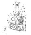
- the labeller according to the present invention is provided with a casing 10 having a bottom cover 60 and a handle 11 which extends from the rear of the casing.
- the labeller includes a drive mechanism 20 which is operable to drive a feed drum 30 which is provided in the casing 10.
- the labeller is further provided with a carrier strip feed mechanism 40 for feeding the carrier strip in cooperation with the feed drum, a printer unit 50 which is driven by the drive mechanism.
- the said casing 10 is provided, in addition to the handle 11, with a label tape holder 12 located at the upper part of the casing as shown in Figures 1 and 2.
- a slit 13 is formed in one side wall of the casing 10, generally the right hand side wall as viewed from the front.
- a label applicator such as a depression roller 14 is provided at the front part of the casing.
- the label tape holder 12 is constructed to be pivotable upwardly as shown in Figure 1.
- the label tape holder 12- may be rotated to the position shown with a broken line in Figure 1 while the roll of label tape 70 is placed on the label tape holder 12. It may then be returned to its operating position as shown with a solid line in Figure 1 once the roll of label tape 70 is in position.
- the label tape 70 can be held between both side walls of the,casing without falling off after the label tape holder 12 has been returned to the operating position.
- the slit 13 is provided by cutting off a part of one side wall of the casing 10 starting from a position near the label tape holder 12 and ending at a lower position to completely separate one side wall of the casing 10 into front part 15 and rear part 16.
- the drive mechanism 20 includes a lever 23 which is pivoted at one point 21.
- the lever is normally biassed away from the handle 11 by a reset spring 22 as shown in Figure 2 and is manually operable to be brought close to the handle 11.
- An operating part 24 extends into the casing from the lever 23.
- a driving member such as rack gear 25 is provided on said operating part 24.
- the drive mechanism 20 is constructed so that said rack gear 25 drives the feed drum 30 and said operating part 24 drives the printer unit 50, and this construction is same as that of conventionally known labellers.
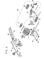
- the feed drum 30 incorporates a one-way clutch 31 as shown in Figure 3.
- This feed drum 30 is constructed so that the gear 32 coupled to this one-way clutch 31 is engaged with said rack gear 25 and the feed drum 30 is thus not rotated by movement of the lever 23 towards the handle but is rotated by a certain specified angle by the return motion of the lever 23.
- the feed drum 30 is provided with projection means 33 for engaging the carrier strip 71 of the label tape 70, a drive gear 34 for driving the carrier strip feed mechanism 40, etc. and a groove 35 provided in the periphery thereof.
- the drive gear 34 is coaxially mounted with the feed drum 30.
- the carrier strip feed mechanism 40 includes a label tape feed-in roller 41 which is forcibly depressed onto said feed drum 30, a feed-out roller 42 which is engaged with said drive gear 34, a first guide member 43 arranged between rollers 41 and 42 and a second guide member 44 at the discharging side to which said feed roller 42 is pivotally secured. Said feed-in and feed-out rollers 41 and 42 are rotated by the feed drum 30 and the drive gear 34 to forward the carrier strip 71 in the feed-out direction when the carrier strip 71 extended along the lower surface of said bottom cover 60 is inserted into the casing 10.
- said carrier strip 71 is fed out by the feed-out roller 42 from an opening between the handle 11 of the casing 10 and the lever 23 as will be described later.
- this construction can be made as desired as that of conventionally known labellers.
- said second guide member 44 is provided with a stripper 441 which is positioned in the groove 35 of the feed drum 30 as shown in Figure 2 to separate the carrier strip 71 from the feed drum 30.
- the printer unit 50 is mounted on the operating part 24 of said drive mechanism 20 and is lowered towards the label receiving surface 62 provided on said bottom cover 60 when the lever 23 is pivoted towards the handle 11, thus printing on the label 72 on the label receiving surface 62.
- the printer unit 50 has an ink applying mechanism such as, for example, an ink roller 51 which applies ink to type faces when it is lowered.
- this type of printer unit 50 is same as that of conventionally known labellers. For some types of labellers the printer unit may be omitted.
- the bottom cover 60 is constructed so that it is pivotally secured with the casing with the pivot point to the feed drum or handle side of said slit 13.
- the part of the bottom cover which is in use housed inside the casing 10 has a label tape receiving surface 61 opposing a pressure contacting part 81 of an impression member 80 described later and a label receiving surface 62 provided just below said printer unit 50.
- the free end of the cover adjacent the label receiving surface 62 forms a carrier strip turnback part 63.
- the impression member 80 is provided with a gear 82 which engages with said drive gear 34 and, for example, a cross-shaped multi-edged pressure contacting part 81 which comes in pressure contact with said label tape receiving surface 61 to make the label tape 70 come in pressure contact with the label tape receiving surface 61 by the tip of this pressure contacting part 81.
- the relationship between the tape receiving surface 61 and the pressure contact part 81 of said impression member 80 is such that the pressure contact part 81 is moved away from the tape receiving surface 61 when the feed drum 30 is rotated and the pressure contact part 81 depresses the label tape 70 onto the label tape receiving surface 61 when the feed drum 30 is stationary, and the label tape 70 is prevented from drifting whenever a label 72 is stuck to an article.
- Another construction can be selected as a label control means as described above.
- a spring member which is adapted to release the label tape in conjunction with the drive mechanism 20, only while the feed drum 30 is operating, can be used.
- the illustrated embodiment of the present invention is operated as described below.
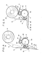
- the roll of label tape 70 is mounted by pivotally moving the tape holder 12 to the upright position as shown with the broken line in Figure 1 and in Figure 4.
- the bottom cover 60 is opened. Then the free end of said label tape 70 is drawn out downwardly and inserted into said slit 13 laterally and extended downwardly beyond the free end of the bottom cover 60 as shown with the solid line in Figure 4.
- said label tape 70 is housed in the casing 10 through the slit 13 and extended into the casing while keeping contact with the impression member 80 as shown with a broken line in Figure 4, and the lower end is suspended from the bottom cover 60 to the lower side.
- the carrier strip 71 is intermittently fed by reciprocating the lever 23 and the labels 72 can be peeled from the carrier strip 71 at the carrier strip turnback part 63 and forwarded as shown in Figure 5.
- the labeller according to the present invention is provided with the slit 13, which extends from the tape holder to the bottom cover, in one side wall of the casing 10 and the label tape 70 is initially positioned in the casing by inserting the label tape 70 laterally into this slit 13. Therefore, the labeller is advantageous in that a flexible long label tape 70 can be easily positioned in the casing 10 and turned back from the label tape turnback part 63 and extended by closing the bottom cover 60 since the label receiving surface 62 of the bottom cover 60 is aligned with the lower open end of said slit 13 when the bottom cover 60 is opened.
Landscapes
- Labeling Devices (AREA)
Applications Claiming Priority (2)
| Application Number | Priority Date | Filing Date | Title |
|---|---|---|---|
| JP1985011614U JPH018499Y2 (fr) | 1985-01-30 | 1985-01-30 | |
| JP11614/85 | 1985-01-30 |
Publications (3)
| Publication Number | Publication Date |
|---|---|
| EP0196744A2 true EP0196744A2 (fr) | 1986-10-08 |
| EP0196744A3 EP0196744A3 (en) | 1986-12-10 |
| EP0196744B1 EP0196744B1 (fr) | 1990-01-17 |
Family
ID=11782790
Family Applications (1)
| Application Number | Title | Priority Date | Filing Date |
|---|---|---|---|
| EP86300648A Expired - Lifetime EP0196744B1 (fr) | 1985-01-30 | 1986-01-30 | Etiqueteuse à main |
Country Status (8)
| Country | Link |
|---|---|
| US (1) | US4699685A (fr) |
| EP (1) | EP0196744B1 (fr) |
| JP (1) | JPH018499Y2 (fr) |
| KR (1) | KR890007376Y1 (fr) |
| AU (1) | AU561603B2 (fr) |
| BR (1) | BR6600051U (fr) |
| CA (1) | CA1272163A (fr) |
| DE (1) | DE3668297D1 (fr) |
Families Citing this family (22)
| Publication number | Priority date | Publication date | Assignee | Title |
|---|---|---|---|---|
| DE3706433A1 (de) * | 1987-02-27 | 1988-09-08 | Esselte Meto Int Gmbh | Handetikettiergeraet |
| DE3712963A1 (de) * | 1987-04-16 | 1988-11-03 | Hermann Klaus D | Handetikettiergeraet |
| DE3843068A1 (de) * | 1988-12-21 | 1990-06-28 | Esselte Meto Int Gmbh | Vorrichtung zum zufuehren eines etikettenbandes |
| US5254206A (en) * | 1992-01-31 | 1993-10-19 | Wing Donald B | Hand-held labeling device |
| US5535815A (en) * | 1995-05-24 | 1996-07-16 | The United States Of America As Represented By The Secretary Of The Navy | Package-interface thermal switch |
| US5921180A (en) * | 1997-02-05 | 1999-07-13 | Lee; Duck Hee | Label stamper with tape loading means, guide means, holding means, stamping means, and replaceable cartridge |
| US5935670A (en) * | 1997-02-06 | 1999-08-10 | All-Pak Sales, Inc. | Thermoplastic adhesive dispensing method and apparatus |
| US20030164220A1 (en) * | 1997-02-06 | 2003-09-04 | Downs John P. | Stand and pneumatic actuator for adhesive segment applicator apparatus |
| US20030118771A1 (en) * | 1997-02-06 | 2003-06-26 | Downs John P. | Roll of adhesive segments for use in an adhesive segment applicator apparatus and method of making the same |
| US7195049B2 (en) * | 1997-02-06 | 2007-03-27 | Glue Dots International, Llc | Handheld mechanical adhesive segment applicator apparatus and method |
| US7837815B2 (en) * | 1997-02-06 | 2010-11-23 | Glue Dots International Llc | Adhesive segment indexing method and apparatus and roll of adhesive segments for use therewith |
| US20050126692A1 (en) * | 2003-12-09 | 2005-06-16 | Hajny Roger V. | System and method for advancing thermoplastic adhesive segment dispensing tape and applying adhesive segments thereby |
| US8006734B2 (en) * | 2003-12-09 | 2011-08-30 | Glue Dots International Llc | System and method for advancing thermoplastic adhesive segment dispensing tape and applying adhesive segments thereby |
| US20080017323A1 (en) * | 2003-12-09 | 2008-01-24 | Peterson Burton J | Handheld adhesive applicator |
| US20050255275A1 (en) * | 2004-05-14 | 2005-11-17 | Downs John P | Adhesive dispensing tape including a transparent carrier material |
| US20060213620A1 (en) * | 2005-03-22 | 2006-09-28 | Kabushiki Sato | Label affixing machine having label roll core holding mechanism |
| US7900674B2 (en) * | 2007-05-08 | 2011-03-08 | Open Data S.R.L. | Labeling machine |
| JP2009274737A (ja) * | 2008-05-13 | 2009-11-26 | Sato Knowledge & Intellectual Property Institute | 携帯式ラベル貼付け機のラベル装填装置およびラベル装填方法 |
| IT1396267B1 (it) * | 2009-10-06 | 2012-11-16 | Open Data S R L | Etichettatrice. |
| JP5457243B2 (ja) * | 2010-03-24 | 2014-04-02 | サトーホールディングス株式会社 | 携帯式ラベル貼付け機のプラテンユニット開閉装置およびプラテンユニット開閉方法 |
| US8376015B2 (en) * | 2010-08-26 | 2013-02-19 | Checkpoint Systems, Inc. | Hand-held labeler with improved label roll lift mechanism |
| USD708666S1 (en) | 2011-11-18 | 2014-07-08 | Glue Dots International, Llc | Dispenser |
Citations (2)
| Publication number | Priority date | Publication date | Assignee | Title |
|---|---|---|---|---|
| DE2104419A1 (de) * | 1970-11-12 | 1972-05-18 | Dinter, Herbert, West Covina, Calif. (V.StA.) | Etikettiervorrichtung |
| GB2106864A (en) * | 1981-09-28 | 1983-04-20 | Shinsei Industries Co | Label dispensing device |
Family Cites Families (8)
| Publication number | Priority date | Publication date | Assignee | Title |
|---|---|---|---|---|
| NL113061C (fr) * | 1960-04-20 | |||
| US3156603A (en) * | 1962-01-02 | 1964-11-10 | Clifford C Robinson | Tape dispenser |
| US3231446A (en) * | 1962-11-07 | 1966-01-25 | Dennison Mfg Co | Device for printing labels |
| US4041863A (en) * | 1975-07-18 | 1977-08-16 | Vidac Corporation | Precision hand label imprinter and dispenser |
| BR7806014A (pt) * | 1977-09-19 | 1979-05-29 | Shinsei Industries Co | Etiquetadora manual |
| US4188255A (en) * | 1978-02-23 | 1980-02-12 | Tovel S.P.A. | Price labelling apparatus |
| AU536106B2 (en) * | 1980-10-24 | 1984-04-19 | K.K. Shinsei Industries | Labeler |
| JPS6160435A (ja) * | 1984-09-03 | 1986-03-28 | 株式会社 兼文 | 連続ラベル貼り機 |
-
1985
- 1985-01-30 JP JP1985011614U patent/JPH018499Y2/ja not_active Expired
-
1986
- 1986-01-09 KR KR2019860000122U patent/KR890007376Y1/ko not_active IP Right Cessation
- 1986-01-17 BR BR6600051U patent/BR6600051U/pt not_active IP Right Cessation
- 1986-01-22 CA CA000500076A patent/CA1272163A/fr not_active Expired - Lifetime
- 1986-01-24 AU AU52788/86A patent/AU561603B2/en not_active Ceased
- 1986-01-27 US US06/822,614 patent/US4699685A/en not_active Expired - Fee Related
- 1986-01-30 DE DE8686300648T patent/DE3668297D1/de not_active Expired - Fee Related
- 1986-01-30 EP EP86300648A patent/EP0196744B1/fr not_active Expired - Lifetime
Patent Citations (2)
| Publication number | Priority date | Publication date | Assignee | Title |
|---|---|---|---|---|
| DE2104419A1 (de) * | 1970-11-12 | 1972-05-18 | Dinter, Herbert, West Covina, Calif. (V.StA.) | Etikettiervorrichtung |
| GB2106864A (en) * | 1981-09-28 | 1983-04-20 | Shinsei Industries Co | Label dispensing device |
Also Published As
| Publication number | Publication date |
|---|---|
| CA1272163A (fr) | 1990-07-31 |
| AU5278886A (en) | 1986-09-11 |
| AU561603B2 (en) | 1987-05-14 |
| EP0196744A3 (en) | 1986-12-10 |
| KR860009697U (ko) | 1986-08-13 |
| DE3668297D1 (de) | 1990-02-22 |
| KR890007376Y1 (ko) | 1989-10-25 |
| JPH018499Y2 (fr) | 1989-03-07 |
| EP0196744B1 (fr) | 1990-01-17 |
| BR6600051U (pt) | 1987-09-22 |
| US4699685A (en) | 1987-10-13 |
| JPS61129711U (fr) | 1986-08-14 |
Similar Documents
| Publication | Publication Date | Title |
|---|---|---|
| EP0196744A2 (fr) | Etiqueteuse à main | |
| US4815875A (en) | Tape-ribbon cartridge and receiver tray with pivoted cover and cam | |
| EP0061776B1 (fr) | Dispositif pour imprimer et cassette y destinée | |
| US5056940A (en) | Thermal printing device and tape supply cartridge therefor | |
| US4815874A (en) | Thermal printer and tape-ribbon cartridge with cut-off mechanism | |
| US4917514A (en) | Thermal printing device and tape supply cartridge embodying a tape cut-off mechanism | |
| US4301729A (en) | Manually-operated labeler | |
| US7069972B1 (en) | Electronic tape dispenser | |
| US4832514A (en) | Thermal transfer device and tape-ribbon cartridge therefor | |
| US4930913A (en) | Thermal printing device and tape supply cartridge therefor | |
| US4176603A (en) | Label strip inserting device | |
| US3955711A (en) | Dispenser for self-stick strip-carried labels | |
| US20050121146A1 (en) | Label printer that dispenses labels in non-peel or automatic peel modes | |
| JPH0737256B2 (ja) | ラベルストリップ供給装置 | |
| EP1308251A2 (fr) | Mécanisme de coupe | |
| CA2355994C (fr) | Pistolet etiquetteur | |
| US4308797A (en) | Apparatus for printing or applying self-adhesive labels | |
| GB2234469A (en) | Facilitating insertion and removal of elongate printing substrates in selective printers | |
| EP0096764B1 (fr) | Machine à étiqueter portative | |
| US6382291B2 (en) | Dispenser for self-adhesive material | |
| US4377435A (en) | Labeler | |
| EP0759398B1 (fr) | Etiqueteuse à main | |
| US4518454A (en) | Manually-operated labeler | |
| EP1609723B1 (fr) | Outil d'etiquetage | |
| US4360399A (en) | Hand-held labeler and labeling method |
Legal Events
| Date | Code | Title | Description |
|---|---|---|---|
| PUAI | Public reference made under article 153(3) epc to a published international application that has entered the european phase |
Free format text: ORIGINAL CODE: 0009012 |
|
| AK | Designated contracting states |
Kind code of ref document: A2 Designated state(s): DE FR GB IT NL |
|
| PUAL | Search report despatched |
Free format text: ORIGINAL CODE: 0009013 |
|
| AK | Designated contracting states |
Kind code of ref document: A3 Designated state(s): DE FR GB IT NL |
|
| 17P | Request for examination filed |
Effective date: 19870323 |
|
| 17Q | First examination report despatched |
Effective date: 19880225 |
|
| GRAA | (expected) grant |
Free format text: ORIGINAL CODE: 0009210 |
|
| AK | Designated contracting states |
Kind code of ref document: B1 Designated state(s): DE FR GB IT NL |
|
| ITF | It: translation for a ep patent filed | ||
| REF | Corresponds to: |
Ref document number: 3668297 Country of ref document: DE Date of ref document: 19900222 |
|
| ET | Fr: translation filed | ||
| PLBE | No opposition filed within time limit |
Free format text: ORIGINAL CODE: 0009261 |
|
| STAA | Information on the status of an ep patent application or granted ep patent |
Free format text: STATUS: NO OPPOSITION FILED WITHIN TIME LIMIT |
|
| 26N | No opposition filed | ||
| ITTA | It: last paid annual fee | ||
| PGFP | Annual fee paid to national office [announced via postgrant information from national office to epo] |
Ref country code: GB Payment date: 19980121 Year of fee payment: 13 |
|
| PGFP | Annual fee paid to national office [announced via postgrant information from national office to epo] |
Ref country code: FR Payment date: 19980126 Year of fee payment: 13 |
|
| PGFP | Annual fee paid to national office [announced via postgrant information from national office to epo] |
Ref country code: NL Payment date: 19980130 Year of fee payment: 13 |
|
| PGFP | Annual fee paid to national office [announced via postgrant information from national office to epo] |
Ref country code: DE Payment date: 19980204 Year of fee payment: 13 |
|
| PG25 | Lapsed in a contracting state [announced via postgrant information from national office to epo] |
Ref country code: GB Free format text: LAPSE BECAUSE OF NON-PAYMENT OF DUE FEES Effective date: 19990130 |
|
| PG25 | Lapsed in a contracting state [announced via postgrant information from national office to epo] |
Ref country code: NL Free format text: LAPSE BECAUSE OF NON-PAYMENT OF DUE FEES Effective date: 19990801 |
|
| GBPC | Gb: european patent ceased through non-payment of renewal fee |
Effective date: 19990130 |
|
| PG25 | Lapsed in a contracting state [announced via postgrant information from national office to epo] |
Ref country code: FR Free format text: LAPSE BECAUSE OF NON-PAYMENT OF DUE FEES Effective date: 19990930 |
|
| PG25 | Lapsed in a contracting state [announced via postgrant information from national office to epo] |
Ref country code: DE Free format text: LAPSE BECAUSE OF NON-PAYMENT OF DUE FEES Effective date: 19991103 |
|
| REG | Reference to a national code |
Ref country code: FR Ref legal event code: ST |
|
| PG25 | Lapsed in a contracting state [announced via postgrant information from national office to epo] |
Ref country code: IT Free format text: LAPSE BECAUSE OF NON-PAYMENT OF DUE FEES;WARNING: LAPSES OF ITALIAN PATENTS WITH EFFECTIVE DATE BEFORE 2007 MAY HAVE OCCURRED AT ANY TIME BEFORE 2007. THE CORRECT EFFECTIVE DATE MAY BE DIFFERENT FROM THE ONE RECORDED. Effective date: 20050130 |