EP0195179B1 - Photomètre pour la mesure continue de concentrations - Google Patents
Photomètre pour la mesure continue de concentrations Download PDFInfo
- Publication number
- EP0195179B1 EP0195179B1 EP86100272A EP86100272A EP0195179B1 EP 0195179 B1 EP0195179 B1 EP 0195179B1 EP 86100272 A EP86100272 A EP 86100272A EP 86100272 A EP86100272 A EP 86100272A EP 0195179 B1 EP0195179 B1 EP 0195179B1
- Authority
- EP
- European Patent Office
- Prior art keywords
- gas
- chamber
- laser
- measurement
- amplifier
- Prior art date
- Legal status (The legal status is an assumption and is not a legal conclusion. Google has not performed a legal analysis and makes no representation as to the accuracy of the status listed.)
- Expired - Lifetime
Links
Images

Classifications
-
- G—PHYSICS
- G01—MEASURING; TESTING
- G01N—INVESTIGATING OR ANALYSING MATERIALS BY DETERMINING THEIR CHEMICAL OR PHYSICAL PROPERTIES
- G01N21/00—Investigating or analysing materials by the use of optical means, i.e. using sub-millimetre waves, infrared, visible or ultraviolet light
- G01N21/17—Systems in which incident light is modified in accordance with the properties of the material investigated
- G01N21/25—Colour; Spectral properties, i.e. comparison of effect of material on the light at two or more different wavelengths or wavelength bands
- G01N21/31—Investigating relative effect of material at wavelengths characteristic of specific elements or molecules, e.g. atomic absorption spectrometry
- G01N21/39—Investigating relative effect of material at wavelengths characteristic of specific elements or molecules, e.g. atomic absorption spectrometry using tunable lasers
Definitions
- the invention relates to a process photometer for the continuous measurement of the concentrations of infrared active gases according to the preamble of the claim.
- measurements of the HF concentration in water vapor-containing gases can also be carried out with high sensitivity if an HF laser is used as the radiation source.
- this method is associated with high investment costs (frequency stabilization) and is also very personnel-intensive and consequently cannot be used for process measurement technology.
- Diode lasers for the near infrared range (at 0, 8pm and at 1pm and 3pm) as well as lead salt lasers for the middle infrared range (above about 3pm) are already available (see OPTICAL ENGINEERING, Vol. 23, No. 1) , Jan-Feb 1989, S88-91).
- the economical use of lead salt lasers is not possible due to the high expenditure for frequency and power stabilization or for cooling.
- the diode lasers have been specially developed for optical message transmission.
- the object on which the invention was based was to design a process photometer of the type mentioned at the beginning in such a way that a physical HF measuring system suitable for process control is available, with which e.g. the HF producing industry is able to improve the product quality and the operational safety of the plants and to measure the HF emissions in waste incineration plants according to TA-Luft.
- HF has a single normal oscillation whose optical excitation (0-1) takes place at 2.5pm. Because of the pure line structure of the spectrum (FIG. 1), the sensitivities achievable with conventional filter photometers are too low for measurements in the ppm range, and there are also strong cross-sensitivities to water vapor. Measurements with gas filter correlation technology are not possible due to the strong absorption and desorption effects of HF on surfaces.
- the 1.0 harmonic of the HF absorption is 1.3pm and, in contrast to the HF fundamental at 2.4pm, does not overlap with the corresponding absorption bands of H 2 0. Furthermore, the absorption coefficient of the 1st harmonic is only about a factor of 8 smaller than the fundamental vibration. It is therefore possible to use the 1.3 pm diode laser (laser emission frequency 1284 nm) available for optical message transmission as the radiation source, so that, due to the high selectivity of these emitters, in principle higher sensitivities are achieved than with photometers with conventional light sources in the HF absorption range work at 2, 4pm (the latter - as already mentioned - because of their cross sensitivity to water, they are only suitable as HF measuring systems in a H 2 0 -free atmosphere).
- the semiconductor lasers (eg lnGaAsP / InP) generally show a multimode emission spectrum (FIG. 2), which can be influenced by suitable choice of the parameters so that the maximum intensity only occurs in one mode and the other emission frequencies are largely suppressed.
- FOG. 2 the operating temperature of the laser
- the laser can be tuned in a narrow range (approx. 20-30 nm) and brought into line with a line of the HF rotation oscillation spectrum.
- the HF concentration in a gas mixture can be determined by scanning an HF absorption line and determining the line integral or the maximum extinction. Because of the fact that the extinction coefficient is about 8 times smaller than that of the fundamental However, harmonics do not yet sufficiently meet the requirements for the measurement accuracy to be achieved.
- so-called derivative spectroscopy is used when measuring with the laser diodes.
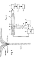
- the laser diode 1 (see Fig. 4) is operated with an alternating current superimposed on the direct current component.
- the output frequency (wavelength).
- the laser signal is detected via a lock-in amplifier 2 which lures to the modulation frequency f, a signal is obtained which corresponds to the 1st derivative of the absorption line.
- the detection is carried out at twice the modulation frequency (2f), the second derivative of the absorption line is obtained.
- the advantage of this method of measurement is the signal noise in the drastic reduction so that extinctions of 10- 5 are detectable by measuring arrangements of this kind. Measurement signals of this order of magnitude are also recorded with the HF laser diode photometer.
- the adjustment to the center of the line can be carried out by decoupling (beam splitter 6) a part (reference beam 3, see FIG. 4) of the laser radiation 5, which radiates through a reference cuvette 7, which contains the gas to be measured in a defined concentration, and then onto a second Detector 8 hits.
- the signal 24 of the first derivative formed in the lock-in amplifier 9 can be used in the zero crossing for exact wavelength adjustment 10 (laser current, temperature) of the laser 1.
- the sine generator 11 generates the laser beam frequency f.
- the measuring beam 12 passes through the measuring cell 13 and strikes the first detector 14 as an extinction signal, the output signal of which - as already described - is processed in the lock-in amplifier 2 to form the second derivative 2f. Its output signal 23 is sent to the computer 15, which calculates the measured value 16 (concentration).
- Measurements were carried out with an arrangement in which the laser 1 was tuned via the HF absorption line by temperature variation. The arrangement corresponded approximately to that shown in FIG. 4.
- the associated detector 8 was used to control the power of the laser diode 1.
- Semiconductor lasers have been used which are matched to the transitions R (0) -R (2) of the 0-2 transition of the HF molecule.
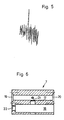
- For the HF measurement in the measuring cell 13, air was passed through about 4% hydrofluoric acid at room temperature and sucked through the measuring cell 13 (1 100 cm) under reduced pressure (approx. 100 mbar).
- a typical measurement signal is shown in FIG. 5.
- the high background is essentially caused by optical interference in the beam path (in particular at the beam splitter 6).
- the radiation 5 is decoupled via an optical fiber connection (pigtail).
- the beam splitting 6 in measuring and reference branch 12, 3 is carried out via a light guide branch module (distribution ratio 1: 1) with light guide connections, while the coupling of laser 1 and branch 6 via a light guide plug connection and the coupling of the laser beams 12, 3 from branching cables via Selfoc lenses to produce a parallel light beam.
- the Selfoc lenses are coated with an anti-reflective coating.
- the optimal modulation frequency for laser 1 is in the range of 10 kHz.
- the lock-in amplifiers 2, 9 can therefore be optimized to a single frequency f or 2f.
- a vector output is preferred as the measurement signal (phase-independent measurement).
- the 90 ° phase shifted signal must be recorded (zero crossing measurement).
- Both lock-in amplifiers 2, 9 are provided with offset compensation (this may also be possible in the measurement processing electronics (microprocessor)).
- the amplifiers 2, 9 are installed in a thermostated measuring cabinet.
- the power regulation of the laser diode 1 is usually controlled via the signal of the monitor diode integrated in the laser housing. However, it is possible that with this method, especially when the laser temperature is varied, insufficient stability is achieved. Alternatively, power is controlled via the output signal of the measuring detector 14 (bypassing the lock-in amplifier 2) without Emp loss of sensitivity for the measurement signal.
- This method has the advantage that changes in the optical transmission properties in the entire measuring branch do not have an effect in the lock-in amplifier 2. This is particularly important if the monitor diode detects other mode components of the laser radiation than the measuring detectors 8, 14.
- the power control of the laser diode 1 must relate to both the DC power and the AC power, so that a constant degree of modulation always occurs Laser radiation is guaranteed.
- the receiver diodes in the detectors 8, 14 are stabilized by temperature stabilization using Peltier systems.
- the AC and DC power of the laser 1 are fixed.
- the offset correction of the lock-in amplifiers 2, 9 must be carried out at a suitable time during the scanning. This measure must be repeated at predetermined intervals. This can e.g. via a defined detuning of the laser frequency from the HF absorption and subsequent adjustment to the center of the line.
Landscapes
- Physics & Mathematics (AREA)
- Spectroscopy & Molecular Physics (AREA)
- Analytical Chemistry (AREA)
- Health & Medical Sciences (AREA)
- Life Sciences & Earth Sciences (AREA)
- Chemical & Material Sciences (AREA)
- Optics & Photonics (AREA)
- Biochemistry (AREA)
- General Health & Medical Sciences (AREA)
- General Physics & Mathematics (AREA)
- Immunology (AREA)
- Pathology (AREA)
- Investigating Or Analysing Materials By Optical Means (AREA)
Claims (1)
Priority Applications (1)
| Application Number | Priority Date | Filing Date | Title |
|---|---|---|---|
| AT86100272T ATE53124T1 (de) | 1985-03-20 | 1986-01-10 | Prozessphotometer zur kontinuierlichen messung von konzentrationen. |
Applications Claiming Priority (2)
| Application Number | Priority Date | Filing Date | Title |
|---|---|---|---|
| DE19853510052 DE3510052A1 (de) | 1985-03-20 | 1985-03-20 | Verfahren und prozessphotometer zur kontinuierlichen messung von konzentrationen |
| DE3510052 | 1985-03-20 |
Publications (2)
| Publication Number | Publication Date |
|---|---|
| EP0195179A1 EP0195179A1 (fr) | 1986-09-24 |
| EP0195179B1 true EP0195179B1 (fr) | 1990-05-23 |
Family
ID=6265792
Family Applications (1)
| Application Number | Title | Priority Date | Filing Date |
|---|---|---|---|
| EP86100272A Expired - Lifetime EP0195179B1 (fr) | 1985-03-20 | 1986-01-10 | Photomètre pour la mesure continue de concentrations |
Country Status (3)
| Country | Link |
|---|---|
| EP (1) | EP0195179B1 (fr) |
| AT (1) | ATE53124T1 (fr) |
| DE (1) | DE3510052A1 (fr) |
Cited By (1)
| Publication number | Priority date | Publication date | Assignee | Title |
|---|---|---|---|---|
| CN109374552A (zh) * | 2018-11-23 | 2019-02-22 | 国家海洋局第二海洋研究所 | 一种基于分段光路的水体吸收系数测量装置 |
Families Citing this family (17)
| Publication number | Priority date | Publication date | Assignee | Title |
|---|---|---|---|---|
| DE3633931A1 (de) * | 1986-10-04 | 1988-04-07 | Kernforschungsz Karlsruhe | Verfahren und einrichtung zur kontinuierlichen messung der konzentration eines gasbestandteiles |
| FR2655781A1 (fr) * | 1989-12-08 | 1991-06-14 | Oscilloquartz Sa | Circuit de stabilisation de la frequence d'emission d'une diode laser et diode laser stabilisee. |
| DE4000583A1 (de) * | 1990-01-10 | 1991-07-11 | Muetek Gmbh | Verfahren zum betreiben eines strahlungsabsorptionsspektrometers |
| US5202570A (en) * | 1990-03-27 | 1993-04-13 | Tokyo Gas Co., Ltd. | Gas detection device |
| EP0629851A3 (fr) * | 1993-06-17 | 1995-03-22 | Fraunhofer Ges Forschung | Dispositif pour analyse de traces de gaz par spectroscopie d'absorption. |
| DE4333422C1 (de) * | 1993-09-30 | 1995-03-02 | Fraunhofer Ges Forschung | Verfahren und Anordnung zur Bestimmung und Normierung der Intensität eines Meßsignals, insbesondere bei der Modulations-Laser-Absorptionsspektroskopie |
| DE4446723C2 (de) * | 1994-06-29 | 1997-03-13 | Hermann Prof Dr Harde | Vorrichtung und Verfahren zur Messung der Konzentration eines Gases |
| DE19518983A1 (de) * | 1995-05-29 | 1996-12-05 | Mueller Wolf Ruediger Dr Ing | Verfahren und Vorrichtung zur Bestimmung der biologischen Abbaubarkeit in wässrigen Lösungen unter anaeroben Bedingungen |
| DE19525415C2 (de) * | 1995-07-12 | 1997-11-27 | Optikzentrum Nrw Gmbh Oz | Verfahren und Vorrichtung zur Bestimmung der Wasserdampfkonzentration bzw. des Taupunktes |
| WO2000040949A1 (fr) * | 1999-01-06 | 2000-07-13 | Georgy Georgevich Tertyshny | Procede d'analyse d'objets physiques et dispositif de mise en oeuvre de ce procede |
| DE10020615C2 (de) * | 2000-04-27 | 2002-02-28 | Glukomeditech Ag | Verfahren zur langzeitstabilen und gut reproduzierbaren spektrometrischen Messung der Konzentrationen der Bestandteile wässriger Lösungen sowie Vorrichtung zur Durchführung dieses Verfahrens |
| DE10031674A1 (de) * | 2000-06-29 | 2002-01-17 | Siemens Ag | Verfahren zur Brennwertbestimmung von Erdgas |
| DE10316685A1 (de) | 2003-04-10 | 2004-10-28 | Endress + Hauser Conducta Gesellschaft für Mess- und Regeltechnik mbH + Co. KG | Vorichtung zur photometrischen Messung der Konzentration einer chemischen Substanz in einer Meßlösung |
| DE102007032849A1 (de) * | 2007-03-16 | 2008-09-18 | Biocomfort Diagnostics Gmbh | Messeinrichtung und Verfahren zur optischen Konzentrationsbestimmung von Blutzucker und/oder Laktat in biologischen Systemen |
| ATE453112T1 (de) * | 2007-05-09 | 2010-01-15 | Sick Maihak Gmbh | Küvette |
| WO2008147994A1 (fr) * | 2007-05-24 | 2008-12-04 | Zolo Technologies, Inc. | Coffrage et tomographie pour des mesures de température et de concentration d'espèces de résolution spatiale élevée |
| CN105259137A (zh) * | 2015-11-04 | 2016-01-20 | 安徽中科智泰光电测控科技有限公司 | 一种管道氨逃逸激光吸收光谱自动在线原位测量装置 |
Family Cites Families (3)
| Publication number | Priority date | Publication date | Assignee | Title |
|---|---|---|---|---|
| US3805074A (en) * | 1973-01-02 | 1974-04-16 | Texas Instruments Inc | Spectral scan air monitor |
| DE2635171C3 (de) * | 1976-08-05 | 1980-06-19 | 6000 Frankfurt | Gerät zur Bestimmung der Konzentration eines Bestandteils einer Gasprobe |
| CA1179861A (fr) * | 1981-04-13 | 1984-12-27 | Australian Atomic Energy Commission | Methode et appareil pour mesurer la concentration d'acide fluorhydrique gazeux |
-
1985
- 1985-03-20 DE DE19853510052 patent/DE3510052A1/de active Granted
-
1986
- 1986-01-10 EP EP86100272A patent/EP0195179B1/fr not_active Expired - Lifetime
- 1986-01-10 AT AT86100272T patent/ATE53124T1/de not_active IP Right Cessation
Cited By (1)
| Publication number | Priority date | Publication date | Assignee | Title |
|---|---|---|---|---|
| CN109374552A (zh) * | 2018-11-23 | 2019-02-22 | 国家海洋局第二海洋研究所 | 一种基于分段光路的水体吸收系数测量装置 |
Also Published As
| Publication number | Publication date |
|---|---|
| DE3510052C2 (fr) | 1991-09-19 |
| ATE53124T1 (de) | 1990-06-15 |
| EP0195179A1 (fr) | 1986-09-24 |
| DE3510052A1 (de) | 1986-09-25 |
Similar Documents
| Publication | Publication Date | Title |
|---|---|---|
| EP0195179B1 (fr) | Photomètre pour la mesure continue de concentrations | |
| DE69828569T2 (de) | Verfahren zum Messen der Konzentration von Wasserstoffperoxiddampf | |
| DE19840345B4 (de) | Verfahren und Vorrichtung zum quantitativen Aufspüren eines vorgegebenen Gases | |
| EP0263931B1 (fr) | Procédé et dispositif pour la mesure continue de la concentration d'un composant d'un gaz | |
| US7864323B2 (en) | Method for measuring the concentration of a gas component in a measuring gas | |
| EP0512238A1 (fr) | Procédé pour mesurer la teneur totale en carbone organique et en azote de l'eau | |
| DE4110095C2 (de) | Verfahren zur gasspektroskopischen Messung der Konzentration eines Gasbestandteiles | |
| EP2142909B1 (fr) | Système de détecteur pour analyseur de gaz à infrarouge non dispersif et procédé de détection d'un composant gazeux à mesurer dans un mélange de gaz au moyen d'un tel analyseur de gaz | |
| EP0677733A1 (fr) | Laser à gaz et détection de gaz avec celui-ci | |
| DE19853049C2 (de) | Vorrichtung und Verfahren zum Feststellen eines Lecks sowie Verwendung einer solchen Vorrichtung für die Lecksuche | |
| EP1183523A1 (fr) | Appareil d'analyse | |
| DE4122572A1 (de) | Verfahren zum betrieb einer laserdiode | |
| DE4231620A1 (de) | Vorrichtung zur Messung des Gesamtgehaltes an organischem Kohlenstoff und an Stickstoff in Wasser | |
| DE3116344C2 (fr) | ||
| DE3819531A1 (de) | Signalprozess- und betriebstechnik zur laserspektroskopischen mengenbestimmung von ammoniak in gasgemischen | |
| DE3508027A1 (de) | Verfahren und einrichtung zum ermitteln der konzentration oder der massenanteile bestimmter gase in gasmischungen | |
| KR100316487B1 (ko) | 가스중의 불순물의 분광분석방법 | |
| DE19521362A1 (de) | Messzelle für einen Wasserdampfsensor | |
| EP3771900B1 (fr) | Procédé de détermination d'une concentration en gaz et appareil de mesure | |
| JP2002131228A (ja) | レーザ分光分析方法 | |
| EP1430289A1 (fr) | Procede de spectroscopie a absorption laser et equipements correspondants | |
| DE19525415C2 (de) | Verfahren und Vorrichtung zur Bestimmung der Wasserdampfkonzentration bzw. des Taupunktes | |
| EP1370832B1 (fr) | Procede et dispositif permettant de detecter les effets de dispersion sur une mesure | |
| EP0629851A2 (fr) | Dispositif pour analyse de traces de gaz par spectroscopie d'absorption | |
| DE69925284T2 (de) | Spektroskopisches Verfahren zur Messung von Verunreinigungspuren in einem Gas mittels Laserstrahlung |
Legal Events
| Date | Code | Title | Description |
|---|---|---|---|
| PUAI | Public reference made under article 153(3) epc to a published international application that has entered the european phase |
Free format text: ORIGINAL CODE: 0009012 |
|
| AK | Designated contracting states |
Kind code of ref document: A1 Designated state(s): AT BE CH FR GB IT LI NL SE |
|
| 17P | Request for examination filed |
Effective date: 19861004 |
|
| 17Q | First examination report despatched |
Effective date: 19880301 |
|
| ITF | It: translation for a ep patent filed |
Owner name: DE DOMINICIS & MAYER S.R.L. |
|
| GRAA | (expected) grant |
Free format text: ORIGINAL CODE: 0009210 |
|
| AK | Designated contracting states |
Kind code of ref document: B1 Designated state(s): AT BE CH FR GB IT LI NL SE |
|
| REF | Corresponds to: |
Ref document number: 53124 Country of ref document: AT Date of ref document: 19900615 Kind code of ref document: T |
|
| ET | Fr: translation filed | ||
| GBT | Gb: translation of ep patent filed (gb section 77(6)(a)/1977) | ||
| ITTA | It: last paid annual fee | ||
| PLBE | No opposition filed within time limit |
Free format text: ORIGINAL CODE: 0009261 |
|
| STAA | Information on the status of an ep patent application or granted ep patent |
Free format text: STATUS: NO OPPOSITION FILED WITHIN TIME LIMIT |
|
| 26N | No opposition filed | ||
| PGFP | Annual fee paid to national office [announced via postgrant information from national office to epo] |
Ref country code: BE Payment date: 19930125 Year of fee payment: 8 |
|
| PGFP | Annual fee paid to national office [announced via postgrant information from national office to epo] |
Ref country code: CH Payment date: 19931129 Year of fee payment: 9 |
|
| PGFP | Annual fee paid to national office [announced via postgrant information from national office to epo] |
Ref country code: GB Payment date: 19931210 Year of fee payment: 9 |
|
| PGFP | Annual fee paid to national office [announced via postgrant information from national office to epo] |
Ref country code: SE Payment date: 19940118 Year of fee payment: 9 |
|
| PGFP | Annual fee paid to national office [announced via postgrant information from national office to epo] |
Ref country code: AT Payment date: 19940128 Year of fee payment: 9 |
|
| PG25 | Lapsed in a contracting state [announced via postgrant information from national office to epo] |
Ref country code: BE Effective date: 19940131 |
|
| PGFP | Annual fee paid to national office [announced via postgrant information from national office to epo] |
Ref country code: NL Payment date: 19940131 Year of fee payment: 9 |
|
| BERE | Be: lapsed |
Owner name: KERNFORSCHUNGSZENTRUM KARLSRUHE G.M.B.H. Effective date: 19940131 |
|
| PG25 | Lapsed in a contracting state [announced via postgrant information from national office to epo] |
Ref country code: GB Effective date: 19950110 Ref country code: AT Effective date: 19950110 |
|
| PG25 | Lapsed in a contracting state [announced via postgrant information from national office to epo] |
Ref country code: SE Effective date: 19950111 |
|
| EAL | Se: european patent in force in sweden |
Ref document number: 86100272.3 |
|
| PG25 | Lapsed in a contracting state [announced via postgrant information from national office to epo] |
Ref country code: LI Effective date: 19950131 Ref country code: CH Effective date: 19950131 |
|
| PG25 | Lapsed in a contracting state [announced via postgrant information from national office to epo] |
Ref country code: NL Effective date: 19950801 |
|
| GBPC | Gb: european patent ceased through non-payment of renewal fee |
Effective date: 19950110 |
|
| REG | Reference to a national code |
Ref country code: CH Ref legal event code: PL |
|
| NLV4 | Nl: lapsed or anulled due to non-payment of the annual fee |
Effective date: 19950801 |
|
| EUG | Se: european patent has lapsed |
Ref document number: 86100272.3 |
|
| REG | Reference to a national code |
Ref country code: FR Ref legal event code: TP |
|
| PGFP | Annual fee paid to national office [announced via postgrant information from national office to epo] |
Ref country code: FR Payment date: 20041230 Year of fee payment: 20 |
|
| PG25 | Lapsed in a contracting state [announced via postgrant information from national office to epo] |
Ref country code: IT Free format text: LAPSE BECAUSE OF NON-PAYMENT OF DUE FEES;WARNING: LAPSES OF ITALIAN PATENTS WITH EFFECTIVE DATE BEFORE 2007 MAY HAVE OCCURRED AT ANY TIME BEFORE 2007. THE CORRECT EFFECTIVE DATE MAY BE DIFFERENT FROM THE ONE RECORDED. Effective date: 20050110 |