EP0194990A2 - Vorrichtung zum Festklemmen eines Verschleisselementes für den Schieberverschluss eines metallurgischen Behälters - Google Patents
Vorrichtung zum Festklemmen eines Verschleisselementes für den Schieberverschluss eines metallurgischen Behälters Download PDFInfo
- Publication number
- EP0194990A2 EP0194990A2 EP86870035A EP86870035A EP0194990A2 EP 0194990 A2 EP0194990 A2 EP 0194990A2 EP 86870035 A EP86870035 A EP 86870035A EP 86870035 A EP86870035 A EP 86870035A EP 0194990 A2 EP0194990 A2 EP 0194990A2
- Authority
- EP
- European Patent Office
- Prior art keywords
- frame
- plate
- rotation
- axis
- cam
- Prior art date
- Legal status (The legal status is an assumption and is not a legal conclusion. Google has not performed a legal analysis and makes no representation as to the accuracy of the status listed.)
- Granted
Links
Images


Classifications
-
- B—PERFORMING OPERATIONS; TRANSPORTING
- B22—CASTING; POWDER METALLURGY
- B22D—CASTING OF METALS; CASTING OF OTHER SUBSTANCES BY THE SAME PROCESSES OR DEVICES
- B22D41/00—Casting melt-holding vessels, e.g. ladles, tundishes, cups or the like
- B22D41/14—Closures
- B22D41/22—Closures sliding-gate type, i.e. having a fixed plate and a movable plate in sliding contact with each other for selective registry of their openings
- B22D41/28—Plates therefor
- B22D41/34—Supporting, fixing or centering means therefor
Definitions
- the present invention relates to a device for clamping a wear element of a sliding closure of a metallurgical container intended for controlling the flow rate of molten metal, consisting of a refractory material possibly surrounded by a metal frame, mounted in a metal frame provided with a bottom wall and lateral stops against which bears at least one wear element.
- the wear elements essentially an internal nozzle ensuring the connection between the metallurgical container and the sliding closure, an upper fixed plate pierced with at least one orifice opposite the internal nozzle, a sliding plate provided with at least one sliding orifice joined against the fixed plate, possibly a lower fixed plate and a collecting nozzle.
- These wear elements are made of refractory material surrounded at least partially by a jacket forming a lost formwork. These elements provided with their metal frame are clamped in a support frame.
- the plates must generally be applied against a bottom formed in the associated metal frame.
- Known devices do not provide for pushing the plate against the bottom of the frame, an operation generally carried out manually or by pressing during the sliding closure. This process presents the double danger of introducing a human factor and of delaying this setting up action beyond the time of sintering of the grouts ensuring the joints.
- the present invention aims to remedy the drawbacks described above and proposes a device which makes it possible simultaneously to clamp the plate against the bottom of the frame, to absorb the clearances between the plate and the lateral stops and to wedge the plate in the frame, while avoiding the use of fasteners.
- a sliding closure device for a metallurgical container in particular a distributor containing a metal bath, essentially characterized in that it consists of a rotary member driving in rotation a cam having an inclined face which repels a face of a wear element based on a substantially parallel flange of the frame opposite the bottom thereof so as to simultaneously press the plate possibly provided with a frame against the bottom of the frame, the clamping of the plate against the lateral stops and the wedging of the plate in the frame .
- the clamping device has at each end of the central part of the rotary member forming a cam two coaxial pivot axes.
- the device is mounted in a housing delimited by the frame, in the walls are formed two circular cylindrical orifices coaxial on an axis perpendicular to the bottom of the frame, the large orifice possibly open on the side of the bottom of the frame being intended to receive the large pivot axis to which it serves as a rotation bearing, the small orifice situated on the opposite side with respect to the bottom of the frame having a diameter slightly greater than that of the small pivot axis to which it takes place rotation bearing, the bottom wall of the housing perpendicular to the axis of rotation of the rotary lock being determined with a view to serving as an axial stop for the bearing face of the rotary lock.
- the cam advantageously has the shape of a helix coaxial with the pivot axes, a flat being formed on the generator cylinder of the propeller in order to allow the introduction of the plate into the frame when the flat is brought opposite the plate.
- the preferred form is that of a helix with an axis parallel to the axis of rotation of the rotary bolt, the axis of the propeller being eccentric relative to the axis of rotation of the rotary lock.
- the device can include several clamping devices distributed around the periphery of the plate.
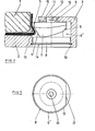
- FIG. 1 shows a metal frame, generally designated by the reference notation 1.
- This frame has a bottom wall 2 and lateral flanges 3. It encloses a wear element 4 of a sliding closure for metallurgical container.
- the wear element is usually a plate of refractory material possibly surrounded by a metal jacket 5.
- the lateral flange 3 of the frame 1 consists of an angle folded at a right angle intended to reinforce the rigidity of the frame. In the vicinity of opposite corners, there are provided cavities intended to each accommodate a clamping device 6.
- the wear element consisting of a plate 4 is tightened in frame 1 by the rotary lock 3.
- the sliding closure is then in the form of a set of parts nested one inside the other. and wedged by a rotary member locking the plate between the inclined face of the cam 7 and the bottom 2 of the frame 1.
- the plate 4 wedges the rotary lock between the parallel inclined face of the bearing surface 16 of the plate and the bottom 15 of housing 6 '.
- the size of the clamping device is very reduced both in thickness and in diameter, which makes it easy to accommodate it in existing devices.
- the rotary bolt 6 must exert on the bearing surface 13 of the plate 1 forces directed simultaneously towards the bottom 2 of the frame 2 and towards the center of the plate 4.
- two effects can be used independently or in combination to achieve this result.
- the cam 7 has the shape of a helix coaxial with the pivot axes 8, 9.
- the rotation of the rotary lock 3 causes a movement of the place of contact of the cam 7 with the bearing surface 13 towards the bottom 12 of the frame parallel to the axis of rotation of the rotary lock 6.
- the rotation of the rotary bolt 6 causes the displacement of the contact point of the cam 7 and of the bearing surface 13 towards the center of the plate. Pressing one against the other along inclined contact faces, of the cam 7 and of the frame 5 guarantees double tightening towards the bottom 2 of the frame 2 and towards the center of the plate.
- the cam 7 has the shape of a propeller whose axis is parallel but slightly eccentric relative to the axis of rotation of the rotary bolt 3. This device uses in combination the two propeller and eccentric effects previously described.
- the new closure device provides significant advantages in terms of robustness, production cost, size and reliability.
- the rotary lock is massive and can advantageously be made in one piece from the cast metal.
- Figure 1 shows two clamping devices 6 arranged in the frame 2, diametrically opposite with respect to the plate in a direction spaced less than 30 ° from the axis of the movement of the sliding closure. Such a device makes it possible to uniformly tighten the plate 4 against the bottom 2 of the frame 1.
- bearing surface 13 can be provided on any other part of the plate 4 and have various shapes provided that it has an inclined face opposite the side opposite the bottom 2 of the frame 1.
- a similar device can be provided in the large pivot axis 8, in particular in the case where accessibility on the bottom side of the frame proves more advantageous.
- the large pivot axis 8 is provided with a handle in order to produce rotation.
- Similar handles can be attached to the small pivot axis 9 provided that they do not have any interaction with the opposite parts of the plate 4 during the operations of the sliding closure.
Landscapes
- Engineering & Computer Science (AREA)
- Mechanical Engineering (AREA)
- Casting Support Devices, Ladles, And Melt Control Thereby (AREA)
- Clamps And Clips (AREA)
Applications Claiming Priority (2)
| Application Number | Priority Date | Filing Date | Title |
|---|---|---|---|
| BE214655 | 1985-03-15 | ||
| BE0/214655A BE901948A (fr) | 1985-03-15 | 1985-03-15 | Dispositif de serrage d'un element d'usure d'une fermeture coulissante de conteneur metallurgique. |
Publications (3)
| Publication Number | Publication Date |
|---|---|
| EP0194990A2 true EP0194990A2 (de) | 1986-09-17 |
| EP0194990A3 EP0194990A3 (en) | 1987-05-20 |
| EP0194990B1 EP0194990B1 (de) | 1990-10-03 |
Family
ID=3843863
Family Applications (1)
| Application Number | Title | Priority Date | Filing Date |
|---|---|---|---|
| EP86870035A Expired - Lifetime EP0194990B1 (de) | 1985-03-15 | 1986-03-13 | Vorrichtung zum Festklemmen eines Verschleisselementes für den Schieberverschluss eines metallurgischen Behälters |
Country Status (5)
| Country | Link |
|---|---|
| US (1) | US4687186A (de) |
| EP (1) | EP0194990B1 (de) |
| BE (1) | BE901948A (de) |
| DE (1) | DE3674608D1 (de) |
| ES (1) | ES8701558A1 (de) |
Cited By (5)
| Publication number | Priority date | Publication date | Assignee | Title |
|---|---|---|---|---|
| BE1001580A3 (fr) * | 1987-08-26 | 1989-12-12 | Shinagawa Refractories Co | Appareil de blocage et de fixation d'une plaque en refractaire pour un robinet valve de distribution pour controler le flux d'acier en fusion. |
| TR24929A (tr) * | 1991-03-11 | 1992-07-01 | Cerafer Sarl | METALURJIK KAPLARA AIT SüRGüLü KAPAKLARIN SüRGü PLAKASI |
| EP0498915A1 (de) * | 1990-01-30 | 1992-08-19 | Cerafer S.A.R.L. | Schieberplatte für Schieberverschlüsse von metallurgischen Gefässen |
| FR2740368A1 (fr) * | 1995-10-27 | 1997-04-30 | Vesuvius France Sa | Procede de reutilisation de plaques de fermeture a tiroir et plaque pour cette fermeture |
| WO1998042461A1 (en) * | 1997-03-26 | 1998-10-01 | Georg Fischer Disa A/S | Arrangement in foundry equipment comprising e.g. a moulding mac hine and a conveyor for 'green' sand moulds |
Families Citing this family (7)
| Publication number | Priority date | Publication date | Assignee | Title |
|---|---|---|---|---|
| EP0222070A1 (de) * | 1985-10-30 | 1987-05-20 | Didier S.A. | Einrichtung für Tragrahmen feuerfester Platten in Schieberverschlüssen |
| CH675976A5 (de) * | 1988-01-15 | 1990-11-30 | Stopinc Ag | |
| US5139237A (en) * | 1988-01-15 | 1992-08-18 | Stopinc Ag | Metal member with annular centering surface |
| BE1005987A3 (fr) * | 1992-06-16 | 1994-04-12 | Int Ind Eng Sa | Dispositif de regulation d'un debit de coulee. |
| CN1078114C (zh) * | 1996-08-05 | 2002-01-23 | 斯托品克股份公司 | 用于在含有熔融金属的容器的出口处的滑动闸阀的耐火板和夹持装置 |
| CA2444975C (en) * | 2001-05-01 | 2007-10-23 | Krosakiharima Corporation | Sliding nozzle unit |
| CH710094A2 (de) * | 2014-09-11 | 2016-03-15 | Refractory Intellectual Prop | Schiebeverschluss für ein metallurgisches Gefäss. |
Citations (3)
| Publication number | Priority date | Publication date | Assignee | Title |
|---|---|---|---|---|
| FR2100833A3 (de) * | 1970-06-27 | 1972-03-24 | Interstop Ag | |
| DE2732094A1 (de) * | 1977-07-15 | 1979-01-18 | Didier Werke Ag | Schiebeverschluss fuer metallschmelze enthaltende gefaesse |
| FR2528741A1 (fr) * | 1982-06-22 | 1983-12-23 | Didier Werke Ag | Appareil de serrage d'une plaque de fermeture sur une fermeture a coulisse d'un orifice de coulee sur un reservoir contenant un bain de fusion |
Family Cites Families (2)
| Publication number | Priority date | Publication date | Assignee | Title |
|---|---|---|---|---|
| DE2821839B2 (de) * | 1978-05-19 | 1981-04-16 | Stopine AG, Zug | Schiebeverschluß für den Ausguß an Metallschmelze enthaltenden Behältern |
| DE8013402U1 (de) * | 1980-05-17 | 1980-08-21 | Martin & Pagenstecher Gmbh, 5000 Koeln | Schieberplatte fuer schieberverschluesse |
-
1985
- 1985-03-15 BE BE0/214655A patent/BE901948A/fr not_active IP Right Cessation
-
1986
- 1986-03-12 ES ES552906A patent/ES8701558A1/es not_active Expired
- 1986-03-13 EP EP86870035A patent/EP0194990B1/de not_active Expired - Lifetime
- 1986-03-13 DE DE8686870035T patent/DE3674608D1/de not_active Expired - Fee Related
- 1986-03-17 US US06/840,266 patent/US4687186A/en not_active Expired - Fee Related
Patent Citations (3)
| Publication number | Priority date | Publication date | Assignee | Title |
|---|---|---|---|---|
| FR2100833A3 (de) * | 1970-06-27 | 1972-03-24 | Interstop Ag | |
| DE2732094A1 (de) * | 1977-07-15 | 1979-01-18 | Didier Werke Ag | Schiebeverschluss fuer metallschmelze enthaltende gefaesse |
| FR2528741A1 (fr) * | 1982-06-22 | 1983-12-23 | Didier Werke Ag | Appareil de serrage d'une plaque de fermeture sur une fermeture a coulisse d'un orifice de coulee sur un reservoir contenant un bain de fusion |
Cited By (7)
| Publication number | Priority date | Publication date | Assignee | Title |
|---|---|---|---|---|
| BE1001580A3 (fr) * | 1987-08-26 | 1989-12-12 | Shinagawa Refractories Co | Appareil de blocage et de fixation d'une plaque en refractaire pour un robinet valve de distribution pour controler le flux d'acier en fusion. |
| EP0498915A1 (de) * | 1990-01-30 | 1992-08-19 | Cerafer S.A.R.L. | Schieberplatte für Schieberverschlüsse von metallurgischen Gefässen |
| TR24929A (tr) * | 1991-03-11 | 1992-07-01 | Cerafer Sarl | METALURJIK KAPLARA AIT SüRGüLü KAPAKLARIN SüRGü PLAKASI |
| FR2740368A1 (fr) * | 1995-10-27 | 1997-04-30 | Vesuvius France Sa | Procede de reutilisation de plaques de fermeture a tiroir et plaque pour cette fermeture |
| WO1997015410A1 (en) * | 1995-10-27 | 1997-05-01 | Vesuvius France S.A. | Process for reusing slide gate plates and plate for this closure |
| EP1103326A1 (de) * | 1995-10-27 | 2001-05-30 | Vesuvius France (S.A.) | Platte für einen Schieberverschluss |
| WO1998042461A1 (en) * | 1997-03-26 | 1998-10-01 | Georg Fischer Disa A/S | Arrangement in foundry equipment comprising e.g. a moulding mac hine and a conveyor for 'green' sand moulds |
Also Published As
| Publication number | Publication date |
|---|---|
| US4687186A (en) | 1987-08-18 |
| ES8701558A1 (es) | 1986-12-16 |
| DE3674608D1 (de) | 1990-11-08 |
| EP0194990A3 (en) | 1987-05-20 |
| BE901948A (fr) | 1985-09-16 |
| ES552906A0 (es) | 1986-12-16 |
| EP0194990B1 (de) | 1990-10-03 |
Similar Documents
| Publication | Publication Date | Title |
|---|---|---|
| EP0194990B1 (de) | Vorrichtung zum Festklemmen eines Verschleisselementes für den Schieberverschluss eines metallurgischen Behälters | |
| EP1662052B1 (de) | Einrichtung zur Verriegelung eines Deckels auf einem Rahmen | |
| LU85957A1 (fr) | Plaque refractaire et buse de coulee,et procede de montage de plaques refractaires dans une vanne coulissante | |
| WO2006114538A1 (fr) | Procede et dispositif de liaison entre une piece d'usure et son support mis en jeu sur les equipements de manutention de materiaux par les engins de travaux publics | |
| CA2438350C (fr) | Dispositif de liaison amovible entre deux elements | |
| FR2756854A1 (fr) | Dispositif et procede pour tenir une lame de niveleuse | |
| FR2659571A1 (fr) | Broyeur a machoires. | |
| EP0611715B1 (de) | Lager zur Aufnahme eines Endes einer Wickelwelle zum Auf- oder Abwickeln von Werkstoffbahnen | |
| FR2640336A1 (fr) | Ecrou rapide | |
| EP2344390A1 (de) | Mit einer verriegelungsvorrichtung ausgestattetes werkzeug mit angelenkten komponenten | |
| EP0469939A2 (de) | Vorrichtung zum Verbinden zweier Gegenstände mit mehreren Befestigungspunkten | |
| FR2699583A1 (fr) | Porte à verrouillage mécanique étanche pour caveaux funéraires. | |
| FR2944542A1 (fr) | Etai de soutien. | |
| FR2809473A1 (fr) | Support pour la fixation d'une tablette a une paroi | |
| FR3113559A3 (fr) | Dispositif d’ajustement d'extension pour boîte de pêche et dispositif d’ajustement d'extension pour tube de pied | |
| FR2607536A1 (fr) | Dispositif d'attache d'une paire de banches coffrant la meme face d'un mur et auxquelles les parties complementaires de ce dispositif sont associees et banches pourvues des parties complementaires d'au moins un tel dispositif | |
| FR2461799A1 (fr) | Coffre-fort ou analogue avec panneau de porte encastre | |
| FR2590613A1 (fr) | Dispositif de fixation d'un moule, notamment en bois ou metallique, a une piece de fixation magnetique munie d'un aimant puissant, destinee a etre fixee sur une surface metallique. | |
| EP0839610A1 (de) | Spannpratze | |
| BE888583A (fr) | Dent amovible pour excavateur, | |
| WO2000040913A1 (fr) | Four de fusion de dechets solides avec boites a eau | |
| FR2783200A1 (fr) | Dispositif destine a fixer des formes imprimantes flexibles | |
| CH429386A (fr) | Dispositif de serrage à genouillère pour maintenir une pièce | |
| EP1420203B1 (de) | Tragvorrichtung für das Motorgehäuse eines Kraftfahrzeuges | |
| EP1148145A1 (de) | Lanzenträger und Lanze zum Entgasen von geschmolzenem Metall |
Legal Events
| Date | Code | Title | Description |
|---|---|---|---|
| PUAI | Public reference made under article 153(3) epc to a published international application that has entered the european phase |
Free format text: ORIGINAL CODE: 0009012 |
|
| AK | Designated contracting states |
Kind code of ref document: A2 Designated state(s): DE FR GB IT LU NL |
|
| PUAL | Search report despatched |
Free format text: ORIGINAL CODE: 0009013 |
|
| AK | Designated contracting states |
Kind code of ref document: A3 Designated state(s): DE FR GB IT LU NL |
|
| 17P | Request for examination filed |
Effective date: 19870627 |
|
| 17Q | First examination report despatched |
Effective date: 19881012 |
|
| GRAA | (expected) grant |
Free format text: ORIGINAL CODE: 0009210 |
|
| AK | Designated contracting states |
Kind code of ref document: B1 Designated state(s): DE FR GB IT LU NL |
|
| ITF | It: translation for a ep patent filed |
Owner name: JACOBACCI & PERANI S.P.A. |
|
| REF | Corresponds to: |
Ref document number: 3674608 Country of ref document: DE Date of ref document: 19901108 |
|
| GBT | Gb: translation of ep patent filed (gb section 77(6)(a)/1977) | ||
| PLBE | No opposition filed within time limit |
Free format text: ORIGINAL CODE: 0009261 |
|
| STAA | Information on the status of an ep patent application or granted ep patent |
Free format text: STATUS: NO OPPOSITION FILED WITHIN TIME LIMIT |
|
| 26N | No opposition filed | ||
| ITTA | It: last paid annual fee | ||
| PGFP | Annual fee paid to national office [announced via postgrant information from national office to epo] |
Ref country code: FR Payment date: 19940210 Year of fee payment: 9 |
|
| PGFP | Annual fee paid to national office [announced via postgrant information from national office to epo] |
Ref country code: DE Payment date: 19940224 Year of fee payment: 9 |
|
| PGFP | Annual fee paid to national office [announced via postgrant information from national office to epo] |
Ref country code: LU Payment date: 19940228 Year of fee payment: 9 |
|
| EPTA | Lu: last paid annual fee | ||
| PGFP | Annual fee paid to national office [announced via postgrant information from national office to epo] |
Ref country code: NL Payment date: 19940331 Year of fee payment: 9 |
|
| PG25 | Lapsed in a contracting state [announced via postgrant information from national office to epo] |
Ref country code: LU Free format text: LAPSE BECAUSE OF NON-PAYMENT OF DUE FEES Effective date: 19950313 |
|
| PG25 | Lapsed in a contracting state [announced via postgrant information from national office to epo] |
Ref country code: NL Effective date: 19951001 |
|
| PG25 | Lapsed in a contracting state [announced via postgrant information from national office to epo] |
Ref country code: FR Free format text: LAPSE BECAUSE OF NON-PAYMENT OF DUE FEES Effective date: 19951130 |
|
| NLV4 | Nl: lapsed or anulled due to non-payment of the annual fee |
Effective date: 19951001 |
|
| PG25 | Lapsed in a contracting state [announced via postgrant information from national office to epo] |
Ref country code: DE Effective date: 19951201 |
|
| PGFP | Annual fee paid to national office [announced via postgrant information from national office to epo] |
Ref country code: GB Payment date: 19960228 Year of fee payment: 11 |
|
| REG | Reference to a national code |
Ref country code: FR Ref legal event code: ST |
|
| PG25 | Lapsed in a contracting state [announced via postgrant information from national office to epo] |
Ref country code: GB Effective date: 19970313 |
|
| GBPC | Gb: european patent ceased through non-payment of renewal fee |
Effective date: 19970313 |
|
| PG25 | Lapsed in a contracting state [announced via postgrant information from national office to epo] |
Ref country code: IT Free format text: LAPSE BECAUSE OF NON-PAYMENT OF DUE FEES;WARNING: LAPSES OF ITALIAN PATENTS WITH EFFECTIVE DATE BEFORE 2007 MAY HAVE OCCURRED AT ANY TIME BEFORE 2007. THE CORRECT EFFECTIVE DATE MAY BE DIFFERENT FROM THE ONE RECORDED. Effective date: 20050313 |