EP0192812B1 - Position sensing system - Google Patents
Position sensing system Download PDFInfo
- Publication number
- EP0192812B1 EP0192812B1 EP85109456A EP85109456A EP0192812B1 EP 0192812 B1 EP0192812 B1 EP 0192812B1 EP 85109456 A EP85109456 A EP 85109456A EP 85109456 A EP85109456 A EP 85109456A EP 0192812 B1 EP0192812 B1 EP 0192812B1
- Authority
- EP
- European Patent Office
- Prior art keywords
- flux
- magneto resistive
- accordance
- transducer
- resistive element
- Prior art date
- Legal status (The legal status is an assumption and is not a legal conclusion. Google has not performed a legal analysis and makes no representation as to the accuracy of the status listed.)
- Expired
Links
- 230000004907 flux Effects 0.000 claims description 48
- 239000007779 soft material Substances 0.000 claims description 4
- 230000000737 periodic effect Effects 0.000 claims description 2
- 239000000463 material Substances 0.000 description 7
- 238000012545 processing Methods 0.000 description 5
- 230000001419 dependent effect Effects 0.000 description 3
- 238000006073 displacement reaction Methods 0.000 description 3
- 238000010586 diagram Methods 0.000 description 2
- 238000000034 method Methods 0.000 description 2
- 230000035945 sensitivity Effects 0.000 description 2
- 208000004067 Flatfoot Diseases 0.000 description 1
- FWQOXFQRLISKCM-UHFFFAOYSA-N [Co].[Nd] Chemical compound [Co].[Nd] FWQOXFQRLISKCM-UHFFFAOYSA-N 0.000 description 1
- 229910000828 alnico Inorganic materials 0.000 description 1
- 238000013459 approach Methods 0.000 description 1
- KPLQYGBQNPPQGA-UHFFFAOYSA-N cobalt samarium Chemical compound [Co].[Sm] KPLQYGBQNPPQGA-UHFFFAOYSA-N 0.000 description 1
- 238000002485 combustion reaction Methods 0.000 description 1
- 230000000052 comparative effect Effects 0.000 description 1
- 238000012937 correction Methods 0.000 description 1
- 230000008878 coupling Effects 0.000 description 1
- 238000010168 coupling process Methods 0.000 description 1
- 238000005859 coupling reaction Methods 0.000 description 1
- 239000003814 drug Substances 0.000 description 1
- 238000005516 engineering process Methods 0.000 description 1
- 230000005284 excitation Effects 0.000 description 1
- 239000000446 fuel Substances 0.000 description 1
- WPYVAWXEWQSOGY-UHFFFAOYSA-N indium antimonide Chemical compound [Sb]#[In] WPYVAWXEWQSOGY-UHFFFAOYSA-N 0.000 description 1
- 238000002347 injection Methods 0.000 description 1
- 239000007924 injection Substances 0.000 description 1
- 238000004519 manufacturing process Methods 0.000 description 1
- 238000005259 measurement Methods 0.000 description 1
- 229910052761 rare earth metal Inorganic materials 0.000 description 1
- 150000002910 rare earth metals Chemical class 0.000 description 1
- 229910000938 samarium–cobalt magnet Inorganic materials 0.000 description 1
- 239000010409 thin film Substances 0.000 description 1
Images


Classifications
-
- G—PHYSICS
- G01—MEASURING; TESTING
- G01D—MEASURING NOT SPECIALLY ADAPTED FOR A SPECIFIC VARIABLE; ARRANGEMENTS FOR MEASURING TWO OR MORE VARIABLES NOT COVERED IN A SINGLE OTHER SUBCLASS; TARIFF METERING APPARATUS; MEASURING OR TESTING NOT OTHERWISE PROVIDED FOR
- G01D5/00—Mechanical means for transferring the output of a sensing member; Means for converting the output of a sensing member to another variable where the form or nature of the sensing member does not constrain the means for converting; Transducers not specially adapted for a specific variable
- G01D5/12—Mechanical means for transferring the output of a sensing member; Means for converting the output of a sensing member to another variable where the form or nature of the sensing member does not constrain the means for converting; Transducers not specially adapted for a specific variable using electric or magnetic means
- G01D5/14—Mechanical means for transferring the output of a sensing member; Means for converting the output of a sensing member to another variable where the form or nature of the sensing member does not constrain the means for converting; Transducers not specially adapted for a specific variable using electric or magnetic means influencing the magnitude of a current or voltage
- G01D5/142—Mechanical means for transferring the output of a sensing member; Means for converting the output of a sensing member to another variable where the form or nature of the sensing member does not constrain the means for converting; Transducers not specially adapted for a specific variable using electric or magnetic means influencing the magnitude of a current or voltage using Hall-effect devices
- G01D5/147—Mechanical means for transferring the output of a sensing member; Means for converting the output of a sensing member to another variable where the form or nature of the sensing member does not constrain the means for converting; Transducers not specially adapted for a specific variable using electric or magnetic means influencing the magnitude of a current or voltage using Hall-effect devices influenced by the movement of a third element, the position of Hall device and the source of magnetic field being fixed in respect to each other
-
- G—PHYSICS
- G01—MEASURING; TESTING
- G01D—MEASURING NOT SPECIALLY ADAPTED FOR A SPECIFIC VARIABLE; ARRANGEMENTS FOR MEASURING TWO OR MORE VARIABLES NOT COVERED IN A SINGLE OTHER SUBCLASS; TARIFF METERING APPARATUS; MEASURING OR TESTING NOT OTHERWISE PROVIDED FOR
- G01D2205/00—Indexing scheme relating to details of means for transferring or converting the output of a sensing member
- G01D2205/40—Position sensors comprising arrangements for concentrating or redirecting magnetic flux
Definitions
- the present invention relates to a system for detecting relative position in accordance with the preamble of claim 1 (GB-A-1395 850).
- Magneto resistive elements whose electrical resistive characteristics or properties vary as a function of the magnetic flux density to which they are subjected, are well known.
- U.S. Patent No. 3,172,032 issued to Hunt, teaches a rudimentary magneto resistive element in which a servo mechanism is provided to operate in conjunction with a magnetic field generator to control the intensity of the magnetic field. The servo mechanism controls excitation current and ultimately the resistance of conductive paths.
- U.S. Patent No. 3,554,169 issued to Wahl et al., describes a fuel injection arrangement for internal combustion engines in which a magnetically sensitive resistor is subjected to a magnetic field that varies in intensity. By varying the resistance value of the magnetically sensitive resistor through variation of the magnetic field, an electronic timing network is varied as a function of a selected operating characteristic.
- the magnetically sensitive resistor provides a function in the aforementioned patent which is commonly referred to as coupling.
- U.S. Patent No. 3,846,697 issued to Cila et al., discloses a digital pickup for counting gear teeth.
- a pair of magneto resistors mounted on a permanent magnet sense the gear teeth.
- the magneto resistors are connected in a bridge circuit, the output of which triggers an IC switch to produce a digital output signal.
- the magneto resistors are directly mounted to one pole of a permanent magnet. This arrangement results in a relatively strong but coarse magnetic field, unsuitable for use with other magneto resistors due to the tendency for magnetic fields to interfere with one another.
- the magneto resistors are not differential with respect to one another, resulting in coarse overall sensitivity.
- U.S. Patent No. 4,119,911 issued to Johnson, Jr., discloses a displacement transducer in which two toothed members have magnetic poles arranged in alternating sequence.
- the toothed members are arranged so that a magnetic pole on one of the members is spaced from a magnetic pole of opposite plurality on the other member.
- a magneto resistive element is held within the air gap between the magnetic poles to intercept magnetic flux lines.
- the magneto resistive element is in the form of a thin film material which is moved between the permanent magnets.
- the magneto resistive element has an electrical resistance which is dependent on the angular orientation and magnitude of the flux lines with respect to the element.
- a bridge circuit is connected to both ends of the magneto resistive element.
- the angular orientation of the flux lines and the relative displacement of the toothed members can be obtained.
- the function of the apparatus hereinabove described is similar to that of a strain gage.
- the limit of resolution in this system is based on mechanical or physical limitations. That is, the dimension of the tooth or the length of the gap between magnetic poles is limited to approximately 200 ⁇ m at the present level of technology.
- U.S. Patent No. 3,949,345 issued to Makino et al., discloses a magnetoresistance element having two stripe groups aligned in different directions, requiring precise spacing between the stripe groups and relatively complex circuitry to process electrical information obtained therefrom.
- the present invention uses a magnetic field generator, e.g. a permanent magnet, whose lines of magnetic flux are concentrated onto one or several magneto resistive elements; each half of the latter is magnetically coupled to a reference scale with periodic protuberances.
- the magnetic flux is changed in the magneto resistive element according to its relative position to the reference scale, generating a difference signal that is electronically evaluated.
- the invention is particularly useful to measure relative positions in robotic equipments along linear or curved tracks; the focussing of the magnetic flux results in strong analog signals, that can be easily evaluated with great precision using simple analog and/or digital circuits.
- FIGURE 1 there is shown a permanent magnet 10, shown with its north polarity oriented downwardly.
- This permanent magnet 10 can be fabricated of material that is dependent upon the size of the overall transducer. For relatively small dimensions, a permanent magnet made of rare earth material such as samarium cobalt or neodymium cobalt can be used. Larger transducer dimensions would allow the use of alnico magnets.
- the flux concentrator 12 Connected to the permanent magnet 10 is a flux concentrator 12 made of magnetically soft material.
- the flux concentrator 12 can be attached to the permanent magnet 10 or be in very close proximity thereto by use of common bonding or mechanical attachment techniques. It is important not to allow the flux concentrator 12 to develop a high remanent magnetic field.
- the flux concentrator 12 is magnetically soft to allow the lines of flux in the permanent magnet to be concentrated through a vortex location in the concentrator shape, shown as reference numeral 14. Lines of flux from a relatively large area in the permanent magnet 10 are thereby concentrated by the flux concentrator 12 at three vortex locations 14 in the preferred embodiment, labelled A, B and C in FIGURE 1.
- the flux concentrator 12 can have any number of vortex locations 14. It should be understood that the larger the number of vortex locations in a flux concentrator, the greater will be the resolution of the sensor.
- each vortex location 14 is a bar of magneto resistive material 16, such as indium antimonide.
- This material has a specific electro mobility and therefore a specific resistance.
- Such material is described, for example, in U.S. Patent No. 3,934,160, issued to Von Borcke and in an article entitled "Magnetoresistor Differential Sensor FP 210" by the same author in the Siemens Electronic Components Bulletin VIII (1973) No. 2, pp. 53-56.
- the properties of the magneto resistive element 16 allow an increase in magnetic field to result in an increase in resistivity in accordance with a parabolic function. In the preferred embodiment, the magnetic flux density in the region near the magneto resistive element 16 is approximately 0.24 Tesla.
- the magneto resistive element 16 has two halves 18 and 20. Connected to the first half 18 of the magneto resistive element 16 is a flux coupler 22.
- the flux coupler 22 is irregularly shaped in a manner best suited to interface with a transducer grid, hereinafter described.
- the flux coupler 22 is made of magnetically soft material.
- a second flux coupler 24 is connected to the other half 20 of the magneto resistive element 16 .
- the flux couplers 22 and 24 are terminated in two flat feet 26, 26a and 28, 28a, respectively, each foot being offset from the other by the distance "x," as herein below described.
- the flux couplers 22 and 24 are offset from one another by the distance "2x.”
- the vortex location 14, two halves 18 and 20 of the magneto resistive element 16 and two flux couplers 22 and 24 are compositely referred to as a transducer element or sensor unit.
- transducer grid 30 Oppositely disposed to the three transducer elements is a transducer grid 30 which preferably consists of a magnetically soft material.
- the transducer grid 30 in the preferred embodiment has a plurality of uniformly dimensioned and uniformly spaced protuberances or teeth 32 which are flattened at their uppermost extremities and oriented to interact with the flux coupler feet 26, 26a, 28, 28a.
- the distance between transducer grid teeth 32, called grid spacing, is "x.”
- the transducer grid teeth 32 may be linearly oriented, circularly oriented or may be disposed in any other geometric pattern as is most suitable for measuring the relative position of two specified machine elements or members with respect to one another. It should be noted that, with respect to the transducer grid teeth 32, the flux couplers 22 and 24 are out of electrical phase and offset from one another by 180 electrical degrees. That is, flux coupler foot 26 is directly opposite transducer grid tooth 36 whereas flux coupler foot 28 is disposed precisely between two transducer grid teeth 36a and 36b. The reason for this phase relationship is to allow both halves 18 and 20 of the magnetic resistive element 16 to modulate flux distribution. One half 18 of the magneto resistive element 16 distributes the magnetic lines of flux exactly opposite to the magnetic lines of flux distributed by the other half 20 of the magneto resistive element 16.
- connection point 38a at which an electrical wire, not shown, can be attached.
- This connection point 38a is referred to as an electrical center tap.
- An electrical signal generated at connection point 38a can then be used for further signal processing as hereinafter described.
- three sensor units are disposed opposite the transducer grid 30 for higher sensitivity and better resolution of position sensing information.
- Corresponding to electrical center tap 38a on the first sensor unit are electrical center taps 38b and 38c on the second and third sensor units, respectively, to which electrical wires can also be attached.
- FIGURE 2a There are shown graphs which represent the electrical signal output from the three center taps 38a, 38b and 38c (FIGURE 1), respectively.
- the X axes of these graphs represent displacement or distance and the Y axis represents output voltage.
- the uppermost portion of the graph represents the output of sensor unit 38a.
- the center portion of the graph represents the output of sensor unit 38b.
- the lower portion of FIGURE 2a represents the output of sensor unit 38c.
- the magnetic lines of flux generated by the permanent magnet 10 are received by the flux concentrator 12 and are directed and concentrated to the vortex location 14.
- the flux density of the two halves 18 and 20 of the magneto resistive element 16 is determined by the permeance along paths in flux couplers 22 and 24 respectively.
- the permeance of the two paths in flux couplers 22 and 24 is determined by the relative position of feet 26, 26a and 28, 28a to the transducer grid teeth 32.
- the magnetic field between the sensor unit and transducer grid 30 is strongest between flux coupler foot 26 and transducer grid tooth 36 as well as between foot 28 and the tooth oppositely disposed.
- magnetic permeance is a function of both the air gap or distance between foot 26 and tooth 36 and the surface area of the parallel surfaces (i.e., the projection of the surface of the foot 26 on the tooth 36).
- the magnetic field between the pair of flux coupler feet 28, 28a and transducer grid tooth 36b is weakest.
- the electrical signal generated by the magneto resistive element 16 at the electrical center tap 38a is therefore relatively strongest at this time, due to the resistance differential of magneto resistive element halves 18 and 20 which is generated by both flux couplers 22 and 24.
- the electrical signal generated by the second magneto resistive element 16 at its electrical center tap 38b is shown in the center graph, FIGURE 2a. It can be seen that the value of the electrical signal generated at electrical center tap 38b is generally different than that generated at electrical center tap 38a at any given instant. This is due to the fact that the first pair of flux couplers 22 and 24 is disposed out of phase relative to the second pair with respect to the transducer grid teeth 32.
- the electrical signal generated by the third magneto resistive element at its electrical center tap 38c is generally different than those generated at electrical center taps 38a and 38b at any given instant, as depicted by the lowermost portion of FIGURE 2a.
- the electrical signals generated by the electrical center taps 38a, 38b and 38c vary, but maintain their offset relationship with respect to one another.
- the three signals can be processed (e.g., compared, added), resulting in the digital square wave graph depicted in FIGURE 2b.
- the uppermost three square wave signals represent the comparator output of the signals from electrical center taps 38a, 38b and 38c, respectively, when compared to a reference voltage, not shown in FIGURE 1, but represented by the X axes in FIGURE 2a.
- the signal A when compared to the reference voltage, becomes A'.
- signal B compared to the reference voltage becomes B'
- signal C becomes C'.
- FIGURE 3 there is shown a three-input OR gate 39, the inputs of which are generated by three two-way AND circuits that logically combine the output signals shown in FIGURE 2a. The sum of these three signals results in an output signal representing AB + BC + CA.
- the lowermost square wave graph of FIGURE 2b represents the output of the circuit shown in FIGURE 3.
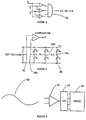
- FIGURE 4 there is shown an electrical schematic representation of the comparator used to generate the square wave signals shown in FIGURE 2b.
- This comparator bridge circuit is identified generally as reference numeral 40.
- Variable resistors R1 and R2 represent the halves 18 and 20 of the magneto resistive element 16 (FIGURE 1).
- variable resistor pairs R3, R4 and R5, R6 represent respective halves of the second and third magneto resistive elements in the preferred embodiment.
- Reference voltage 42 is common for all three sensor units.
- the reference voltage source 42 is a resistive divider in the preferred embodiment, but it should be understood that a Zener diode or battery can also be used to supply voltage.
- the comparator value A' is zero. Similarly, if R1 has a higher value than R2 the comparator output A' will be moved in a negative direction. When the electrical center tap voltage 38a is less than the reference voltage 42, the comparator output A' is zero. In all other cases the comparative value is proportionally positive. A +5 v power supply results in a signal output A', B' or C' of approximately 0.8 v peak to peak.
- FIGURE 5 there is shown a block diagram of a system that incorporates the high output high resolution transducer of the present invention.
- the electrical analog signal 50 is sinusoidal in the preferred embodiment. This is the signal that is output from the electrical center tap of one of the sensor units (FIGURE 1).
- the signal 50 is input to an amplifier 52 which, in turn, supplies an output signal to an analog to digital (A/D) converter 54.
- the A/D converter supplies a digital signal to a servo mechanism 56 used for positioning a movable member relative to a stationary member.
- FIGURE 5 results in high resolution with a minimum amount of circuitry and with no need for a sophisticated A/D apparatus.
- Such logic systems are well known in the art of digital or analog signal processing.
Landscapes
- Physics & Mathematics (AREA)
- General Physics & Mathematics (AREA)
- Measurement Of Length, Angles, Or The Like Using Electric Or Magnetic Means (AREA)
- Transmission And Conversion Of Sensor Element Output (AREA)
- Control Of Position Or Direction (AREA)
Description
- The present invention relates to a system for detecting relative position in accordance with the preamble of claim 1 (GB-A-1395 850).
- In the field of precision mechanical movements and machine positioning, it is becoming more important to determine relative position accurately and quickly. The relative position of two or more members or parts with respect to one another is especially critical in the fields of material handling, medicine and manufacturing. In the latter case, robotics is playing an ever increasing role.
- Manufacturers of highly sophisticated miniature equipment, for example, such as electronic components, printed circuit boards and the like, often require precise relative positioning to within some micrometers or less. Few systems are now capable of such high resolution, reliable measurements.
- Magneto resistive elements, whose electrical resistive characteristics or properties vary as a function of the magnetic flux density to which they are subjected, are well known. U.S. Patent No. 3,172,032, issued to Hunt, teaches a rudimentary magneto resistive element in which a servo mechanism is provided to operate in conjunction with a magnetic field generator to control the intensity of the magnetic field. The servo mechanism controls excitation current and ultimately the resistance of conductive paths.
- U.S. Patent No. 3,554,169, issued to Wahl et al., describes a fuel injection arrangement for internal combustion engines in which a magnetically sensitive resistor is subjected to a magnetic field that varies in intensity. By varying the resistance value of the magnetically sensitive resistor through variation of the magnetic field, an electronic timing network is varied as a function of a selected operating characteristic. The magnetically sensitive resistor provides a function in the aforementioned patent which is commonly referred to as coupling.
- U.S. Patent No. 3,846,697, issued to Cila et al., discloses a digital pickup for counting gear teeth. A pair of magneto resistors mounted on a permanent magnet sense the gear teeth. The magneto resistors are connected in a bridge circuit, the output of which triggers an IC switch to produce a digital output signal. The magneto resistors are directly mounted to one pole of a permanent magnet. This arrangement results in a relatively strong but coarse magnetic field, unsuitable for use with other magneto resistors due to the tendency for magnetic fields to interfere with one another. Moreover, the magneto resistors are not differential with respect to one another, resulting in coarse overall sensitivity.
- U.S. Patent No. 4,119,911, issued to Johnson, Jr., discloses a displacement transducer in which two toothed members have magnetic poles arranged in alternating sequence. The toothed members are arranged so that a magnetic pole on one of the members is spaced from a magnetic pole of opposite plurality on the other member. A magneto resistive element is held within the air gap between the magnetic poles to intercept magnetic flux lines. The magneto resistive element is in the form of a thin film material which is moved between the permanent magnets. The magneto resistive element has an electrical resistance which is dependent on the angular orientation and magnitude of the flux lines with respect to the element. A bridge circuit is connected to both ends of the magneto resistive element. By measuring the electrical resistance of the magneto resistive element, the angular orientation of the flux lines and the relative displacement of the toothed members can be obtained. The function of the apparatus hereinabove described is similar to that of a strain gage. The limit of resolution in this system is based on mechanical or physical limitations. That is, the dimension of the tooth or the length of the gap between magnetic poles is limited to approximately 200 µm at the present level of technology.
- U.S. Patent No. 3,949,345, issued to Makino et al., discloses a magnetoresistance element having two stripe groups aligned in different directions, requiring precise spacing between the stripe groups and relatively complex circuitry to process electrical information obtained therefrom.
- It is therefore the object of the present invention to provide a position sensing system of the aforementioned kind that allows to measure relative positions with high precision, needs relatively simple signal processing circuitry and is adaptable to various paths of relative motion.
- This object is achieved by the invention of
claim 1; embodiments are characterized in the dependent claims. - The present invention uses a magnetic field generator, e.g. a permanent magnet, whose lines of magnetic flux are concentrated onto one or several magneto resistive elements; each half of the latter is magnetically coupled to a reference scale with periodic protuberances. The magnetic flux is changed in the magneto resistive element according to its relative position to the reference scale, generating a difference signal that is electronically evaluated.
- The invention is particularly useful to measure relative positions in robotic equipments along linear or curved tracks; the focussing of the magnetic flux results in strong analog signals, that can be easily evaluated with great precision using simple analog and/or digital circuits.
- An embodiment of the invention is now described in detail with reference to the drawings, where:
- FIGURE 1
- is a cross sectional view of the sensor in accordance with the present invention and the transducer grid with which it cooperates;
- FIGURE 2a
- is a graph of transducer signal output as a function of relative position;
- FIGURE 2b
- is a square wave representation of the transducer signal output represented in FIGURE 2a and of a comparator output signal generated by logic gates in accordance with the present invention;
- FIGURE 3
- is a schematic representation of a 3-input AND-OR gate;
- FIGURE 4
- is a schematic representation of a comparator with magneto resistive elements and a reference voltage source; and
- FIGURE 5
- is a block diagram representation of a high resolution positioning system and servo mechanism in accordance with the present invention.
- Referring now to FIGURE 1 there is shown a
permanent magnet 10, shown with its north polarity oriented downwardly. Thispermanent magnet 10 can be fabricated of material that is dependent upon the size of the overall transducer. For relatively small dimensions, a permanent magnet made of rare earth material such as samarium cobalt or neodymium cobalt can be used. Larger transducer dimensions would allow the use of alnico magnets. - Connected to the
permanent magnet 10 is aflux concentrator 12 made of magnetically soft material. Theflux concentrator 12 can be attached to thepermanent magnet 10 or be in very close proximity thereto by use of common bonding or mechanical attachment techniques. It is important not to allow theflux concentrator 12 to develop a high remanent magnetic field. Theflux concentrator 12 is magnetically soft to allow the lines of flux in the permanent magnet to be concentrated through a vortex location in the concentrator shape, shown asreference numeral 14. Lines of flux from a relatively large area in thepermanent magnet 10 are thereby concentrated by theflux concentrator 12 at threevortex locations 14 in the preferred embodiment, labelled A, B and C in FIGURE 1. Theflux concentrator 12 can have any number ofvortex locations 14. It should be understood that the larger the number of vortex locations in a flux concentrator, the greater will be the resolution of the sensor. - At the end of each
vortex location 14 is a bar of magnetoresistive material 16, such as indium antimonide. This material has a specific electro mobility and therefore a specific resistance. Such material is described, for example, in U.S. Patent No. 3,934,160, issued to Von Borcke and in an article entitled "Magnetoresistor Differential Sensor FP 210" by the same author in the Siemens Electronic Components Bulletin VIII (1973) No. 2, pp. 53-56. The properties of the magnetoresistive element 16 allow an increase in magnetic field to result in an increase in resistivity in accordance with a parabolic function. In the preferred embodiment, the magnetic flux density in the region near the magnetoresistive element 16 is approximately 0.24 Tesla. - At a certain portion of the resistivity vs. magnetic field curve, the relationship between magnetic field and resistivity approaches linearity. There is no need to work only within that linear region, however, because the parabolic equation is well understood and can be used downstream in further signal processing to obtain a correction for this nonlinearity with a high degree of accuracy.
- The magneto
resistive element 16 has twohalves first half 18 of the magnetoresistive element 16 is aflux coupler 22. Theflux coupler 22 is irregularly shaped in a manner best suited to interface with a transducer grid, hereinafter described. Theflux coupler 22 is made of magnetically soft material. Similarly, connected to theother half 20 of the magnetoresistive element 16 is asecond flux coupler 24. The flux couplers 22 and 24 are terminated in twoflat feet vortex location 14, twohalves resistive element 16 and twoflux couplers - Oppositely disposed to the three transducer elements is a
transducer grid 30 which preferably consists of a magnetically soft material. Thetransducer grid 30 in the preferred embodiment has a plurality of uniformly dimensioned and uniformly spaced protuberances orteeth 32 which are flattened at their uppermost extremities and oriented to interact with theflux coupler feet transducer grid teeth 32, called grid spacing, is "x." - The
transducer grid teeth 32 may be linearly oriented, circularly oriented or may be disposed in any other geometric pattern as is most suitable for measuring the relative position of two specified machine elements or members with respect to one another. It should be noted that, with respect to thetransducer grid teeth 32, theflux couplers flux coupler foot 26 is directly oppositetransducer grid tooth 36 whereasflux coupler foot 28 is disposed precisely between twotransducer grid teeth halves resistive element 16 to modulate flux distribution. Onehalf 18 of the magnetoresistive element 16 distributes the magnetic lines of flux exactly opposite to the magnetic lines of flux distributed by theother half 20 of the magnetoresistive element 16. - The magneto
resistive element 16, divided intohalves electrical connection point 38a at which an electrical wire, not shown, can be attached. Thisconnection point 38a is referred to as an electrical center tap. An electrical signal generated atconnection point 38a can then be used for further signal processing as hereinafter described. - In the preferred embodiment of the present invention, three sensor units are disposed opposite the
transducer grid 30 for higher sensitivity and better resolution of position sensing information. Corresponding toelectrical center tap 38a on the first sensor unit are electrical center taps 38b and 38c on the second and third sensor units, respectively, to which electrical wires can also be attached. - The operation of the positioning sensors can best be described by referring also to FIGURE 2a. There are shown graphs which represent the electrical signal output from the three center taps 38a, 38b and 38c (FIGURE 1), respectively. The X axes of these graphs represent displacement or distance and the Y axis represents output voltage. The uppermost portion of the graph represents the output of
sensor unit 38a. The center portion of the graph represents the output ofsensor unit 38b. The lower portion of FIGURE 2a represents the output ofsensor unit 38c. - As the first sensor unit (FIGURE 1) is caused to move relative to the
transducer grid 30, the magnetic lines of flux generated by thepermanent magnet 10 are received by theflux concentrator 12 and are directed and concentrated to thevortex location 14. The flux density of the twohalves resistive element 16 is determined by the permeance along paths influx couplers flux couplers feet transducer grid teeth 32. - In the position shown in FIGURE 1, the magnetic field between the sensor unit and
transducer grid 30 is strongest betweenflux coupler foot 26 andtransducer grid tooth 36 as well as betweenfoot 28 and the tooth oppositely disposed. It should be noted that magnetic permeance is a function of both the air gap or distance betweenfoot 26 andtooth 36 and the surface area of the parallel surfaces (i.e., the projection of the surface of thefoot 26 on the tooth 36). At this instant, the magnetic field between the pair offlux coupler feet transducer grid tooth 36b is weakest. The electrical signal generated by the magnetoresistive element 16 at theelectrical center tap 38a is therefore relatively strongest at this time, due to the resistance differential of magneto resistive element halves 18 and 20 which is generated by bothflux couplers - The electrical signal generated by the second magneto
resistive element 16 at itselectrical center tap 38b is shown in the center graph, FIGURE 2a. It can be seen that the value of the electrical signal generated atelectrical center tap 38b is generally different than that generated atelectrical center tap 38a at any given instant. This is due to the fact that the first pair offlux couplers transducer grid teeth 32. - Similarly, the electrical signal generated by the third magneto resistive element at its
electrical center tap 38c is generally different than those generated at electrical center taps 38a and 38b at any given instant, as depicted by the lowermost portion of FIGURE 2a. - As the three sensor units move relative to the
transducer grid 30, the electrical signals generated by the electrical center taps 38a, 38b and 38c vary, but maintain their offset relationship with respect to one another. - The three signals can be processed (e.g., compared, added), resulting in the digital square wave graph depicted in FIGURE 2b. It should be noted that the uppermost three square wave signals represent the comparator output of the signals from electrical center taps 38a, 38b and 38c, respectively, when compared to a reference voltage, not shown in FIGURE 1, but represented by the X axes in FIGURE 2a. By convention, the signal A, when compared to the reference voltage, becomes A'. Similarly, signal B compared to the reference voltage becomes B' and signal C becomes C'.
- Referring to FIGURE 3, there is shown a three-input OR
gate 39, the inputs of which are generated by three two-way AND circuits that logically combine the output signals shown in FIGURE 2a. The sum of these three signals results in an output signal representing AB + BC + CA. The lowermost square wave graph of FIGURE 2b represents the output of the circuit shown in FIGURE 3. - Referring now also to FIGURE 4, there is shown an electrical schematic representation of the comparator used to generate the square wave signals shown in FIGURE 2b. This comparator bridge circuit is identified generally as
reference numeral 40. Variable resistors R₁ and R₂ represent thehalves Reference voltage 42 is common for all three sensor units. Thereference voltage source 42 is a resistive divider in the preferred embodiment, but it should be understood that a Zener diode or battery can also be used to supply voltage. - When the
reference voltage 42 and the electricalcenter tap output 38a are equal, the comparator value A' is zero. Similarly, if R₁ has a higher value than R₂ the comparator output A' will be moved in a negative direction. When the electricalcenter tap voltage 38a is less than thereference voltage 42, the comparator output A' is zero. In all other cases the comparative value is proportionally positive. A +5 v power supply results in a signal output A', B' or C' of approximately 0.8 v peak to peak. - Referring now to also FIGURE 5, there is shown a block diagram of a system that incorporates the high output high resolution transducer of the present invention. The
electrical analog signal 50 is sinusoidal in the preferred embodiment. This is the signal that is output from the electrical center tap of one of the sensor units (FIGURE 1). Thesignal 50 is input to anamplifier 52 which, in turn, supplies an output signal to an analog to digital (A/D)converter 54. The A/D converter supplies a digital signal to aservo mechanism 56 used for positioning a movable member relative to a stationary member. - The system shown in FIGURE 5 results in high resolution with a minimum amount of circuitry and with no need for a sophisticated A/D apparatus. To adapt the system for use with a plurality of sensor units, as is shown in the preferred embodiment (FIGURE 1), requires a logic system capable of summing the signals A, B and C before further signal processing thereof. Such logic systems are well known in the art of digital or analog signal processing.
Claims (10)
- System for detecting relative positions of machine elements and the like, using magneto resistive elements (14, 16) to sense the magnetic flux of a magnetic field generator (10), comprising:
at least one means (12) operatively connected to the magnetic field generator (10) for concentrating lines of magnetic flux produced thereby;
a magneto resistive element (16) operatively connected to each of the concentrating means;
a reference position scale (30) comprising a transducer grid with a plurality of periodic protuberances (36);
characterized in that:
two flux couplers (22, 24) operatively connected to each of the magneto resistive elements and disposed out of phase with one another with respect to the transducer grid for modulating flux distribution between the concentrating means and the transducer grid. - The system in accordance with claim 1 wherein the reference position scale (30) is adapted to move relative to the flux couplers (22, 24).
- The system in accordance with claim 1 or 2 wherein the two flux couplers associated with each concentrating means are disposed 180° out of phase with respect to one another.
- The system of one of the claims 1 to 3 wherein the pairs of flux couplers associated with each concentration means are disposed such that each pair has a different phase relationship with respect to the reference position scale.
- The system in accordance with one of the claims 1 to 4 wherein the transducer grid is linear.
- The system in accordance with one of the claims 1 to 4 wherein the transducer grid forms at least a portion of a curve.
- The system in accordance with one of the claims 1 to 6 wherein the reference position scale comprises magnetically soft material.
- The system of one of the claims 1 to 7 wherein each magneto resistive element is divided into two halves each of which is connected to one of the flux couplers and wherein an electrical tap (38) is provided at the intersection of the two halves to extract an analog position signal.
- The system of claim 8 wherein a bridge circuit (Fig. 4) is provided to compare the analog position signal of each electrical tap (38) to a reference voltage.
- The system of one of the claims 1 to 9 wherein either the magnetic field generator or the reference position scale is operatively connected to a position servo mechanism.
Applications Claiming Priority (2)
| Application Number | Priority Date | Filing Date | Title |
|---|---|---|---|
| US69597585A | 1985-01-28 | 1985-01-28 | |
| US695975 | 1985-01-28 |
Publications (3)
| Publication Number | Publication Date |
|---|---|
| EP0192812A2 EP0192812A2 (en) | 1986-09-03 |
| EP0192812A3 EP0192812A3 (en) | 1988-07-20 |
| EP0192812B1 true EP0192812B1 (en) | 1991-02-27 |
Family
ID=24795208
Family Applications (1)
| Application Number | Title | Priority Date | Filing Date |
|---|---|---|---|
| EP85109456A Expired EP0192812B1 (en) | 1985-01-28 | 1985-07-30 | Position sensing system |
Country Status (4)
| Country | Link |
|---|---|
| EP (1) | EP0192812B1 (en) |
| JP (1) | JPS61175504A (en) |
| CA (1) | CA1236543A (en) |
| DE (1) | DE3581928D1 (en) |
Families Citing this family (4)
| Publication number | Priority date | Publication date | Assignee | Title |
|---|---|---|---|---|
| DE69306914T2 (en) * | 1992-10-29 | 1997-05-07 | Rolls-Royce And Associates Ltd., Derby, Derbyshire | Improvement in signposts |
| GB2272060B (en) * | 1992-10-29 | 1996-05-22 | Rolls Royce & Ass | Improvements in and relating to position responsive apparatus |
| DE102006038162A1 (en) * | 2006-08-16 | 2008-02-21 | Siemens Ag | Electric motor with measuring system for position or movement |
| CN103808244A (en) * | 2014-02-28 | 2014-05-21 | 南京景曜智能科技有限公司 | Magnetic encoder for position measurement |
Family Cites Families (3)
| Publication number | Priority date | Publication date | Assignee | Title |
|---|---|---|---|---|
| DE2238525A1 (en) * | 1972-08-04 | 1974-02-14 | Siemens Ag | ARRANGEMENT FOR GENERATING ELECTRICAL SIGNALS BY MEANS OF MAGNETIC FIELD-DEPENDENT SEMICONDUCTOR COMPONENTS |
| US4024458A (en) * | 1976-06-15 | 1977-05-17 | General Motors Corporation | Electrical signal generating system |
| DE2739877A1 (en) * | 1977-09-05 | 1978-11-02 | Nestler Gmbh A | Digital position measuring system - has pick=up with two sensors near signal generator with teeth |
-
1985
- 1985-06-25 CA CA000485179A patent/CA1236543A/en not_active Expired
- 1985-07-30 DE DE8585109456T patent/DE3581928D1/en not_active Expired - Fee Related
- 1985-07-30 EP EP85109456A patent/EP0192812B1/en not_active Expired
- 1985-08-16 JP JP60179577A patent/JPS61175504A/en active Pending
Also Published As
| Publication number | Publication date |
|---|---|
| EP0192812A3 (en) | 1988-07-20 |
| EP0192812A2 (en) | 1986-09-03 |
| CA1236543A (en) | 1988-05-10 |
| JPS61175504A (en) | 1986-08-07 |
| DE3581928D1 (en) | 1991-04-04 |
Similar Documents
| Publication | Publication Date | Title |
|---|---|---|
| US4733177A (en) | High resolution high output magneto resistive transducer for determining static and dynamic position | |
| KR102482486B1 (en) | Magnetic field sensor for sensing a movement of a ferromagnetic target object | |
| US5341097A (en) | Asymmetrical magnetic position detector | |
| US4829248A (en) | Hall effect sensing apparatus and method | |
| JP6689839B2 (en) | Magnetic field sensor for detecting movement of target object | |
| JPS58190714A (en) | Magnetical measuring device for length or angle | |
| EP3469314B1 (en) | Magnetic field sensor for sensing a proximity and/or a location of an object | |
| JPH0379648B2 (en) | ||
| US5680042A (en) | Magnetoresistive sensor with reduced output signal jitter | |
| JP2846814B2 (en) | Position measuring device | |
| US6011390A (en) | Sensor chip with magnetoresistive wheatstone bridges for determining magnetic field directions | |
| GB2034053A (en) | Magneto resistive displacement sensors | |
| JP2819507B2 (en) | Magnetic measuring system | |
| GB2100443A (en) | Magnetic linear or rotary position transducer | |
| KR100978707B1 (en) | Magnetic rotary encoder and method for iteratively aligning magnet relative to magnetic sensors | |
| JP3487452B2 (en) | Magnetic detector | |
| EP0192812B1 (en) | Position sensing system | |
| WO2006020626A1 (en) | Precision non-contact digital switch | |
| US5072179A (en) | High resolution one and two dimensional position indicating apparatus with plural windings having a common connection and separately energized by signals of different phase | |
| JPS63212803A (en) | Measuring device for displacement | |
| JP3220278B2 (en) | Position detection device | |
| EP0608417A1 (en) | Method for sensing part where electromagnetic characteristics are changed, and device thereof | |
| JPS626537Y2 (en) | ||
| JP2556851B2 (en) | Magnetoresistive element | |
| JPH0718684B2 (en) | Position detector |
Legal Events
| Date | Code | Title | Description |
|---|---|---|---|
| PUAI | Public reference made under article 153(3) epc to a published international application that has entered the european phase |
Free format text: ORIGINAL CODE: 0009012 |
|
| AK | Designated contracting states |
Kind code of ref document: A2 Designated state(s): DE FR GB IT |
|
| 17P | Request for examination filed |
Effective date: 19861125 |
|
| PUAL | Search report despatched |
Free format text: ORIGINAL CODE: 0009013 |
|
| AK | Designated contracting states |
Kind code of ref document: A3 Designated state(s): DE FR GB IT |
|
| 17Q | First examination report despatched |
Effective date: 19900125 |
|
| GRAA | (expected) grant |
Free format text: ORIGINAL CODE: 0009210 |
|
| AK | Designated contracting states |
Kind code of ref document: B1 Designated state(s): DE FR GB IT |
|
| REF | Corresponds to: |
Ref document number: 3581928 Country of ref document: DE Date of ref document: 19910404 |
|
| ET | Fr: translation filed | ||
| ITF | It: translation for a ep patent filed | ||
| PLBE | No opposition filed within time limit |
Free format text: ORIGINAL CODE: 0009261 |
|
| STAA | Information on the status of an ep patent application or granted ep patent |
Free format text: STATUS: NO OPPOSITION FILED WITHIN TIME LIMIT |
|
| 26N | No opposition filed | ||
| PGFP | Annual fee paid to national office [announced via postgrant information from national office to epo] |
Ref country code: FR Payment date: 19920630 Year of fee payment: 8 |
|
| PGFP | Annual fee paid to national office [announced via postgrant information from national office to epo] |
Ref country code: DE Payment date: 19920729 Year of fee payment: 8 |
|
| PGFP | Annual fee paid to national office [announced via postgrant information from national office to epo] |
Ref country code: GB Payment date: 19930622 Year of fee payment: 9 |
|
| PG25 | Lapsed in a contracting state [announced via postgrant information from national office to epo] |
Ref country code: FR Effective date: 19940331 |
|
| PG25 | Lapsed in a contracting state [announced via postgrant information from national office to epo] |
Ref country code: DE Effective date: 19940401 |
|
| REG | Reference to a national code |
Ref country code: FR Ref legal event code: ST |
|
| PG25 | Lapsed in a contracting state [announced via postgrant information from national office to epo] |
Ref country code: GB Effective date: 19940730 |
|
| GBPC | Gb: european patent ceased through non-payment of renewal fee |
Effective date: 19940730 |