EP0608417A1 - Method for sensing part where electromagnetic characteristics are changed, and device thereof - Google Patents
Method for sensing part where electromagnetic characteristics are changed, and device thereof Download PDFInfo
- Publication number
- EP0608417A1 EP0608417A1 EP92907097A EP92907097A EP0608417A1 EP 0608417 A1 EP0608417 A1 EP 0608417A1 EP 92907097 A EP92907097 A EP 92907097A EP 92907097 A EP92907097 A EP 92907097A EP 0608417 A1 EP0608417 A1 EP 0608417A1
- Authority
- EP
- European Patent Office
- Prior art keywords
- electromagnetic
- changing portion
- characteristic changing
- bridge circuit
- electromagnetic characteristic
- Prior art date
- Legal status (The legal status is an assumption and is not a legal conclusion. Google has not performed a legal analysis and makes no representation as to the accuracy of the status listed.)
- Granted
Links
Images


Classifications
-
- G—PHYSICS
- G01—MEASURING; TESTING
- G01D—MEASURING NOT SPECIALLY ADAPTED FOR A SPECIFIC VARIABLE; ARRANGEMENTS FOR MEASURING TWO OR MORE VARIABLES NOT COVERED IN A SINGLE OTHER SUBCLASS; TARIFF METERING APPARATUS; MEASURING OR TESTING NOT OTHERWISE PROVIDED FOR
- G01D5/00—Mechanical means for transferring the output of a sensing member; Means for converting the output of a sensing member to another variable where the form or nature of the sensing member does not constrain the means for converting; Transducers not specially adapted for a specific variable
- G01D5/12—Mechanical means for transferring the output of a sensing member; Means for converting the output of a sensing member to another variable where the form or nature of the sensing member does not constrain the means for converting; Transducers not specially adapted for a specific variable using electric or magnetic means
- G01D5/14—Mechanical means for transferring the output of a sensing member; Means for converting the output of a sensing member to another variable where the form or nature of the sensing member does not constrain the means for converting; Transducers not specially adapted for a specific variable using electric or magnetic means influencing the magnitude of a current or voltage
- G01D5/142—Mechanical means for transferring the output of a sensing member; Means for converting the output of a sensing member to another variable where the form or nature of the sensing member does not constrain the means for converting; Transducers not specially adapted for a specific variable using electric or magnetic means influencing the magnitude of a current or voltage using Hall-effect devices
-
- G—PHYSICS
- G01—MEASURING; TESTING
- G01B—MEASURING LENGTH, THICKNESS OR SIMILAR LINEAR DIMENSIONS; MEASURING ANGLES; MEASURING AREAS; MEASURING IRREGULARITIES OF SURFACES OR CONTOURS
- G01B7/00—Measuring arrangements characterised by the use of electric or magnetic techniques
- G01B7/003—Measuring arrangements characterised by the use of electric or magnetic techniques for measuring position, not involving coordinate determination
-
- G—PHYSICS
- G01—MEASURING; TESTING
- G01D—MEASURING NOT SPECIALLY ADAPTED FOR A SPECIFIC VARIABLE; ARRANGEMENTS FOR MEASURING TWO OR MORE VARIABLES NOT COVERED IN A SINGLE OTHER SUBCLASS; TARIFF METERING APPARATUS; MEASURING OR TESTING NOT OTHERWISE PROVIDED FOR
- G01D5/00—Mechanical means for transferring the output of a sensing member; Means for converting the output of a sensing member to another variable where the form or nature of the sensing member does not constrain the means for converting; Transducers not specially adapted for a specific variable
- G01D5/12—Mechanical means for transferring the output of a sensing member; Means for converting the output of a sensing member to another variable where the form or nature of the sensing member does not constrain the means for converting; Transducers not specially adapted for a specific variable using electric or magnetic means
- G01D5/14—Mechanical means for transferring the output of a sensing member; Means for converting the output of a sensing member to another variable where the form or nature of the sensing member does not constrain the means for converting; Transducers not specially adapted for a specific variable using electric or magnetic means influencing the magnitude of a current or voltage
- G01D5/142—Mechanical means for transferring the output of a sensing member; Means for converting the output of a sensing member to another variable where the form or nature of the sensing member does not constrain the means for converting; Transducers not specially adapted for a specific variable using electric or magnetic means influencing the magnitude of a current or voltage using Hall-effect devices
- G01D5/147—Mechanical means for transferring the output of a sensing member; Means for converting the output of a sensing member to another variable where the form or nature of the sensing member does not constrain the means for converting; Transducers not specially adapted for a specific variable using electric or magnetic means influencing the magnitude of a current or voltage using Hall-effect devices influenced by the movement of a third element, the position of Hall device and the source of magnetic field being fixed in respect to each other
-
- G—PHYSICS
- G01—MEASURING; TESTING
- G01D—MEASURING NOT SPECIALLY ADAPTED FOR A SPECIFIC VARIABLE; ARRANGEMENTS FOR MEASURING TWO OR MORE VARIABLES NOT COVERED IN A SINGLE OTHER SUBCLASS; TARIFF METERING APPARATUS; MEASURING OR TESTING NOT OTHERWISE PROVIDED FOR
- G01D5/00—Mechanical means for transferring the output of a sensing member; Means for converting the output of a sensing member to another variable where the form or nature of the sensing member does not constrain the means for converting; Transducers not specially adapted for a specific variable
- G01D5/12—Mechanical means for transferring the output of a sensing member; Means for converting the output of a sensing member to another variable where the form or nature of the sensing member does not constrain the means for converting; Transducers not specially adapted for a specific variable using electric or magnetic means
- G01D5/244—Mechanical means for transferring the output of a sensing member; Means for converting the output of a sensing member to another variable where the form or nature of the sensing member does not constrain the means for converting; Transducers not specially adapted for a specific variable using electric or magnetic means influencing characteristics of pulses or pulse trains; generating pulses or pulse trains
- G01D5/245—Mechanical means for transferring the output of a sensing member; Means for converting the output of a sensing member to another variable where the form or nature of the sensing member does not constrain the means for converting; Transducers not specially adapted for a specific variable using electric or magnetic means influencing characteristics of pulses or pulse trains; generating pulses or pulse trains using a variable number of pulses in a train
- G01D5/2451—Incremental encoders
-
- G—PHYSICS
- G01—MEASURING; TESTING
- G01P—MEASURING LINEAR OR ANGULAR SPEED, ACCELERATION, DECELERATION, OR SHOCK; INDICATING PRESENCE, ABSENCE, OR DIRECTION, OF MOVEMENT
- G01P3/00—Measuring linear or angular speed; Measuring differences of linear or angular speeds
- G01P3/42—Devices characterised by the use of electric or magnetic means
- G01P3/44—Devices characterised by the use of electric or magnetic means for measuring angular speed
- G01P3/48—Devices characterised by the use of electric or magnetic means for measuring angular speed by measuring frequency of generated current or voltage
- G01P3/481—Devices characterised by the use of electric or magnetic means for measuring angular speed by measuring frequency of generated current or voltage of pulse signals
- G01P3/488—Devices characterised by the use of electric or magnetic means for measuring angular speed by measuring frequency of generated current or voltage of pulse signals delivered by variable reluctance detectors
Definitions
- This invention relates to a method and a device for detecting an electromagnetic characteristic changing portion formed on a member to be detected such as a position detecting device of a hydraulic cylinder, a linear scale and a rotary encoder.
- an electromagnetic characteristic changing portion consisting of concave and convex grooves is formed on a scale and the magnetic field is applied to the electromagnetic characteristic changing portion to detect fluctuation of magnetic flux caused by the electromagnetic characteristic changing portion by using an electromagnetic sensing element such as a ferromagnetic thin-film magneto-resistive element.
- an electromagnetic sensing element such as a ferromagnetic thin-film magneto-resistive element.
- a bridge circuit is made up of four magneto-resistive elements.
- Fig. 4 (A) four magneto-resistive elements 10a through 10d are arranged along a graduation 14 consisting of concave and convex grooves formed on a scale 12. Then, when the magneto-resistive element 10a and the next magneto-resistive element 10c but one are simultaneously located at a position corresponding to a convex region 16 of the scale 12, the remaining two magneto-resistive elements 10b and 10d are located at a position corresponding to a concave region 18.
- the magneto-resistive elements 10a through 10d constitute, as shown in Fig. 4 (B), a bridge circuit 20 that serves as a detection circuit. More particularly, the cross-hatched magneto-resistive elements 10a and 10c that arrive simultaneously to the position corresponding to the convex region 16 compose opposing two sides of the bridge circuit 20. The magneto-resistive elements 10b and 10d that arrive to the position corresponding to the concave region 18 compose the other opposing two sides of the bridge circuit 20.
- an output E of the bridge circuit 20 can be represented by: E ⁇ Rb ⁇ Rd - Ra ⁇ Rc (1).
- the scale 12 is formed by the concave and convex grooves consisting of the convex regions 16 and the concave regions 18. Accordingly, as shown in Fig. 5, the magnetic field (magnetic flux ⁇ ) applied by a magnet 22 is fluctuated and deviated at the edged portions of the convex regions 16 of the scale 12. As a result, when the output of the bridge circuit 20 has a repetitious waveform as in the case of a position sensor, it is possible to carry out successfully a comparator processing for digitizing repeatedly the output of the bridge circuit 20.
- the electromagnetic characteristic changing portion(s) is/are formed singly or at spaces relative to the member to be detected to allow generation of so-called one-pulsed waveform (1 bit) as in the case of, for example, detecting an original point or the like of the scale, small waves as a noise are frequently generated beside the fundamental wave due to the fluctuation of the magnetic field caused around the electromagnetic characteristic changing portions, which makes the comparator processing difficult.
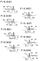
- each of the magneto-resistive elements 10a through 10d constituting the bridge circuit 20 is passed over the electromagnetic characteristic changing portion formed of the convex portion 16 of the scale 12 as shown in Figs. 6(A) through 6(H).
- the resistance values thereof are not changed when the magnetic field is applied to the element in a perpendicular direction while the resistance values thereof are reduced when the magnetic field is fluctuated at the electromagnetic characteristic changing portion of the convex region 16 to apply a transversal component to the element.
- the electromagnetic characteristic changing portion is formed by means of polarization and magneto-sensitive directions of two pairs of ferromagnetic magneto-resistive elements connected in series are orthogonally crossed each other, thereby a difference between the outputs of the two is detected.
- the output waveform becomes larger in width and in area, which causes degraded accuracy of detection.
- the present invention is made to overcome the above mentioned problems inherent to conventional arts and is directed to provide a method and a device for detecting an electromagnetic characteristic changing portion that are capable of detecting a single electromagnetic characteristic changing portion with high accuracy as well as of obtaining an output waveform having narrow peak width.
- the output E of the bridge circuit is proportional to, as apparent from Equation (1), the difference of products of the electrical resistance values on the opposing two sides.
- the received wisdom is that the opposing two sides of the bridge circuit formed of the elements located at the positions corresponding both to the convex and concave regions make the first and the second terms of the right-hand side of Equation (1) be approximately equal to obtain no output E of the bridge circuit.
- the distribution on the left side of the center of the convex region differs from, as shown in Figs. 6(A) through 6(H), that on the right side thereof due to a lateral bias.
- the fluctuation of the magnetic flux is not symmetrically caused at the convex region, which may be a cause of production of the above mentioned plural output signals.
- the present inventors have found that an output signal is available even when the opposing two sides of the bridge circuit are formed of the elements located at the positions corresponding both to the convex and concave regions, i.e., when they are so connected that the detected signals are cancelled.
- the present invention is made on the basis of these findings, and a method for detecting an electromagnetic characteristic changing portion according to the present invention connects, in the method for detecting the electromagnetic characteristic changing portion comprising the steps of aligning in a row in a direction of a relative movement a member to be detected having the electromagnetic characteristic changing portion and four electromagnetic sensing elements relatively move; aligning them in such a manner that when two out of four are simultaneously located at a position corresponding to said electromagnetic characteristic changing portion as a result of relative movement the remaining two are located at a position not corresponding to the electromagnetic characteristic changing portion; and connecting these four electromagnetic sensing elements to four sides of a bridge circuit, respectively, thereby detecting the electromagnetic characteristic changing portion, two opposing sides of said bridge circuit to one electromagnetic sensing element located at the position corresponding to said electromagnetic characteristic changing portion and one electromagnetic sensing element located at the position not corresponding to said electromagnetic characteristic changing portion.
- a device for detecting an electromagnetic characteristic changing portion connects, in the device for detecting the electromagnetic characteristic changing portion comprising four electromagnetic sensing elements that relatively move to a member to be detected having the electromagnetic characteristic changing portion and that are aligned in a row in a direction of the relative movement; and a bridge circuit of which four sides being formed of the respective four electromagnetic sensing elements, outer two of said four electromagnetic sensing elements aligned in a row to the opposing two sides, respectively, of said bridge circuit and connects inner two to the remaining opposing two sides, respectively, of the bridge circuit.
- each element is formed in ⁇ /4 or slightly smaller than ⁇ /4 while a pitch between the magneto-resistive elements is defined in ⁇ /4 or slightly larger than ⁇ /4.
- Fig. 1(A) is a perspective view showing each magneto-resistive element aligned on an electromagnetic characteristic changing portion according to an embodiment of the present invention
- Fig. 1(B) is a view of a bridge circuit formed of these magneto-resistive elements
- Fig. 2 is a typical view showing an output waveform of the bridge circuit according to the present embodiment
- Fig. 3 is a diagram showing exemplified output waveforms of the bridge circuit according to the present embodiment.
- Fig. 4(A) is a perspective view showing each magneto-resistive element aligned on a conventional electromagnetic characteristic changing portion
- Fig. 4(B) is a view of a bridge circuit formed of these magneto-resistive elements
- Fig. 5 is a perspective view showing how the magnetic field is applied to the electromagnetic characteristic changing portion
- Figs. 6(A) through 6(H) are views for use in describing a method for detecting the electromagnetic characteristic changing portion
- Fig. 7 is a diagram showing exemplified output waveforms of the conventional bridge circuit.
- Fig. 1 is a view for use in describing a method and a device for detecting the electromagnetic characteristic changing portion according to an embodiment of the present invention, in which Fig. 1(A) shows an alignment condition of each electromagnetic sensing element while Fig. 1(B) shows a view of a bridge circuit formed of these electromagnetic sensing elements.
- each of the magneto-resistive elements 10A through 10D that serve as the electromagnetic sensing elements are arranged in a row along the graduation 14 of the scale 12 or a member to be detected.
- Each of the magneto-resistive elements 10A through 10D is contained in a magnetic shield case or the like not being shown and is so held as to be movable relative to the scale 12.
- the width of each of the magneto-resistive elements 10A through 10D is defined, if the width of the convex region 16 or the electromagnetic characteristic changing portion of the scale 12 is equal to ⁇ /2, as half it or ⁇ /4 or slightly smaller than the latter.
- two elements 10A and 10B out of the magneto-resistive elements 10A through 10D are simultaneously located at the position corresponding to the convex region 16, the other two elements 10C and 10D are located at the position corresponding to the concave region 18.
- the magneto-resistive elements 10A through 10D constitute, as shown in Fig. 1(B), a bridge circuit 30 that serves as a detection circuit.
- the bridge circuit 30 differs from the bridge circuit 20 described in conjunction with the background art in that the cross-hatched two magneto-resistive elements 10A and 10D located at the position corresponding to the convex region 16 and the concave region 18, respectively, out of four magneto-resistive elements 10A through 10D aligned in a row form two opposing sides, respectively, of the bridge circuit 30.
- the first term of the right-hand side of Equation (2) is a product of the resistance value R B of the magneto-resistive element 10B located at the position corresponding to the convex region 16 and the resistance value R C of the magneto-resistive element 10C located at the position corresponding to the concave region 18, and the second term is represented as a product of the resistance value R A of the magneto-resistive element 10A located at the position corresponding to the convex region 16 and the resistance value R D of the magneto-resistive element 10D located at the position corresponding to the concave region 18.
- the output E is proportional to the difference between the first and the second terms.
- a typical representation of the output waveform of the bridge circuit 30 is as shown in Fig. 2, where one large peaks is formed on the positive and the negative sides relative to the zero point of the reference voltage.
- the reference numerals A through H in Fig. 2 correspond to the cases of these conditions shown in Figs. 6(A) through 6(H), respectively.
- Fig. 3 is a representation of the output waveform of the bridge circuit 30 when the convex region 16 of the scale 12 is formed in 1 mm, the width of each of the magneto-resistive elements 10A through 10D is formed in slightly smaller than 0.5 mm, and the pitch between the elements is formed in 0.5 mm.
- obtained is the waveform having one large peak one the positive side or on the negative side, so that it is possible to readily and positively detect the single electromagnetic characteristic changing portion formed for one bit such as an original point.
- the narrower width of the waveform results in an improved accuracy of detection.
- the bridge circuit 30 is made up of four magneto-resistive elements 10A through 10D, which allows cancellation of an influence due to a change of the temperature.
- the accuracy of detection is improved even when the electromagnetic characteristic changing portion is varied cyclically and continuously as in the case of the graduation of the scale. Consequently, it becomes possible to reduce an influence of a noise or the like to reduce detection errors.
- the peak can be increased by means of adjusting the magnetic field biased laterally. In particular, the bias in 45° direction enables to increasing the peak length.
- the electromagnetic sensing elements are ferromagnetic magneto-resistive elements 10A through 10D
- the electromagnetic sensing elements are not limited to the ferromagnetic magneto-resistive elements and may be semiconductor magneto-resistive elements or Hall elements, or may be coils or the like.
- the electromagnetic characteristic changing portion is formed of the convex regions 16
- the electromagnetic characteristic changing portion may be formed by means of polarization or the like.
- the above mentioned embodiment has thus been described in conjunction with the case where the scale 12 is formed in straight line, it may apparently be applicable to a rotary encoder or the like.
- the opposing two sides of the bridge circuit are formed of the electromagnetic sensing element located at the position corresponding to the electromagnetic characteristic changing portion and the electromagnetic sensing element located at the position not corresponding to the electromagnetic characteristic changing portion, respectively, out of the four electromagnetic sensing elements aligned in a row.
- the present invention is useful as a method and a device for detecting, with high accuracy, an electromagnetic characteristic changing portion formed on a member to be detected such as a position detecting device of a hydraulic cylinder, a linear scale and a rotary encoder.
Abstract

Description
- This invention relates to a method and a device for detecting an electromagnetic characteristic changing portion formed on a member to be detected such as a position detecting device of a hydraulic cylinder, a linear scale and a rotary encoder.
- Conventionally, in a position sensor or the like, an electromagnetic characteristic changing portion consisting of concave and convex grooves is formed on a scale and the magnetic field is applied to the electromagnetic characteristic changing portion to detect fluctuation of magnetic flux caused by the electromagnetic characteristic changing portion by using an electromagnetic sensing element such as a ferromagnetic thin-film magneto-resistive element. To detect the fluctuation of magnetic flux with a high sensibility, a bridge circuit is made up of four magneto-resistive elements.
- More particularly, as shown in Fig. 4 (A), four magneto-
resistive elements 10a through 10d are arranged along agraduation 14 consisting of concave and convex grooves formed on ascale 12. Then, when the magneto-resistive element 10a and the next magneto-resistive element 10c but one are simultaneously located at a position corresponding to aconvex region 16 of thescale 12, the remaining two magneto-resistive elements concave region 18. - Furthermore, the magneto-
resistive elements 10a through 10d constitute, as shown in Fig. 4 (B), abridge circuit 20 that serves as a detection circuit. More particularly, the cross-hatched magneto-resistive elements region 16 compose opposing two sides of thebridge circuit 20. The magneto-resistive elements concave region 18 compose the other opposing two sides of thebridge circuit 20. In this event, if Ra through Rd denote electrical resistance of the magneto-resistive elements 10a through 10d, respectively, then an output E of thebridge circuit 20 can be represented by:

- In the
bridge circuit 20 made up of in the manner described above, thescale 12 is formed by the concave and convex grooves consisting of theconvex regions 16 and theconcave regions 18. Accordingly, as shown in Fig. 5, the magnetic field (magnetic flux φ) applied by amagnet 22 is fluctuated and deviated at the edged portions of theconvex regions 16 of thescale 12. As a result, when the output of thebridge circuit 20 has a repetitious waveform as in the case of a position sensor, it is possible to carry out successfully a comparator processing for digitizing repeatedly the output of thebridge circuit 20. - However, when the electromagnetic characteristic changing portion(s) is/are formed singly or at spaces relative to the member to be detected to allow generation of so-called one-pulsed waveform (1 bit) as in the case of, for example, detecting an original point or the like of the scale, small waves as a noise are frequently generated beside the fundamental wave due to the fluctuation of the magnetic field caused around the electromagnetic characteristic changing portions, which makes the comparator processing difficult.
- Now, each of the magneto-
resistive elements 10a through 10d constituting thebridge circuit 20 is passed over the electromagnetic characteristic changing portion formed of theconvex portion 16 of thescale 12 as shown in Figs. 6(A) through 6(H). By the way, for the electrical resistance Ra through Rd, the resistance values thereof are not changed when the magnetic field is applied to the element in a perpendicular direction while the resistance values thereof are reduced when the magnetic field is fluctuated at the electromagnetic characteristic changing portion of theconvex region 16 to apply a transversal component to the element. Accordingly, the output E obtained in Equation 1 varies as follows:
For the condition shown in Fig. 6(A),

For the condition shown in Fig. 6(B),

For the condition shown in Fig. 6(C),

For the condition shown in Fig. 6(D),

For the condition shown in Fig. 6(E),

For the condition shown in Fig. 6(F),

For the condition shown in Fig. 6(G),

For the condition shown in Fig. 6(H),

- As apparent from the above, a plurality of output signals are produced on the positive side or on the negative side of the reference voltage (zero point). Consequently, in a conventional method for detecting the electromagnetic characteristic changing portion, detection of the one-pulsed waveform results in detection of two output waveforms having approximately equal peaks on the positive side or on the negative side, which may be a cause of detection errors.
- On the other hand, as disclosed in, for example, Japanese Patent Publication No. 56-1567, there are some cases where the electromagnetic characteristic changing portion is formed by means of polarization and magneto-sensitive directions of two pairs of ferromagnetic magneto-resistive elements connected in series are orthogonally crossed each other, thereby a difference between the outputs of the two is detected. In such a case, however, the output waveform becomes larger in width and in area, which causes degraded accuracy of detection.
- The present invention is made to overcome the above mentioned problems inherent to conventional arts and is directed to provide a method and a device for detecting an electromagnetic characteristic changing portion that are capable of detecting a single electromagnetic characteristic changing portion with high accuracy as well as of obtaining an output waveform having narrow peak width.
- The output E of the bridge circuit is proportional to, as apparent from Equation (1), the difference of products of the electrical resistance values on the opposing two sides. Up to the present, the received wisdom is that the opposing two sides of the bridge circuit formed of the elements located at the positions corresponding both to the convex and concave regions make the first and the second terms of the right-hand side of Equation (1) be approximately equal to obtain no output E of the bridge circuit.
- However, according to the experiments conducted by the present inventors, concerning the distribution of the magnetic flux at the convex region for example, the distribution on the left side of the center of the convex region differs from, as shown in Figs. 6(A) through 6(H), that on the right side thereof due to a lateral bias. In addition, the fluctuation of the magnetic flux is not symmetrically caused at the convex region, which may be a cause of production of the above mentioned plural output signals. Further, the present inventors have found that an output signal is available even when the opposing two sides of the bridge circuit are formed of the elements located at the positions corresponding both to the convex and concave regions, i.e., when they are so connected that the detected signals are cancelled.
- The present invention is made on the basis of these findings, and a method for detecting an electromagnetic characteristic changing portion according to the present invention connects, in the method for detecting the electromagnetic characteristic changing portion comprising the steps of aligning in a row in a direction of a relative movement a member to be detected having the electromagnetic characteristic changing portion and four electromagnetic sensing elements relatively move; aligning them in such a manner that when two out of four are simultaneously located at a position corresponding to said electromagnetic characteristic changing portion as a result of relative movement the remaining two are located at a position not corresponding to the electromagnetic characteristic changing portion; and connecting these four electromagnetic sensing elements to four sides of a bridge circuit, respectively, thereby detecting the electromagnetic characteristic changing portion, two opposing sides of said bridge circuit to one electromagnetic sensing element located at the position corresponding to said electromagnetic characteristic changing portion and one electromagnetic sensing element located at the position not corresponding to said electromagnetic characteristic changing portion.
- In addition, a device for detecting an electromagnetic characteristic changing portion according to the present invention connects, in the device for detecting the electromagnetic characteristic changing portion comprising four electromagnetic sensing elements that relatively move to a member to be detected having the electromagnetic characteristic changing portion and that are aligned in a row in a direction of the relative movement; and a bridge circuit of which four sides being formed of the respective four electromagnetic sensing elements, outer two of said four electromagnetic sensing elements aligned in a row to the opposing two sides, respectively, of said bridge circuit and connects inner two to the remaining opposing two sides, respectively, of the bridge circuit.
- It is preferable that, if the width of the electromagnetic characteristic changing portion is equal to λ/2, each element is formed in λ/4 or slightly smaller than λ/4 while a pitch between the magneto-resistive elements is defined in λ/4 or slightly larger than λ/4.
- According to the above mentioned structure, it is possible to remove an influence of a plurality of output waveforms due to the fluctuation of the magnetic field generated at an edge of the electromagnetic characteristic changing portion to obtain a single output waveform corresponding to the electromagnetic characteristic changing portion. In addition, it is possible to obtain an output waveform having a narrow peak width, allowing easy and highly accurate detection of the single electromagnetic characteristic changing portion.
- Fig. 1(A) is a perspective view showing each magneto-resistive element aligned on an electromagnetic characteristic changing portion according to an embodiment of the present invention; Fig. 1(B) is a view of a bridge circuit formed of these magneto-resistive elements; Fig. 2 is a typical view showing an output waveform of the bridge circuit according to the present embodiment; and Fig. 3 is a diagram showing exemplified output waveforms of the bridge circuit according to the present embodiment.
- Fig. 4(A) is a perspective view showing each magneto-resistive element aligned on a conventional electromagnetic characteristic changing portion; Fig. 4(B) is a view of a bridge circuit formed of these magneto-resistive elements; Fig. 5 is a perspective view showing how the magnetic field is applied to the electromagnetic characteristic changing portion; Figs. 6(A) through 6(H) are views for use in describing a method for detecting the electromagnetic characteristic changing portion; and Fig. 7 is a diagram showing exemplified output waveforms of the conventional bridge circuit.
- A preferred embodiment of a method and a device for detecting an electromagnetic characteristic changing portion according to the present invention is described with reference to the attached drawing. Corresponding parts are shown in like reference numerals to those described in conjunction with the background art and description thereof will be omitted.
- Fig. 1 is a view for use in describing a method and a device for detecting the electromagnetic characteristic changing portion according to an embodiment of the present invention, in which Fig. 1(A) shows an alignment condition of each electromagnetic sensing element while Fig. 1(B) shows a view of a bridge circuit formed of these electromagnetic sensing elements.
- Four magneto-resistive elements 10A through 10D that serve as the electromagnetic sensing elements are arranged in a row along the
graduation 14 of thescale 12 or a member to be detected. Each of the magneto-resistive elements 10A through 10D is contained in a magnetic shield case or the like not being shown and is so held as to be movable relative to thescale 12. In addition, the width of each of the magneto-resistive elements 10A through 10D is defined, if the width of theconvex region 16 or the electromagnetic characteristic changing portion of thescale 12 is equal to λ/2, as half it or λ/4 or slightly smaller than the latter. Accordingly, two elements 10A and 10B out of the magneto-resistive elements 10A through 10D are simultaneously located at the position corresponding to theconvex region 16, the other two elements 10C and 10D are located at the position corresponding to theconcave region 18. - In addition, the magneto-resistive elements 10A through 10D constitute, as shown in Fig. 1(B), a bridge circuit 30 that serves as a detection circuit. The bridge circuit 30 differs from the
bridge circuit 20 described in conjunction with the background art in that the cross-hatched two magneto-resistive elements 10A and 10D located at the position corresponding to theconvex region 16 and theconcave region 18, respectively, out of four magneto-resistive elements 10A through 10D aligned in a row form two opposing sides, respectively, of the bridge circuit 30. In addition, the remaining two magneto-resistive elements 10B and 10C located at the position corresponding to theconvex region 16 and theconcave region 18, respectively, form the other two opposing sides, respectively, of the bridge circuit 30. Consequently, if RA through RD denote electrical resistance of the magneto-resistive elements 10A through 10D, respectively, then an output E of the bridge circuit 30 can be represented by:

- As apparent from the above, the first term of the right-hand side of Equation (2) is a product of the resistance value RB of the magneto-resistive element 10B located at the position corresponding to the
convex region 16 and the resistance value RC of the magneto-resistive element 10C located at the position corresponding to theconcave region 18, and the second term is represented as a product of the resistance value RA of the magneto-resistive element 10A located at the position corresponding to theconvex region 16 and the resistance value RD of the magneto-resistive element 10D located at the position corresponding to theconcave region 18. The output E is proportional to the difference between the first and the second terms. - In this event, when each of the magneto-resistive elements 10A through 10D constituting the bridge circuit 30 passes over the
convex region 16 acting as the electromagnetic characteristic changing portion as shown in Figs. 6(A) through 6(H), the output E varies as follows:
For the condition shown in Fig. 6(A),

For the condition shown in Fig. 6(B),

For the condition shown in Fig. 6(C),

For the condition shown in Fig. 6(D),

For the condition shown in Fig. 6(E),

For the condition shown in Fig. 6(F),

For the condition shown in Fig. 6(G),

For the condition shown in Fig. 6(H),

- More particularly, a typical representation of the output waveform of the bridge circuit 30 is as shown in Fig. 2, where one large peaks is formed on the positive and the negative sides relative to the zero point of the reference voltage. The reference numerals A through H in Fig. 2 correspond to the cases of these conditions shown in Figs. 6(A) through 6(H), respectively.
- Fig. 3 is a representation of the output waveform of the bridge circuit 30 when the
convex region 16 of thescale 12 is formed in 1 mm, the width of each of the magneto-resistive elements 10A through 10D is formed in slightly smaller than 0.5 mm, and the pitch between the elements is formed in 0.5 mm. As shown in the figure, obtained is the waveform having one large peak one the positive side or on the negative side, so that it is possible to readily and positively detect the single electromagnetic characteristic changing portion formed for one bit such as an original point. Besides, the narrower width of the waveform results in an improved accuracy of detection. - In addition, the bridge circuit 30 is made up of four magneto-resistive elements 10A through 10D, which allows cancellation of an influence due to a change of the temperature. Of course, the accuracy of detection is improved even when the electromagnetic characteristic changing portion is varied cyclically and continuously as in the case of the graduation of the scale. Consequently, it becomes possible to reduce an influence of a noise or the like to reduce detection errors. Further, the peak can be increased by means of adjusting the magnetic field biased laterally. In particular, the bias in 45° direction enables to increasing the peak length.
- While the above mentioned embodiment has thus been described in conjunction with the case where the electromagnetic sensing elements are ferromagnetic magneto-resistive elements 10A through 10D, the electromagnetic sensing elements are not limited to the ferromagnetic magneto-resistive elements and may be semiconductor magneto-resistive elements or Hall elements, or may be coils or the like. In addition, while the above mentioned embodiment has thus been described in conjunction with the case where the electromagnetic characteristic changing portion is formed of the
convex regions 16, the electromagnetic characteristic changing portion may be formed by means of polarization or the like. Furthermore, while the above mentioned embodiment has thus been described in conjunction with the case where thescale 12 is formed in straight line, it may apparently be applicable to a rotary encoder or the like. - As described above, according to the present invention, the opposing two sides of the bridge circuit are formed of the electromagnetic sensing element located at the position corresponding to the electromagnetic characteristic changing portion and the electromagnetic sensing element located at the position not corresponding to the electromagnetic characteristic changing portion, respectively, out of the four electromagnetic sensing elements aligned in a row. As a result, it is provided a 1-force waveform having one peak that is narrow in width on one side relative to the reference voltage and it is possible to detect a single electromagnetic characteristic changing portion such as an original point with high accuracy.
- The present invention is useful as a method and a device for detecting, with high accuracy, an electromagnetic characteristic changing portion formed on a member to be detected such as a position detecting device of a hydraulic cylinder, a linear scale and a rotary encoder.
Claims (2)
- A method for detecting an electromagnetic characteristic changing portion comprising the steps of aligning in a row in a direction of a relative movement a member to be detected having the electromagnetic characteristic changing portion and four electromagnetic sensing elements relatively move; aligning them in such a manner that when two out of four are simultaneously located at a position corresponding to said electromagnetic characteristic changing portion as a result of relative movement the remaining two are located at a position not corresponding to the electromagnetic characteristic changing portion; and connecting these four electromagnetic sensing elements to four sides of a bridge circuit, respectively, thereby detecting the electromagnetic characteristic changing portion, wherein the method for detecting the electromagnetic characteristic changing portion is characterized in that:
two opposing sides of said bridge circuit are connected to one electromagnetic sensing element located at the position corresponding to said electromagnetic characteristic changing portion and one electromagnetic sensing element located at the position not corresponding to said electromagnetic characteristic changing portion. - A device for detecting an electromagnetic characteristic changing portion comprising four electromagnetic sensing elements that relatively move to a member to be detected having the electromagnetic characteristic changing portion and that are aligned in a row in a direction of the relative movement; and a bridge circuit of which four sides being formed of the respective four electromagnetic sensing elements, wherein the device for detecting the electromagnetic characteristic changing portion is characterized in that:
outer two of said four electromagnetic sensing elements aligned in a row are connected to the opposing two sides, respectively, of said bridge circuit and inner two are connected to the remaining opposing two sides, respectively, of the bridge circuit.
Applications Claiming Priority (3)
| Application Number | Priority Date | Filing Date | Title |
|---|---|---|---|
| JP3091353A JP2978582B2 (en) | 1991-03-29 | 1991-03-29 | Method and apparatus for detecting electromagnetic characteristic change section |
| JP91353/91 | 1991-03-29 | ||
| PCT/JP1992/000352 WO1992017749A1 (en) | 1991-03-29 | 1992-03-24 | Method for sensing part where electromagnetic characteristics are changed, and device thereof |
Publications (3)
| Publication Number | Publication Date |
|---|---|
| EP0608417A4 EP0608417A4 (en) | 1994-02-22 |
| EP0608417A1 true EP0608417A1 (en) | 1994-08-03 |
| EP0608417B1 EP0608417B1 (en) | 1998-05-13 |
Family
ID=14024035
Family Applications (1)
| Application Number | Title | Priority Date | Filing Date |
|---|---|---|---|
| EP92907097A Expired - Lifetime EP0608417B1 (en) | 1991-03-29 | 1992-03-24 | Method for sensing part where electromagnetic characteristics are changed, and device thereof |
Country Status (6)
| Country | Link |
|---|---|
| US (1) | US5436560A (en) |
| EP (1) | EP0608417B1 (en) |
| JP (1) | JP2978582B2 (en) |
| AU (1) | AU1445892A (en) |
| DE (1) | DE69225491T2 (en) |
| WO (1) | WO1992017749A1 (en) |
Cited By (1)
| Publication number | Priority date | Publication date | Assignee | Title |
|---|---|---|---|---|
| KR20190118887A (en) * | 2018-04-11 | 2019-10-21 | 한국전기연구원 | Sensor module, and motor having the same |
Families Citing this family (5)
| Publication number | Priority date | Publication date | Assignee | Title |
|---|---|---|---|---|
| AT407196B (en) * | 1993-11-17 | 2001-01-25 | Amo Automatisierung Messtechni | POSITION DETECTOR FOR AUTOMATION |
| JPH11304414A (en) * | 1998-04-21 | 1999-11-05 | Mitsubishi Electric Corp | Magnetism detecting device |
| SE529125C2 (en) * | 2005-03-02 | 2007-05-08 | Tetra Laval Holdings & Finance | Method and apparatus for determining the position of a packaging material with magnetic markings |
| US7598736B2 (en) * | 2007-08-27 | 2009-10-06 | Infineon Technologies Ag | Integrated circuit including magneto-resistive structures |
| US9417098B2 (en) * | 2011-07-18 | 2016-08-16 | Honeywell International Inc. | Stationary magnet variable reluctance magnetic sensors |
Citations (3)
| Publication number | Priority date | Publication date | Assignee | Title |
|---|---|---|---|---|
| JPS59146720U (en) * | 1983-03-23 | 1984-10-01 | フアナツク株式会社 | magnetic pulse encoder |
| JPS6031015A (en) * | 1983-07-30 | 1985-02-16 | Sanyo Electric Co Ltd | Position sensor wherein magnetoresistance body is used |
| EP0235750A2 (en) * | 1986-03-05 | 1987-09-09 | Hitachi, Ltd. | Apparatus for magnetically detecting position or speed of moving body |
Family Cites Families (1)
| Publication number | Priority date | Publication date | Assignee | Title |
|---|---|---|---|---|
| JPS561567A (en) * | 1979-06-15 | 1981-01-09 | Matsushita Electric Ind Co Ltd | Manufacture of semiconductor device |
-
1991
- 1991-03-29 JP JP3091353A patent/JP2978582B2/en not_active Expired - Lifetime
-
1992
- 1992-03-24 WO PCT/JP1992/000352 patent/WO1992017749A1/en active IP Right Grant
- 1992-03-24 US US08/122,591 patent/US5436560A/en not_active Expired - Fee Related
- 1992-03-24 AU AU14458/92A patent/AU1445892A/en not_active Abandoned
- 1992-03-24 EP EP92907097A patent/EP0608417B1/en not_active Expired - Lifetime
- 1992-03-24 DE DE69225491T patent/DE69225491T2/en not_active Expired - Fee Related
Patent Citations (3)
| Publication number | Priority date | Publication date | Assignee | Title |
|---|---|---|---|---|
| JPS59146720U (en) * | 1983-03-23 | 1984-10-01 | フアナツク株式会社 | magnetic pulse encoder |
| JPS6031015A (en) * | 1983-07-30 | 1985-02-16 | Sanyo Electric Co Ltd | Position sensor wherein magnetoresistance body is used |
| EP0235750A2 (en) * | 1986-03-05 | 1987-09-09 | Hitachi, Ltd. | Apparatus for magnetically detecting position or speed of moving body |
Non-Patent Citations (2)
| Title |
|---|
| PATENT ABSTRACTS OF JAPAN vol. 9, no. 156 (P-368)(1879) 29 June 1985 & JP-A-60 031 015 (SANYO DENKI KK) * |
| See also references of WO9217749A1 * |
Cited By (1)
| Publication number | Priority date | Publication date | Assignee | Title |
|---|---|---|---|---|
| KR20190118887A (en) * | 2018-04-11 | 2019-10-21 | 한국전기연구원 | Sensor module, and motor having the same |
Also Published As
| Publication number | Publication date |
|---|---|
| EP0608417A4 (en) | 1994-02-22 |
| DE69225491D1 (en) | 1998-06-18 |
| JP2978582B2 (en) | 1999-11-15 |
| JPH04301702A (en) | 1992-10-26 |
| AU1445892A (en) | 1992-11-02 |
| US5436560A (en) | 1995-07-25 |
| WO1992017749A1 (en) | 1992-10-15 |
| DE69225491T2 (en) | 1999-01-14 |
| EP0608417B1 (en) | 1998-05-13 |
Similar Documents
| Publication | Publication Date | Title |
|---|---|---|
| US7321229B2 (en) | Inductive position sensors with secondary windings with increased or decreased number of turns | |
| US7049924B2 (en) | Electromagnetic induction type position sensor | |
| US5754042A (en) | Magnetoresistive encoder for tracking the angular position of a rotating ferromagnetic target wheel | |
| CA1085484A (en) | Magnetoresistive displacement transducer | |
| US4603365A (en) | Magnetic detection apparatus | |
| US4612502A (en) | Magnetic length or angle measuring system having improved magnetic sensor arrangement | |
| US4589038A (en) | Position sensor | |
| JP2006184269A (en) | Current sensor | |
| US5955882A (en) | Magnetic position measuring device using a plurality of sensors and a scale | |
| US4733177A (en) | High resolution high output magneto resistive transducer for determining static and dynamic position | |
| US5436560A (en) | Method and device for detecting electromagnetic characteristic changing portion | |
| US5363034A (en) | Position detector with magnetic scale and magnetic sensor that has magnetic reluctance elements in non-overlapping relationship | |
| EP3273203B1 (en) | Displacement detection device | |
| US6373242B1 (en) | GMR sensor with a varying number of GMR layers | |
| US6307366B1 (en) | Object position sensor using magnetic effect device | |
| JP2653011B2 (en) | Inductosin substrate | |
| EP3514481B1 (en) | Arrangement with a flux coupling target | |
| EP0192812B1 (en) | Position sensing system | |
| JPH069306Y2 (en) | Position detector | |
| JPS5853722B2 (en) | magnetic head | |
| JP2782013B2 (en) | Position detection device | |
| WO2023079386A1 (en) | Common mode field rejection magnetic current sensor | |
| JPS58204313A (en) | Detecting head of linear scale | |
| JP3417144B2 (en) | Method of manufacturing position sensor and position sensor | |
| EP0541806B1 (en) | Magnetoresistance-effect magnetic sensor |
Legal Events
| Date | Code | Title | Description |
|---|---|---|---|
| PUAI | Public reference made under article 153(3) epc to a published international application that has entered the european phase |
Free format text: ORIGINAL CODE: 0009012 |
|
| 17P | Request for examination filed |
Effective date: 19930924 |
|
| AK | Designated contracting states |
Kind code of ref document: A1 Designated state(s): DE FR GB |
|
| 17Q | First examination report despatched |
Effective date: 19950428 |
|
| GRAG | Despatch of communication of intention to grant |
Free format text: ORIGINAL CODE: EPIDOS AGRA |
|
| GRAG | Despatch of communication of intention to grant |
Free format text: ORIGINAL CODE: EPIDOS AGRA |
|
| GRAH | Despatch of communication of intention to grant a patent |
Free format text: ORIGINAL CODE: EPIDOS IGRA |
|
| GRAH | Despatch of communication of intention to grant a patent |
Free format text: ORIGINAL CODE: EPIDOS IGRA |
|
| GRAA | (expected) grant |
Free format text: ORIGINAL CODE: 0009210 |
|
| AK | Designated contracting states |
Kind code of ref document: B1 Designated state(s): DE FR GB |
|
| ET | Fr: translation filed | ||
| REF | Corresponds to: |
Ref document number: 69225491 Country of ref document: DE Date of ref document: 19980618 |
|
| PLBE | No opposition filed within time limit |
Free format text: ORIGINAL CODE: 0009261 |
|
| STAA | Information on the status of an ep patent application or granted ep patent |
Free format text: STATUS: NO OPPOSITION FILED WITHIN TIME LIMIT |
|
| PG25 | Lapsed in a contracting state [announced via postgrant information from national office to epo] |
Ref country code: GB Free format text: LAPSE BECAUSE OF NON-PAYMENT OF DUE FEES Effective date: 19990324 |
|
| 26N | No opposition filed | ||
| GBPC | Gb: european patent ceased through non-payment of renewal fee |
Effective date: 19990324 |
|
| PG25 | Lapsed in a contracting state [announced via postgrant information from national office to epo] |
Ref country code: FR Free format text: LAPSE BECAUSE OF NON-PAYMENT OF DUE FEES Effective date: 19991130 |
|
| REG | Reference to a national code |
Ref country code: FR Ref legal event code: ST |
|
| PG25 | Lapsed in a contracting state [announced via postgrant information from national office to epo] |
Ref country code: DE Free format text: LAPSE BECAUSE OF NON-PAYMENT OF DUE FEES Effective date: 20000101 |