EP0191116B2 - Procédé et dispositif de transport et de centrage d'un véhicule - Google Patents
Procédé et dispositif de transport et de centrage d'un véhicule Download PDFInfo
- Publication number
- EP0191116B2 EP0191116B2 EP19850101383 EP85101383A EP0191116B2 EP 0191116 B2 EP0191116 B2 EP 0191116B2 EP 19850101383 EP19850101383 EP 19850101383 EP 85101383 A EP85101383 A EP 85101383A EP 0191116 B2 EP0191116 B2 EP 0191116B2
- Authority
- EP
- European Patent Office
- Prior art keywords
- skid
- fact
- transport device
- drive
- transport
- Prior art date
- Legal status (The legal status is an assumption and is not a legal conclusion. Google has not performed a legal analysis and makes no representation as to the accuracy of the status listed.)
- Expired - Lifetime
Links
Images


Classifications
-
- B—PERFORMING OPERATIONS; TRANSPORTING
- B23—MACHINE TOOLS; METAL-WORKING NOT OTHERWISE PROVIDED FOR
- B23Q—DETAILS, COMPONENTS, OR ACCESSORIES FOR MACHINE TOOLS, e.g. ARRANGEMENTS FOR COPYING OR CONTROLLING; MACHINE TOOLS IN GENERAL CHARACTERISED BY THE CONSTRUCTION OF PARTICULAR DETAILS OR COMPONENTS; COMBINATIONS OR ASSOCIATIONS OF METAL-WORKING MACHINES, NOT DIRECTED TO A PARTICULAR RESULT
- B23Q7/00—Arrangements for handling work specially combined with or arranged in, or specially adapted for use in connection with, machine tools, e.g. for conveying, loading, positioning, discharging, sorting
- B23Q7/14—Arrangements for handling work specially combined with or arranged in, or specially adapted for use in connection with, machine tools, e.g. for conveying, loading, positioning, discharging, sorting co-ordinated in production lines
- B23Q7/1426—Arrangements for handling work specially combined with or arranged in, or specially adapted for use in connection with, machine tools, e.g. for conveying, loading, positioning, discharging, sorting co-ordinated in production lines with work holders not rigidly fixed to the transport devices
- B23Q7/1431—Work holder changers
-
- B—PERFORMING OPERATIONS; TRANSPORTING
- B62—LAND VEHICLES FOR TRAVELLING OTHERWISE THAN ON RAILS
- B62D—MOTOR VEHICLES; TRAILERS
- B62D65/00—Designing, manufacturing, e.g. assembling, facilitating disassembly, or structurally modifying motor vehicles or trailers, not otherwise provided for
- B62D65/02—Joining sub-units or components to, or positioning sub-units or components with respect to, body shell or other sub-units or components
- B62D65/18—Transportation, conveyor or haulage systems specially adapted for motor vehicle or trailer assembly lines
-
- B—PERFORMING OPERATIONS; TRANSPORTING
- B65—CONVEYING; PACKING; STORING; HANDLING THIN OR FILAMENTARY MATERIAL
- B65G—TRANSPORT OR STORAGE DEVICES, e.g. CONVEYORS FOR LOADING OR TIPPING, SHOP CONVEYOR SYSTEMS OR PNEUMATIC TUBE CONVEYORS
- B65G37/00—Combinations of mechanical conveyors of the same kind, or of different kinds, of interest apart from their application in particular machines or use in particular manufacturing processes
- B65G37/02—Flow-sheets for conveyor combinations in warehouses, magazines or workshops
Definitions
- the invention relates to a method and a conveyor for transporting and centering a vehicle located on a drivable skid.
- the assembly of motor vehicles from individual components and assemblies generally takes place on conveyor tracks on which individual processing stations are arranged.
- the vehicle is transported from one processing station to another by means of conveyor devices and, for example after the installation of an assembly in the vehicle, is transported further by means of the same conveyor device.
- DE-PS 31 47 784 is mentioned as an example of the mentioned conveyor devices for a transfer line, in which the conveyor carriage or skid carries the material to be moved and the conveyor carriage itself is moved by means of a toothed belt.
- the connection between the component to be transported and the skid is made using a drive pin.
- the object of the present invention is to shorten the transport time and the time for the centering at a given centering accuracy at the processing station. This object is achieved in the characterizing features of method claim 1.
- the rollable drive arranged in the conveying device including rollable counter-holder, to advance groups of skids with a single drive to the next processing station at intervals, and also to dissolve the group of skids at the end of the transfer line by another rollable drive, in such a way that this roll-off drive and the roll-off counter-holder lying opposite it transports away the skid located in its area at increased speed.
- the resilient support of the inner frame against the skid which is protected in claim 3, makes it possible for the inner frame with the component located on it to be arranged in a certain position relative to the skid and, at the same time, to follow this movement with great damping when accelerating or decelerating.
- the drive station placed under protection makes it possible to set the skid in motion with high acceleration in a press position or to decelerate it precisely from a high speed in the shortest possible way without the skid evading, which leads to an uncontrolled movement with respect to a predetermined one Breakpoint would occur.
- Rollers or toothed belts themselves, or chains with rubber teeth, which can be driven on toothed belts or chains, can be used as drives and counter-supports which can be rolled on the skid.
- Claims 5 and 6 protect such configurations.
- the configuration of the receptacle with springs according to the invention, claim 7, provides a clear position for maintaining the skid when the inner frame is spring-loaded. Rubber, plastic, steel springs or combinations of these can be used as resilient elements.
- each receptacle is designed conically downwards, the inner frame can be accommodated by the skid surrounding it without additional aid furnishings possible, both when separating the inner frame from the skid and when merging the inner frame with the skid.
- Claims 10 and 11 provide a welded configuration of the receptacles under protection and also a welding of the welded receptacles to the skid. This is useful if the skids are not to be interchangeable.
- the embodiment of the invention according to claim 12 makes it possible that even heavy components can be safely carried by the inner frame without twisting and thus a lack of centering accuracy.
- driving aids for the skid are placed under protection, which are arranged thereon, while claim 15 protects a driving aid on the road when the skid is conveyed, for example, without a driving aid over a roller conveyor.
- claim 15 protects a driving aid on the road when the skid is conveyed, for example, without a driving aid over a roller conveyor.
- any exchange between the driving aids on the skid and on the road is possible.
- inventive method and the inventive device can be used according to the invention with lanes supported on the hall floor or on the hall ceiling or on a side wall.
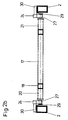
- a lane 1 for skids is designed as a roller conveyor 3, over which the skids 2 are moved, for example, at a conveying speed of two meters per second.
- the skid 2 which carries an inner frame 4 (cf. FIG. 2a), is moved via rollers 6 along the roller conveyor 3.
- lateral guide rollers 7 are provided on the road 1, through which the skid can be transported along the road 1.
- the skid 2 carries transverse stiffeners 8 (cf. FIG. 1 b).
- the skid 2 is driven by two rollers 9, which are driven by a toothed belt interacting with a motor 16, and which roll on one longitudinal side 12 of the skid 2 and spring-loaded counter rollers 11, which roll on a different longitudinal side 13 of the skid 2.
- a toothed belt drive of the rollers 9 shown in the exemplary embodiment it can also be driven via chains which are driven by a motor.
- the toothed belt can also roll directly on the long side 12 as a rollable drive.
- These can also be replaced, for example, by a spring-mounted toothed belt that rolls on the long side 13.
- a reversal in the resilient support is also possible, in such a way that the driven rollers 9 are spring-mounted and the counter-rollers 11 are rigidly attached.
- timing belts can also be used alone
- the rollable counter-holder 11, which lies opposite the rollers 9, makes it possible to prevent the skids from evading when the rollers 9 are pressed on. This makes it possible to transmit the full acceleration forces to the long sides 12, 13 of the skids.
- the roadway 1 is according to embodiment Fig. La on supports 15 and it is thus possible that a drive motor 16, which is designed, for example, as a geared motor, drives down the rollers 9 via the toothed belt drive, without the top of the skid 2 being pushed through it Drive motor is interrupted.
- a drive motor 16 which is designed, for example, as a geared motor, drives down the rollers 9 via the toothed belt drive, without the top of the skid 2 being pushed through it Drive motor is interrupted.
- Such a configuration gives greater freedom in machining, in particular in the case of projecting components, and opens up the possibility of arranging the drive of the rollers 9 and the rolling rollers 11 as a counter-holder at any point on the roadway, for example also at the point at which a dissolution of the Skids 2 transported step by step from processing station to processing station take place in a single-skid conveyance, without additional conversions being necessary.
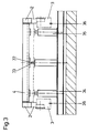
- the inner frame 4 shown in FIGS. 2a to d consists of cross members 17 and side members 18.
- an additional stiffener 19 is provided between the side members 18 to stabilize the inner frame 4.
- Ends 20, 21 and 22, 23 of the cross members 17 are resiliently supported in receptacles 24 which are arranged on the skid 2.
- the recordings can be made of steel springs or Rubber springs exist. It is also possible to provide a steel-rubber spring in which the steel essentially represents the reinforcement.
- the skid carries collar rollers 25 and can thus be moved with a fixed, not shown, rail track, likewise with the rollers 9 driven by the toothed belt drive and the rollable counter-holder 11.
- the section through the skid 2 shown in FIG. 2b shows how the ends 20, 21 and 22, 23 are floating in the receptacles 24, which are arranged on the skid 2.
- Springs 27 form the side walls of the receptacles 24, while a transverse spring 29 (cf. FIG. 2d) extends conically as the rear wall away from the skid 2, but is fastened to the receptacle 24.
- the transverse spring 29 is not connected to the springs 27, but only to a holder 30 of the receptacle 24. This makes it possible for the inner frame 4 to be supported in a floating manner against the transverse spring 29 during transverse movements and one in the conveying direction when the skid 2 is accelerated or decelerated floating storage of the inner frame is ensured by the springs 27.
- the skid provided with a component can thus dampen both the accelerations and the decelerations without the position taken being changed by the frame colliding against one another.
- the holder 30 is connected to the respective skid by screwing on interchangeable skids 2 or by welding on permanently assigned skids 2 .
- the receiving structure which consists of springs 27, a transverse spring 29 and a receiving base 31, can also be designed as a welded construction together with the holder 30.
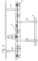
- FIG. 3 shows a centering station in which, by lowering the skid 2, the inner frame 4, which is connected to it in a certain position but is floating, slides onto a centering mandrel 33 with a centering hole 32 arranged on the inner frame 4.
- the roller conveyor 3 is lowered in the direction of arrows 36 during centering.
- no further centering aids have to be attached to the centering station between the centering mandrel and the centering bore, which leads to a considerable simplification and to a flat construction of the entire transfer line.
- the hanging arrangement of the conveying device shown in FIG. 4 shows an inner frame 4 which is arranged hanging on the skid 2 via supports 42, the roller conveyor 3 being arranged as a conveying track via ceiling supports 41 on the ceiling of a production site.
- ceiling supports 41 are arranged on the outside of the roller conveyor 3, while the supports 42 supporting the inner frame 4 are arranged inside the skid 2.
Claims (16)
Priority Applications (2)
| Application Number | Priority Date | Filing Date | Title |
|---|---|---|---|
| DE8585101383T DE3564245D1 (en) | 1985-02-09 | 1985-02-09 | Method and device for conveying and centering a vehicle |
| EP19850101383 EP0191116B2 (fr) | 1985-02-09 | 1985-02-09 | Procédé et dispositif de transport et de centrage d'un véhicule |
Applications Claiming Priority (1)
| Application Number | Priority Date | Filing Date | Title |
|---|---|---|---|
| EP19850101383 EP0191116B2 (fr) | 1985-02-09 | 1985-02-09 | Procédé et dispositif de transport et de centrage d'un véhicule |
Publications (3)
| Publication Number | Publication Date |
|---|---|
| EP0191116A1 EP0191116A1 (fr) | 1986-08-20 |
| EP0191116B1 EP0191116B1 (fr) | 1988-08-10 |
| EP0191116B2 true EP0191116B2 (fr) | 1992-07-15 |
Family
ID=8193291
Family Applications (1)
| Application Number | Title | Priority Date | Filing Date |
|---|---|---|---|
| EP19850101383 Expired - Lifetime EP0191116B2 (fr) | 1985-02-09 | 1985-02-09 | Procédé et dispositif de transport et de centrage d'un véhicule |
Country Status (2)
| Country | Link |
|---|---|
| EP (1) | EP0191116B2 (fr) |
| DE (1) | DE3564245D1 (fr) |
Families Citing this family (5)
| Publication number | Priority date | Publication date | Assignee | Title |
|---|---|---|---|---|
| SE461518B (sv) * | 1987-09-16 | 1990-02-26 | Dinol Ab | Flytande ram |
| ES2075926T3 (es) * | 1991-11-14 | 1995-10-16 | Schenck Ag Carl | Cinta de placas para la marcha en curva. |
| DE4330183B4 (de) * | 1993-09-01 | 2004-10-28 | Siemens Ag | Fördereinrichtung zum Transport von Plattformen |
| DE50207029D1 (de) | 2002-12-09 | 2006-07-06 | Siemens Ag | Hubtisch in Förderstrassen für Transporteinrichtungen |
| CN110466964A (zh) * | 2019-09-18 | 2019-11-19 | 湖北猛程智能装备股份有限公司 | 一种用于汽车装配线输送系统的浮动式转接对接装置 |
Family Cites Families (3)
| Publication number | Priority date | Publication date | Assignee | Title |
|---|---|---|---|---|
| DE2100842C3 (de) * | 1971-01-09 | 1974-04-25 | Rene Blaser, Hebe- Und Foerderanlagen, Maschinenbau, Luzern (Schweiz) | Anlage zum Fördern von in Behälterwagen befindlichem Gut |
| DE3147784C2 (de) * | 1981-12-03 | 1984-10-11 | Audi Nsu Auto Union Ag, 7107 Neckarsulm | Fördervorrichtung für eine Transferstraße |
| DE3316050A1 (de) * | 1983-05-03 | 1984-11-08 | Friedrich Deckel AG, 8000 München | Einrichtung zum transport von werkstueckpaletten |
-
1985
- 1985-02-09 DE DE8585101383T patent/DE3564245D1/de not_active Expired
- 1985-02-09 EP EP19850101383 patent/EP0191116B2/fr not_active Expired - Lifetime
Also Published As
| Publication number | Publication date |
|---|---|
| EP0191116A1 (fr) | 1986-08-20 |
| DE3564245D1 (en) | 1988-09-15 |
| EP0191116B1 (fr) | 1988-08-10 |
Similar Documents
| Publication | Publication Date | Title |
|---|---|---|
| EP0252871B1 (fr) | Robot industriel | |
| DE3331469C2 (de) | Anlage zum automatischen Positionieren und Schweißen von Fahrzeugkarosserien sowie Fahrzeugrohkarosserie, hergestellt auf einer solchen Anlage | |
| AT393819B (de) | Foerdereinrichtung fuer werkstuecke bzw. werkstuecktraeger, insbesondere fuer eine montagemaschine | |
| CH681001A5 (fr) | ||
| DE2063309A1 (de) | Fordervorrichtung fur Fertigungs straßen | |
| DE2402665A1 (de) | Einrichtung zum fertigen aus bauelementen bestehenden erzeugnissen, insbesondere personenkraftwagen | |
| DE2314794A1 (de) | Vorrichtung fuer den vertikalen transport von koerpern | |
| DE102012009063A1 (de) | Speichereinheit für Trägersysteme | |
| DE3712510C2 (fr) | ||
| DE3230455A1 (de) | Vorrichtung zum schweissen von karosserien fuer kraftfahrzeuge | |
| DE3316050C2 (fr) | ||
| DE102012009061A1 (de) | Bearbeitungsanlage für Baueinheiten | |
| EP0063253A2 (fr) | Dispositif pour aligner et centrer automatiquement des pièces à usiner | |
| EP0361179A2 (fr) | Dispositif de positionnement pour le transfert précis de pièces entre un chariot de transport et une installation fixe | |
| EP0191116B2 (fr) | Procédé et dispositif de transport et de centrage d'un véhicule | |
| DE2839496A1 (de) | Verfahren und vorrichtung zum uebergeben von foerdergut von einem schienengebundenen angetriebenen rollenfoerderer auf einen als lagerplatz ausgebildeten, antreibbaren rollenfoerderer mit reibschluss | |
| DE102014010556B4 (de) | Antriebswagen für eine Transporteinrichtung sowie Transportsystem | |
| DE10064523A1 (de) | Anlage zur Bearbeitung von Werkstücken | |
| EP0405471A1 (fr) | Chariot à roulettes pour emmagasiner et sortir des plateaux de chargement | |
| DE602004003320T2 (de) | Vorrichtung zum Zuführen und Entfernen der Wagen von Fliesen zu/von Lade- und Entlademaschine | |
| DE10028106A1 (de) | Vorrichtung zum Transportieren eines Gegenstandes oder einer Gegenstandsgruppe | |
| DE3448491C2 (de) | Fördereinrichtung, insbesondere für eine Montagemaschine | |
| DE2601030C3 (de) | Vorrichtung zum Legen von Strängen einer Kittmasse o. dgl. | |
| DE4328983C2 (de) | Anlage für die Bearbeitung und/oder Montage von auf einem Werkstückträger angeordneten Werkstücken | |
| DE7138120U (de) | Vorrichtung zum Transport von Werkstücken und in losen Werkstückaufnahmen eingelegten Werkstücken von einer Beladesteiie zu Bearbeitungsplätzen bzw. Mascninen und von diesen zu einer Entladestelle |
Legal Events
| Date | Code | Title | Description |
|---|---|---|---|
| PUAI | Public reference made under article 153(3) epc to a published international application that has entered the european phase |
Free format text: ORIGINAL CODE: 0009012 |
|
| 17P | Request for examination filed |
Effective date: 19851127 |
|
| AK | Designated contracting states |
Kind code of ref document: A1 Designated state(s): AT BE CH DE FR GB IT LI LU NL SE |
|
| RBV | Designated contracting states (corrected) |
Designated state(s): DE FR IT |
|
| 17Q | First examination report despatched |
Effective date: 19870601 |
|
| ITF | It: translation for a ep patent filed |
Owner name: ING. ZINI MARANESI & C. S.R.L. |
|
| GRAA | (expected) grant |
Free format text: ORIGINAL CODE: 0009210 |
|
| AK | Designated contracting states |
Kind code of ref document: B1 Designated state(s): DE FR IT |
|
| REF | Corresponds to: |
Ref document number: 3564245 Country of ref document: DE Date of ref document: 19880915 |
|
| ET | Fr: translation filed | ||
| PLBI | Opposition filed |
Free format text: ORIGINAL CODE: 0009260 |
|
| 26 | Opposition filed |
Opponent name: MANNESMANN AKTIENGESELLSCHAFT Effective date: 19890502 |
|
| ITF | It: translation for a ep patent filed |
Owner name: ING. ZINI MARANESI & C. S.R.L. |
|
| PUAH | Patent maintained in amended form |
Free format text: ORIGINAL CODE: 0009272 |
|
| STAA | Information on the status of an ep patent application or granted ep patent |
Free format text: STATUS: PATENT MAINTAINED AS AMENDED |
|
| 27A | Patent maintained in amended form |
Effective date: 19920715 |
|
| AK | Designated contracting states |
Kind code of ref document: B2 Designated state(s): DE FR IT |
|
| ET3 | Fr: translation filed ** decision concerning opposition | ||
| ITTA | It: last paid annual fee | ||
| PGFP | Annual fee paid to national office [announced via postgrant information from national office to epo] |
Ref country code: FR Payment date: 19940114 Year of fee payment: 10 |
|
| PG25 | Lapsed in a contracting state [announced via postgrant information from national office to epo] |
Ref country code: FR Effective date: 19951031 |
|
| REG | Reference to a national code |
Ref country code: FR Ref legal event code: ST |
|
| PGFP | Annual fee paid to national office [announced via postgrant information from national office to epo] |
Ref country code: DE Payment date: 20040226 Year of fee payment: 20 |