EP0188071B1 - Atmungssynchronisiertes Gerät zur Zufuhr von konzentriertem Sauerstoff - Google Patents
Atmungssynchronisiertes Gerät zur Zufuhr von konzentriertem Sauerstoff Download PDFInfo
- Publication number
- EP0188071B1 EP0188071B1 EP85308311A EP85308311A EP0188071B1 EP 0188071 B1 EP0188071 B1 EP 0188071B1 EP 85308311 A EP85308311 A EP 85308311A EP 85308311 A EP85308311 A EP 85308311A EP 0188071 B1 EP0188071 B1 EP 0188071B1
- Authority
- EP
- European Patent Office
- Prior art keywords
- oxygen
- inhalation
- enriched gas
- gas
- breath
- Prior art date
- Legal status (The legal status is an assumption and is not a legal conclusion. Google has not performed a legal analysis and makes no representation as to the accuracy of the status listed.)
- Expired
Links
- 239000001301 oxygen Substances 0.000 title claims description 176
- 229910052760 oxygen Inorganic materials 0.000 title claims description 176
- QVGXLLKOCUKJST-UHFFFAOYSA-N atomic oxygen Chemical compound [O] QVGXLLKOCUKJST-UHFFFAOYSA-N 0.000 claims description 158
- 239000007789 gas Substances 0.000 claims description 112
- 238000001179 sorption measurement Methods 0.000 claims description 78
- 230000029058 respiratory gaseous exchange Effects 0.000 claims description 49
- 238000010926 purge Methods 0.000 claims description 17
- 210000002345 respiratory system Anatomy 0.000 claims description 3
- 238000012935 Averaging Methods 0.000 claims 1
- 230000015654 memory Effects 0.000 description 26
- 230000000241 respiratory effect Effects 0.000 description 24
- MYMOFIZGZYHOMD-UHFFFAOYSA-N Dioxygen Chemical compound O=O MYMOFIZGZYHOMD-UHFFFAOYSA-N 0.000 description 21
- 229910001882 dioxygen Inorganic materials 0.000 description 21
- IJGRMHOSHXDMSA-UHFFFAOYSA-N Atomic nitrogen Chemical compound N#N IJGRMHOSHXDMSA-UHFFFAOYSA-N 0.000 description 16
- 239000003463 adsorbent Substances 0.000 description 13
- 238000000034 method Methods 0.000 description 12
- 230000003584 silencer Effects 0.000 description 12
- 239000012528 membrane Substances 0.000 description 8
- 229910052757 nitrogen Inorganic materials 0.000 description 8
- 238000011282 treatment Methods 0.000 description 8
- 230000004044 response Effects 0.000 description 6
- 230000008859 change Effects 0.000 description 5
- 230000007423 decrease Effects 0.000 description 4
- 238000003795 desorption Methods 0.000 description 4
- 238000010586 diagram Methods 0.000 description 4
- 230000000694 effects Effects 0.000 description 4
- 230000006870 function Effects 0.000 description 4
- 230000007794 irritation Effects 0.000 description 4
- 210000000056 organ Anatomy 0.000 description 4
- 230000009467 reduction Effects 0.000 description 4
- 241000894006 Bacteria Species 0.000 description 3
- 230000005856 abnormality Effects 0.000 description 3
- 230000008901 benefit Effects 0.000 description 3
- 230000007246 mechanism Effects 0.000 description 3
- 238000012545 processing Methods 0.000 description 3
- 230000008929 regeneration Effects 0.000 description 3
- 238000011069 regeneration method Methods 0.000 description 3
- 238000005070 sampling Methods 0.000 description 3
- 239000000126 substance Substances 0.000 description 3
- 210000003437 trachea Anatomy 0.000 description 3
- 239000008280 blood Substances 0.000 description 2
- 210000004369 blood Anatomy 0.000 description 2
- 230000001276 controlling effect Effects 0.000 description 2
- 125000004122 cyclic group Chemical group 0.000 description 2
- 238000004519 manufacturing process Methods 0.000 description 2
- 238000012549 training Methods 0.000 description 2
- 239000013585 weight reducing agent Substances 0.000 description 2
- 206010002091 Anaesthesia Diseases 0.000 description 1
- 208000003443 Unconsciousness Diseases 0.000 description 1
- 230000003321 amplification Effects 0.000 description 1
- 230000037005 anaesthesia Effects 0.000 description 1
- 230000015572 biosynthetic process Effects 0.000 description 1
- 230000001684 chronic effect Effects 0.000 description 1
- 238000010276 construction Methods 0.000 description 1
- 230000003247 decreasing effect Effects 0.000 description 1
- 238000009795 derivation Methods 0.000 description 1
- 238000001514 detection method Methods 0.000 description 1
- 230000006866 deterioration Effects 0.000 description 1
- 238000010790 dilution Methods 0.000 description 1
- 239000012895 dilution Substances 0.000 description 1
- 201000010099 disease Diseases 0.000 description 1
- 208000037265 diseases, disorders, signs and symptoms Diseases 0.000 description 1
- 239000006185 dispersion Substances 0.000 description 1
- 238000009826 distribution Methods 0.000 description 1
- 229940079593 drug Drugs 0.000 description 1
- 239000003814 drug Substances 0.000 description 1
- 239000000428 dust Substances 0.000 description 1
- 230000008030 elimination Effects 0.000 description 1
- 238000003379 elimination reaction Methods 0.000 description 1
- 238000005265 energy consumption Methods 0.000 description 1
- 238000001595 flow curve Methods 0.000 description 1
- 238000001727 in vivo Methods 0.000 description 1
- 238000002664 inhalation therapy Methods 0.000 description 1
- 238000003780 insertion Methods 0.000 description 1
- 230000037431 insertion Effects 0.000 description 1
- 230000003434 inspiratory effect Effects 0.000 description 1
- 230000033001 locomotion Effects 0.000 description 1
- 230000007257 malfunction Effects 0.000 description 1
- 238000005259 measurement Methods 0.000 description 1
- 239000000203 mixture Substances 0.000 description 1
- 230000004048 modification Effects 0.000 description 1
- 238000012986 modification Methods 0.000 description 1
- 238000012544 monitoring process Methods 0.000 description 1
- 238000003199 nucleic acid amplification method Methods 0.000 description 1
- 230000008520 organization Effects 0.000 description 1
- 229940116073 oxygen gas for inhalation Drugs 0.000 description 1
- 238000006213 oxygenation reaction Methods 0.000 description 1
- 230000008569 process Effects 0.000 description 1
- 230000007420 reactivation Effects 0.000 description 1
- 230000001172 regenerating effect Effects 0.000 description 1
- 230000001105 regulatory effect Effects 0.000 description 1
- 230000033764 rhythmic process Effects 0.000 description 1
- 230000002269 spontaneous effect Effects 0.000 description 1
- 230000000638 stimulation Effects 0.000 description 1
- 230000001629 suppression Effects 0.000 description 1
- 238000012360 testing method Methods 0.000 description 1
- 238000011144 upstream manufacturing Methods 0.000 description 1
Images


Classifications
-
- A—HUMAN NECESSITIES
- A61—MEDICAL OR VETERINARY SCIENCE; HYGIENE
- A61M—DEVICES FOR INTRODUCING MEDIA INTO, OR ONTO, THE BODY; DEVICES FOR TRANSDUCING BODY MEDIA OR FOR TAKING MEDIA FROM THE BODY; DEVICES FOR PRODUCING OR ENDING SLEEP OR STUPOR
- A61M16/00—Devices for influencing the respiratory system of patients by gas treatment, e.g. mouth-to-mouth respiration; Tracheal tubes
- A61M16/0051—Devices for influencing the respiratory system of patients by gas treatment, e.g. mouth-to-mouth respiration; Tracheal tubes with alarm devices
-
- A—HUMAN NECESSITIES
- A61—MEDICAL OR VETERINARY SCIENCE; HYGIENE
- A61M—DEVICES FOR INTRODUCING MEDIA INTO, OR ONTO, THE BODY; DEVICES FOR TRANSDUCING BODY MEDIA OR FOR TAKING MEDIA FROM THE BODY; DEVICES FOR PRODUCING OR ENDING SLEEP OR STUPOR
- A61M16/00—Devices for influencing the respiratory system of patients by gas treatment, e.g. mouth-to-mouth respiration; Tracheal tubes
- A61M16/021—Devices for influencing the respiratory system of patients by gas treatment, e.g. mouth-to-mouth respiration; Tracheal tubes operated by electrical means
- A61M16/022—Control means therefor
- A61M16/024—Control means therefor including calculation means, e.g. using a processor
-
- A—HUMAN NECESSITIES
- A61—MEDICAL OR VETERINARY SCIENCE; HYGIENE
- A61M—DEVICES FOR INTRODUCING MEDIA INTO, OR ONTO, THE BODY; DEVICES FOR TRANSDUCING BODY MEDIA OR FOR TAKING MEDIA FROM THE BODY; DEVICES FOR PRODUCING OR ENDING SLEEP OR STUPOR
- A61M16/00—Devices for influencing the respiratory system of patients by gas treatment, e.g. mouth-to-mouth respiration; Tracheal tubes
- A61M16/06—Respiratory or anaesthetic masks
- A61M16/0666—Nasal cannulas or tubing
- A61M16/0672—Nasal cannula assemblies for oxygen therapy
- A61M16/0677—Gas-saving devices therefor
-
- A—HUMAN NECESSITIES
- A61—MEDICAL OR VETERINARY SCIENCE; HYGIENE
- A61M—DEVICES FOR INTRODUCING MEDIA INTO, OR ONTO, THE BODY; DEVICES FOR TRANSDUCING BODY MEDIA OR FOR TAKING MEDIA FROM THE BODY; DEVICES FOR PRODUCING OR ENDING SLEEP OR STUPOR
- A61M16/00—Devices for influencing the respiratory system of patients by gas treatment, e.g. mouth-to-mouth respiration; Tracheal tubes
- A61M16/10—Preparation of respiratory gases or vapours
- A61M16/1005—Preparation of respiratory gases or vapours with O2 features or with parameter measurement
- A61M16/101—Preparation of respiratory gases or vapours with O2 features or with parameter measurement using an oxygen concentrator
-
- A—HUMAN NECESSITIES
- A61—MEDICAL OR VETERINARY SCIENCE; HYGIENE
- A61M—DEVICES FOR INTRODUCING MEDIA INTO, OR ONTO, THE BODY; DEVICES FOR TRANSDUCING BODY MEDIA OR FOR TAKING MEDIA FROM THE BODY; DEVICES FOR PRODUCING OR ENDING SLEEP OR STUPOR
- A61M16/00—Devices for influencing the respiratory system of patients by gas treatment, e.g. mouth-to-mouth respiration; Tracheal tubes
- A61M16/0057—Pumps therefor
- A61M16/0063—Compressors
-
- A—HUMAN NECESSITIES
- A61—MEDICAL OR VETERINARY SCIENCE; HYGIENE
- A61M—DEVICES FOR INTRODUCING MEDIA INTO, OR ONTO, THE BODY; DEVICES FOR TRANSDUCING BODY MEDIA OR FOR TAKING MEDIA FROM THE BODY; DEVICES FOR PRODUCING OR ENDING SLEEP OR STUPOR
- A61M16/00—Devices for influencing the respiratory system of patients by gas treatment, e.g. mouth-to-mouth respiration; Tracheal tubes
- A61M16/10—Preparation of respiratory gases or vapours
- A61M16/105—Filters
- A61M16/1055—Filters bacterial
-
- A—HUMAN NECESSITIES
- A61—MEDICAL OR VETERINARY SCIENCE; HYGIENE
- A61M—DEVICES FOR INTRODUCING MEDIA INTO, OR ONTO, THE BODY; DEVICES FOR TRANSDUCING BODY MEDIA OR FOR TAKING MEDIA FROM THE BODY; DEVICES FOR PRODUCING OR ENDING SLEEP OR STUPOR
- A61M16/00—Devices for influencing the respiratory system of patients by gas treatment, e.g. mouth-to-mouth respiration; Tracheal tubes
- A61M16/10—Preparation of respiratory gases or vapours
- A61M16/105—Filters
- A61M16/106—Filters in a path
- A61M16/107—Filters in a path in the inspiratory path
-
- A—HUMAN NECESSITIES
- A61—MEDICAL OR VETERINARY SCIENCE; HYGIENE
- A61M—DEVICES FOR INTRODUCING MEDIA INTO, OR ONTO, THE BODY; DEVICES FOR TRANSDUCING BODY MEDIA OR FOR TAKING MEDIA FROM THE BODY; DEVICES FOR PRODUCING OR ENDING SLEEP OR STUPOR
- A61M16/00—Devices for influencing the respiratory system of patients by gas treatment, e.g. mouth-to-mouth respiration; Tracheal tubes
- A61M16/0003—Accessories therefor, e.g. sensors, vibrators, negative pressure
- A61M2016/0015—Accessories therefor, e.g. sensors, vibrators, negative pressure inhalation detectors
- A61M2016/0018—Accessories therefor, e.g. sensors, vibrators, negative pressure inhalation detectors electrical
- A61M2016/0021—Accessories therefor, e.g. sensors, vibrators, negative pressure inhalation detectors electrical with a proportional output signal, e.g. from a thermistor
-
- A—HUMAN NECESSITIES
- A61—MEDICAL OR VETERINARY SCIENCE; HYGIENE
- A61M—DEVICES FOR INTRODUCING MEDIA INTO, OR ONTO, THE BODY; DEVICES FOR TRANSDUCING BODY MEDIA OR FOR TAKING MEDIA FROM THE BODY; DEVICES FOR PRODUCING OR ENDING SLEEP OR STUPOR
- A61M2205/00—General characteristics of the apparatus
- A61M2205/42—Reducing noise
Definitions
- This invention relates to a breath-synchronized concentrated-oxygen supplier, and more particularly to an apparatus which supplies oxygen-enriched gas to a patient in synchronism with the inhalation phase of his respiration.
- oxygen concentrators have been used in inhalation therapy for patients suffering from respiratory ailment or circulatory diseases.
- oxygen concentrators for home use have become remarkably popular these days, because they are capable of concentrating the oxygen gas in air by the use of a household electric power source through a simple operation, and supplying such concentrated oxygen gas for medical use.
- ANSI American National Standard Institute
- FDA Federal Food and Drug Administration
- an international standard for it e.g., International Organization for Standardization ISO 5059, is now ready to be published.
- such oxygen concentrators are used to eliminate the inconvenience involved in the conventional oxygen distribution by use of heavy pressure vessels such as gas cylinders.
- the closed circuit method uses a «facemask apparatus» on the face or an endotracheal tube inserted into the trachea of the patient and supplies the gas to the patient through a passage, which is airtightly separated from the atmosphere and extends between the breathing device, i.e., the respirator or the gas supply system, and the patient's respiratory system.
- This closed circuit method has an advantage in its high inhaling efficiency, because the gas can be inhaled at about the same concentration as that of the gas supplied to the closed passage and the patient's breathing can be assisted or adjusted by regulating the pressure of the gas inside.
- the closed circuit method has a shortcoming in that it may cause irritation or discomfort on the side of the patient because of the covering of his mouth and nose and the direct insertion of foreign substance in his trachea. Accordingly, the closed circuit method has been used mainly for seriously sick and unconscious patients or patients under anesthesia.
- the open circuit method uses a breathing passage which is open to the atmosphere.
- the tip of the gas supplying tube is inserted into the nostril or the mouth of the patient so as to feed the gas without using any airtight connection between the apparatus and the face or upper airway of the patient, and the irritation or discomfort on the side of the patient are reduced and the patient is allowed to speak, eat or drink during the inhalation treatment by this method.
- this open circuit method is mainly used for mild cases in which self-breathing is possible.
- oxygen or gas mixture for inhalation may be supplied in response to the patient's spontaneous breathing by detecting the gas pressure changes in the closed respiratory circuit, because the latter can be used as a triggering mechanism.
- the gas is supplied at a constant flow rate regardless of the patient's breathing. Accordingly, the gas is forced to the patient even during his exhalation and discomfort has been caused to the patient. Besides, a large part of the constantly fed gas is wasted because the gas supplied during patient's exhalation is discharged to the atmosphere without being used.
- the open circuit type breathing apparatus is susceptible to undue dilution of oxygen concentration with air because it is open to the atmosphere.
- it has been practiced to increase the flow rate of the constantly fed gas.
- the inventors have found that the transcutaneous tissue partial pressure of oxygen (tcPO z ) increases with the flow rate only up to 3 P/min, and the oxygenation in vivo hardly further increases even when the oxygen flow rate of insufflation. exceeds the above value, as shown in Table 1.
- the Japanese Patent Laying-open Publication No. 8,972/84 proposed a breath-synchronized open circuit type breathing system.
- oxygen gas is supplied only during inhalations of the patient, so that this type breathing system has advantages in that the patient's comfort is ensured during the inhalation treatment and that the oxygen concentrator can be made small due to the reduced use of oxygen.
- the oxygen concentrators can be classified into two types, i.e., the so-called membrane type and the so-called molecular adsorption type.
- the membrane type oxygen concentrator passes the air through a special membrane which transmits oxygen more easily than nitrogen, so that the oxygen concentration is enhanced by increasing the number of oxygen molecules relative to the number of nitrogen molecules. With this membrane type, the maximum attainable oxygen concentration is limited to about 40% at most.
- the membrane type concentrator is rather suitable for closed circuit type breathing system in which the oxygen gas is inhaled at about the same concentration as supplied by the oxygen concentrator.
- the air is passed through an adsorption cylinder filled with a special substance (adsorbent) while increasing and decreasing the air pressure, and nitrogen and moisture in the air are removed by repeated adsorption and desorption processes so as to produce highly concentrated oxygen.
- adsorbent a special substance
- nitrogen and moisture in the air are removed by repeated adsorption and desorption processes so as to produce highly concentrated oxygen.
- an oxygen concentration higher than 90% can be obtained.
- the molecular adsorption type concentrator is suitable for long inhalation treatments by using an open circuit type breathing system allowing the mixing of open air with the concentrated oxygen gas for inhalation.
- the molecular adsorption type has a shortcoming in that when the outflow of the oxygen- enriches gas increases, the amount of purge gas for regenerating the adsorbent decreases, resulting in a gradual reduction of the oxygen concentration of the oxygen-enriched output gas. Such reduction of the oxygen concentration is contrary to the very purpose of the oxygen concentrator. As a countermeasure, it has been tried to use oxygen concentrators of larger size and to improve their technical performance, but there have been certain limits in such trial.
- the Japanese Patent Application Publication No. 5,571/82 corresponding to U.S. Patent No. 4,331,455 proposes an oxygen concentrator using two adsorption cylinders, which cylinders are alternately operated in such a manner that during the adsorption cycle of one cylinder, a part of the oxygen-enriched output gas from that cylinder is used as the purge gas forthe other cylinder.
- Such oxygen concentrator with the two adsorption cylinders has an advantage in that, even when adsorption cylinders of comparatively small capacity are used, oxygen-enriched gas with a desired concentration can be produced over a long period of time with a high stability because the two cylinders are efficiently purged with each other.
- the respiration pattern of a human being or the like living body will be briefly reviewed now.
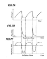
- the oxygen partial pressure in the arterial blood during the respiration can be effectively increased by providing a sufficiently high peak flow rate of oxygen at the beginning of the inhalation phase.
- the inhaled gas at the end portion of the inhalation phase does not reach the respiratory organ but fills up the so-called dead space portion, so that it is not used effectively in the respiratory organ.
- the efficiency of the oxygen-enriched gas usage in terms of its utilization factor can be improved by using such breath-synchronized control in which a sufficiently high peak flow rate of oxygen-enriched gas is superposed onto the initial portion of the steady state flow rate of such gas during the inhalation phase while the oxygen-enriched gas supply is interrupted at a certain end portion of the inhalation phase.
- the breath-synchronized open circuit type breathing system disclosed by the above-mentioned Japanese Patent Laying-open Publication No. 8,972/84 uses such control that a constant flow rate of the oxygen gas with a certain concentration is maintained during the inhalation phase and the interruption of the oxygen gas supply near the end of the inhalation phase is effected by a one-shot circuit which is actuated at the beginning of the inhalation phase, so that the oxygen is supplied for a predetermined period of time.
- the oxygen partial pressure of the blood may not be raised so effectively and the utilization rate of the oxygen gas may not be sufficiently high.
- the duration of oxygen gas supply for the inhalation phase is set at a certain value but is not variable in response to the patient's respiration, so that the breathing system cannot respond well to irregularity of the respiration and it may sometimes become out of synchronism with the patient's respiration, resulting in a still lower utilization rate.
- the respiration pattern of a human being inherently varies from person to person, and even for one person, the speed and magnitude of the respiration vary depending on circumstances. Even under the same conditions, actual measurements of the durations of individual inhalations and exhalations show dispersions.
- the timing and duration of the oxygen gas supply from the breathing system should be automatically controlled so as to be in synchronism with each of the ever varying inhalation timing and duration depending on the personal, circumstantial and individual respiratory differences.
- the oxygen concentrator disclosed in the above-mentioned Japanese Patent Laying-open Publication No. 5,571/82 produces an almost constant flow rate of the oxygen gas with a certain concentration, so that it has shortcomings in that its utilization rate in terms of usage by the living body may be relatively low and that it may still cause irritation and discomfort on the side of patients or the like.
- an object of the invention is to obviate the above-mentioned difficulties of the prior art by providing a novel breath-synchronized concentrated-oxygen supplier which is capable of increasing the utilization factor of oxygen-enriched gas, minimizing the irritation, respiratory resistance and discomfort on the side of patient or the like living body, and reducing the size, weight and energy consumption of the supplier.
- a preferred embodiment of the breath-synchronized concentrated-oxygen supplier according to the present invention uses an oxygen concentrator producing and storing oxygen-enriched gas, and a buffer tank which temporarily stores the oxygen-enriched gas from the oxygen concentrator.
- a valve is mounted on the outlet of the buffer tank so as to control the flow of the oxygen-enriched gas from the buffer tank toward the respiratory system of a living body through a path that is open to the atmosphere.
- a suitable sensor is exposed to respiration of the living body, so as to generate an output signal indicative of inhalation (inspiratory) phase and exhalation (expiratory) phase of the respiration.
- an input means is provided, so that a ratio between the entire length of the inhalation phase and a specific end portion thereof is set by an operator on the input means.
- the above valve is provided with such a regulator which is adapted to detect duration of each inhalation phase in succession based on the output signal from the sensor and, to open the valve at the beginning of each inhalation phase to keep the valve open for a period equivalent to an average of the preceding inhalation durations minus the portion corresponding to the above ratio set on the input means.
- the oxygen-enriched gas is supplied to the living body during each inhalation phase except the above specific end portion thereof.
- the above buffer tank acts to make the initial flow rate of the oxygen-enriched gas higher than the steady state flow rate thereof in each inhalation phase.
- the above-mentioned oxygen concentrator is formed of a reservoir tank, at least two compressor-driven adsorption cylinders, and a controller adapted to run at least one of said adsorption cylinders at a time for producing the oxygen-enriched gas for storing in said reservoir while a portion of the oxygen-enriched gas thus produced is blown into remaining adsorption cylinders at rest for purging.
- Each of the above compressor-driven adsorption cylinders may consist of an adsorption cylinder and a compressor directly connected thereto.
- the compressor-driven adsorption cylinders by connecting two or more adsorption cylinders to a common compressor through a selective valve.
- the selective valve may be a five-way valve adapted to connect one of said adsorption cylinders at a time to both said compressor and said exhaust passage.
- the concentrated-oxygen supplier of the invention uses a combination of an oxygen concentrator and a breath-synchronizing means.
- the respiration of a living body is detected, for instance by disposing a temperature sensor, preferably a thermocouple, in front of the nostril and monitoring the change in the electromotive force of the thermocouple due to the temperature change of the respiratory air so as to find the inhalation phase by the temperature reduction during that phase, and a valve is opened in synchronism with the detected inhalation phase for starting the supply of the oxygen-enriched gas as the beginning of the inhalation phase.
- a temperature sensor preferably a thermocouple
- the oxygen-enriched gas supply is interrupted during the exhalation phase, and this interruption causes the storing of the oxygen-enriched gas in a buffer tank at an elevated pressure. That elevated pressure facilitates the superposition of a pulse-like initial high flow rate onto the steady state flow rate of the oxygen-enriched gas when the above-mentioned valve is opened at the beginning of the inhalation phase.
- the duration in which the above valve is kept open is determined by a regulator based on a combination of average duration of the preceding inhalation phases as determined by the output from the sensor and the ratio set on the input means from the outside.
- the oxygen-enriched gas supply is interrupted with such a timing that the oxygen-enriched gas is not supplied at that end portion of the inhalation phase in which the inhaled gas is filled in the dead space without being used.
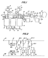
- 1, 61 are oxygen concentrators
- 2 is a reservoir tank
- 3, 4 are adsorption cylinders
- 5, 7 are air cleaners
- 6, are compressors
- 9, 10 are one-way valves
- 11 is an orifice
- 12, 13 are pressure switches
- 14, 15 are solenoid-operated release valves
- 16 is a silencer
- 17 is a controller
- 18 is a shutout solenoid valve
- 19 is a reducing valve
- 20 is a bacteria filter
- 21 is a flow meter
- 22 is a patient
- 23 is a buffer tank
- 24 is a breath-synchronizing solenoid valve
- 25 is a humidifier
- 26 is a nasal cannula
- 27 is an oxygen analyzer
- 28 is a thermocouple
- 29 is a gas-supply regulator
- 31,32 are power source terminals
- 33, 34, 35 are relays
- 41 is a differential amplifier
- 42, 43, 44 are operational amplifiers
- 45 is a
- an oxygen concentrator 1 consists of one reservoir tank 2 and two adsorption cylinders 3 and 4.
- the adsorption cylinder 3 is connected to a compressor 6 with an air cleaner 5, so that after being treated by the air cleaner 5 for dust removal the air is compressed by the compressor 6 and the compressed air is delivered to the adsorption cylinder 3.
- the other adsorption cylinder 4 is connected to a compressor 8 with an air cleaner 7, so that compressed air from the compressor 8 is delivered to the adsorption cylinder 4.
- the adsorption cylinders 3 and 4 are connected to the reservoir tank 2 through one-way valves 9 and 10 respectively, and the two cylinders 3 and 4 are also communicated to each other through an orifice 11, so that the oxygen-enriched gas produced by one adsorption cylinder 3 or 4 is fed to the reservoir tank 2 through the corresponding one-way valve 9 or 10 while a part of such gas is directed on the other adsorption cylinder 4 or 3 through the orifice 11 as purge gas.
- Pressure switches 12 and 13 are mounted on the input side passages of the adsorption cylinders 3 and 4 respectively, while the input sides of the adsorption cylinders 3 and 4 are also connected to a common silencer 16 through solenoid-operated release valves 14 and 15 respectively.
- the output side of the silencer 16 is open to the atmosphere.
- a controller 17 is connected to the pressure switches 12, 13 and the release valves 14, 15. The controller 17 responds to signals from the pressure switches 12, 13 so as to control the operations of the compressors 6, 8, which are preferably in linear motortype for generating oxygen-enriched gas therein in an alternate manner.
- the controller 17 also controls the release valves 14 and 15, so that substances separated from the adsorbent in the adsorption cylinders 3 or 4 by the purge gas are discharged to the atmosphere together with the purge gas through the release valves 14 or 15 and the silencer 16.
- a shutout solenoid valve 18 is mounted on the output side passage of the reservoir tank 2. This valve 18 is closed when the concentrated oxygen supplier is at rest while it is kept open when the supplier is in operation, so that the oxygen-enriched gas is stored in the reservoir tank 2 during the rest period of the concentrated-oxygen supplier. Whereby, the reservoir tank 2 is kept ready for immediate operation when the supplier is restarted.
- the pressure of the oxygen-enriched gas delivered through the shutout solenoid valve 18 is reduced to a proper level for inhalation treatment by a reducing valve 19, and the gas is purified by a bacteria filter 20 and its flow rate is adjusted at a level suitable for a patient 22 by a flow meter 21 having a needle valve type adjusting mechanism.
- the gas is then applied to a buffer tank 23, and a breath-synchronizing solenoid valve 24 controls the gas stream from the buffer tank 23 to a patient 22through a humidifier 25 and a nasal cannula 26.
- the humidifier 25 gives a proper humidity to the oxygen-enriched gas so as to make it suitable for inhalation treatment of the patient 22.
- An oxygen analyzer 27 may be provided at a suitable position between the shutout solenoid valve 18 and the breath-synchronizing solenoid valve 24, so as to facilitate the detection of any malfunction of the oxygen concentrator 1, especially abnormality of the adsorbent, by operators such as medical doctors and nurses.
- the oxygen analyzer 27 is provided between the bacteria filter 20 and the flow meter 21 as shown in Fig. 1.
- thermocouple 28 mounted on the nasal cannula 26 in such a manner that the thermocouple 28 is exposed to the respiratory air flow through the patient's nostril.
- the output from the thermocouple 28 is applied to a gas-supply regulator 29 which controls the operation of the breath-synchronizing solenoid valve 24 based on the information from the thermocouple 28.
- Fig. 2 shows a sequential circuit diagram of the controller 17 of Fig. 1.
- Each of the pressure switches 12 and 13 has three terminals; namely, a common contact COM connected to a fixed end of a swingable blade 12a or 13a, and two terminals H and L with which the free end of the swingable blade 12a or 13a selectively comes in contact.
- the swingable blade 12a (13a) is kept in contact with the terminal H, while the swingable blade 12a (13a) is kept in contact with the terminal L as long as the above pressure is below the above predetermined value.
- the terminal COM of the pressure switch 12 is connected to one power source terminal 31 while the terminal COM of the pressure switch 13 is connected to another power source terminal 32.
- the power source terminals 31 and 32 are connected to a suitable control power source (not shown).
- a relay 33 is provided between the terminal H of the pressure switch 12 and the terminal L of the other pressure switch 13.
- the relay 33 has two normally open relay contacts 33-1 and 33-3 and one normally closed relay contact 33-2.
- the normally open relay contact 33-1 is connected between the relay 33 and the power source terminal 31 as a self-hold contact for the relay 33.
- the normally closed relay contact 33-2 is serially connected to a relay 34, and the serial circuit of the relay contact 33-2 and the relay 34 is connected across the power source terminals 31 and 32.
- the normally open relay contact 33-3 is serially connected to a relay 35, and the serial circuit of the relay contact 33-3 and the relay 35 is also connected across the power source terminals 31 and 32.
- the relay 34 has a normally open relay contact 34-1, which contact is connected between one power source terminal 31 and one joint of a parallel combination of the compressor 6 and the solenoid-operated release valve 15, the parallel combination having its opposite joint connected to the other power source terminal 32.
- the relay 35 has a normally open relay contact 35-1, which contact is connected between one power source terminal 31 and one joint of a parallel combination of the compressor 8 and the solenoid-operated release valve 14, the parallel combination having its opposite joint connected to the other power source terminal 32.
- Fig. 3 shows the electric circuit of the gas-supply regulator 29 of Fig. 1.
- the output from the thermocouple 28 acting as a sensor of respiration is applied to a differential amplifier 41 of the regulator 29.
- Operational amplifiers 42 and 43 of the differential amplifier 41 amplify the input from the thermocouple 28 and apply their output to an output stage operational amplifier 44 having a variable resistor 45 for gain adjustment.
- the output from the operational amplifier 44 is applied to a low-pass filter 46 for eliminating high-frequency noise and then converted into digital signals by an A/D converter 47, which digital signals are applied to an operational control unit 48.
- the control unit 48 has a central processing unit (CPU) 49, a timer 50, and memories 51 through 54.
- the CPU 49 is connected to an outside input means 55, such as a keyboard, through which means a ratio between the duration of an inhalation phase and the length of a specific end portion thereof is applied to the CPU 49 as an input information.
- the gas-supply regulator 29 has a foolproof mechanism; namely, the above-mentioned ratio of a desired magnitude can be accepted only when it falls within a certain predetermined range, lest a wild input at the outside input means 55 by a mistake should cause a total stop of the oxygen-enriched gas supply.
- the timer 50 has three functions; namely, a function of applying interruption signals to the CPU 49 for sampling the output from the A/D converter 47 at certain intervals, e.g., at every 10 msec in the illustrated embodiment, a function of measuring the open time of the breath-synchronizing solenoid valve 24 in the inhalation phase, and a function of measuring the duration of individual inhalation phases and exhalation phases.
- the memory 51 stores the data of preceding sampling, which sampling is effected in succession in a cyclic manner by the CPU 49.
- the memory 52 stores flags for indentifying the inhalation phase and the exhalation phase, e.g., a bit «1 for the inhalation phase and a bit «0» for the exhalation phase as in the case of the illustrated embodiment.
- the memory 53 stores time data on inhalation phases of the immediately preceding six normal respiratory motions while updating them.
- the memory 54 stores a program for controlling the operational control unit 48.
- the CPU 49 of the illustrated embodiment carries out the operations as instructed by the program from the memory 54 based on the data from the A/D converter 47, the time data on the past six normal inhalation phases as stored in the memory 53, and the data from the outside input means 55, so that control signals for the breath-synchronizing solenoid valve 24 are dispatched from the CPU 49 as a result of such operations.
- the CPU 49 also controls the operations of such alarm 56 and the buzzer 57.
- the air purified by the air cleaner 5 and compressed by the compressor 6 is delivered into the adsorption cylinder 3, and nitrogen in the air thus delivered is adsorbed by the adsorbent filled in the cylinder 3 so as to increase the oxygen concentration of the air, and the oxygen-enriched gas from the cylinder 3 is stored in the reservoir tank 2 through the one-way valve 9.
- the inside pressure of the adsorption cylinder 3 increases.
- the swingable blade 12a of the pressure switch 12 is turned to the terminal H, so that the relay 33 is energized.
- its normally open relay contact 33-1 is closed to complete the self-hold circuit of the relay 33, and the energization of the relay 33 is maintained by its own relay contact 33-1 even when the inside pressure of the adsorption cylinder 3 decreases and the swingable blade 12a of the pressure switch 12 is turned to the terminal L.
- its normally closed relay contact 33-2 is opened and its normally open relay contact 33-3 is closed, so that the relay 34 is de-energized and the relay 35 is energized.
- the de-energization of the relay 34 causes the relay contact 34-1 to open, and the compressor 6 comes to rest and the solenoid-operated release valve 15 is turned off and closed.
- the relay 35 when the relay 35 is energized, its normally open relay contact 35-1 is closed, so as to start the compressor 8 and turn on the solenoid-operated release valve 14 for opening the passage from the adsorption cylinder 3 to the silencer 16.
- the gas in the adsorption cylinder 3 can be discharged to the atmosphere through the release valve 14 and the silencer 16, so as to facilitate the desorption of nitrogen and moisture adsorbed in the adsorbent in the cylinder 3.
- the air cleansed by the air cleaner 7 and compressed by the compressor 8 is delivered through the adsorption cylinder 4 to the reservoir tank 2 as the oxygen-enriched gas through the one-way valve 10.
- a part of the oxygen-enriched gas from the cylinder 4 is also applied to the other cylinder 3 through the orifice 11 as the purge gas, so as to regenerate and reactivate the adsorbent in the cylinder 3 in the manner described above.
- the oxygen concentrator 1 of the illustrated embodiment is adapted to ensure quick buildup of a sufficiently high oxygen concentration upon its start even if its preceding operation is ceased at an arbitrary time. More particularly, the actual control circuit of the oxygen concentrator 1 is such that even after the turning off of its start-stop switch, the above-described operation including the supply of the purge gas is maintained until the regeneration of the adsorbents in both of the adsorption cylinders 3 and 4 is completed, and upon completion of such regeneration, the operation is automatically brought to rest.
- the adsorption cylinders 3 and 4 and the associated pipings in the embodiment of Fig. 1 are airtightly sealed from the open air when the concentrator 1 it not used for any extended period of time.
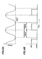
- Fig. 4A shows the waveform of the output voltage from the thermocouple 28 as seen at the input side of the A/D converter 47 after the amplification at the differential amplifier 41 and the noise elimination at the low-pass filter 46. Since the thermocouple 28 is exposed to the respiratory air passing the patient's nostril, its output voltage gradually increases during the exhalation phase in which the air is exhaled from the inside of the patient's body while its output gradually decreases during the inhalation phase. Thus, the output voltage of the thermocouple 28 is approximately sinusoidal.
- the A/D converter 47 converts the output of the thermocouple 28 into digital signals in the following manner.
- the CPU 49 samples the voltage of Fig. 4A at a regular interval of 10 msec in response to the interruption signal from the timer 50 and the sampled value is stored in the memory 51 as a temperature datum, and the CPU 49 compares the latest temperature as sampled against the preceding temperature datum retrieved from the memory 51. If the latest temperature as sampled is higher than the preceding temperature datum, the respiration is in the exhalation phase wherein the output voltage of the thermocouple 28 gradually increases as shown in Fig. 4A.
- a binary flag « 1 for exhalation and a binary flag «0» for inhalation are stored in the memory 52 during the respective phases.
- the memory 52 carries a binary flag « 1 indicating that the respiration is in the exhalation phase.
- the temperature datum stored in the memory 51 is renewed by the latest sampled temperature only when such latest temperature as sampled from the A/D converter 47 is higher than the preceding temperature datum retrieved from the memory 51. If the latest temperature as sampled is lower than the preceding temperature datum retrieved from the memory 51, i.e., at the transit from the exhalation phase to the inhalation phase, the binary flag in the memory 52 is changed to «0» and the latest lower temperature as sampled is stored in the memory 51 as a new datum.
- the breath-synchronizing solenoid valve 24 is turned on for opening the passage to the nasal cannula 26, and the supply of oxygen-enriched gas to the patient 22 starts while the buzzer 57 starts to sound. Thereafter, during the inhalation phase, as long as the newly sampled temperature is lower than the preceding temperature datum, such newly sampled temperature is stored in the memory 51 for renewing the temperature datum therein.
- Both the duration of the inhalation phase from the exhalation-inhalation transit to the inhalation-exhalation transit and the duration of the exhalation phase from the inhalation-exhalation transit to the exhalation-inhalation transit are measured by a combination of the CPU 49 and the timer 50. Whether each of the thus measured durations falls in a normal range or not is checked by a program stored in the memory 54. In the illustrated embodiment, the normal range of the duration of both the inhalation and exhalation phases is assumed to be 1-15 seconds. When durations of the inhalation and exhalation phases are normal, data on the immediately prededing six consecutive sound inhalation durations are stored in the memory 53 while renewing them in succession.
- any of the inhalation durations and exhalation durations falls outside the above normal range, it is assumed that abnormality of a kind has occurred on the side of the patient 22 or the thermocouple 28. Such abnormality is informed to doctors and nurses by actuating the alarm 56 by the CPU 49.
- the breath-synchronizing solenoid valve 24 is controlled in such a manner that the oxygen-enriched gas is continuously supplied to the patient 22.
- the renewal of the data on the preceding six consecutive sound inhalation durations is effected when a new inhalation duration datum of the latest sound respiratory cycle is made available by erasing the oldest (seven respiratory cycles before) datum and storing such new inhalation duration datum.
- the oxygen-enriched gas is supplied only in the inhalation phase.
- the duration of such supply namely, the duration of the opening of the breath-synchronizing solenoid valve 24 (to be referred to as the «valve open time») is controlled by a combination of a time ratio set on the outside input means 55 and the average of the preceding six consecutive sound inhalation durations. More particularly, at the transit from the exhalation phase to the inhalation phase, data on the immediately preceding six consecutive sound inhalation durations are read from the memory 53 for determining the average value thereof. A product of that average value of the inhalation durations and the rime ratio set on the outside input means 55 is calculated. The valve open time is determined by subtracting the above product from the above average value of the six inhalation durations.
- That valve open time is set on the timer 50, and as the oxygen-enriched gas is supplied it is counted down, so that when the thus set time is reduced to zero by the counting down the breath-synchronizing solenoid valve 24 is closed.
- the valve open time for the breath-synchronizing solenoid valve 24 for a specific inhalation phase is shorter than the average value of the immediately preceding six consecutive inhalation durations by the time ratio set on the outside input means 55, as shown in Fig. 4B.
- the gas to be filled in the trachea or other dead space of the patient 22 is provided by the atmospheric air inhaled by him during the time corresponding to the above time ration.
- the CPU detects the transit from the inhalation to exhalation based on the temperature data during the above counting down at the timer 50, and the flag in the memory 52 is changed from «0» to «1 Farm
- the breath-synchronizing solenoid valve 24 is closed before the valve open time is counted to zero at the timer 50.
- Fig. 5 shows a flow chart of the operation of the CPU 49 in response to the interruption signals from the timer 50 at 10 msec intervals.
- the operation of the CPU will be summarized now.
- the breath-synchronizing solenoid valve 24 is kept open at first unit six consecutive sound inhalation duration data are stored in the memory 53, so that the oxygen-enriched gas is continuously supplied to the patient's respiratory organ during such initial period.
- the valve open time for that inhalation phase is determined based on the average of the thus stored data in the memory 53 and the time ratio set on the outside input means 55, and the breath-synchronizing solenoid valve 24 is turned on from the start of that inhalation phase for the period of the thus determined valve open time so as to supply the oxygen-enriched gas to the respiratory organ of the patient 22 or the like living body.
- the inhalation duration data older than six respiratory cycles before the present instant are erased from the memory 53, so as to ensure the derivation of the average of the latest six consecutive sound inhalation durations.
- the breath-synchronizing solenoid valve 24 is immediately turned on so as to continuously supply the oxygen-enriched gas to the patient or the like, and atthe same time the alarm 56 is actuated.
- the breath-synchronized operation is resumed and the alarm 56 is turned off.
- the continuous supply of the oxygen-enriched gas is maintained and the alarm 56 is continuously actuated.
- the valve open time of the breath-synchronizing solenoid valve 24 is determined based on the preceding six consecutive inhalation durations.
- the invention is not restricted to such preceding six inhalation durations, and an average of an arbitrary number of the preceding inhalation durations can be used for determining the valve open time.
- the valve open time may be determined by taking a product of the duration of the immediately preceding inhalation phase and the time ratio set on the outside input means 55 and by subtracting such product from the duration of the immediately preceding inhalation phase.
- the valve open time for a following inhalation phase may be determined by taking the average of such a calculated time determined based on the immediately prededing inhalation duration and more preceding valve open times. That is, the valve open time for the next inhalation phase is determined by an average of the preceding valve open time and the present inhalation duration so measured minus a product of it and the ratio set on the outside input means.
- Fig. 6 shows another embodiment of the oxygen concentrator to be used in the concentrated-oxygen supplier of the invention.
- the oxygen concentrator 61 of this embodiment uses one compressor 6 which is alternately connected to two adsorption cylinders 3 and 4 through a five-way solenoid valve 62.
- the formation of the oxygen concentrator 61 is similar to that ofthe oxygen concentrator 1 of Fig. 1 exceptthe above five-way solenoid valve 62 and the use of only one compressor 6.
- Like parts are designated by like numerals.
- the five-way solenoid valve 62 has s liding valve 63 which can selectively assume a first position as shown in Fig. 6 and a second position to the left thereof.
- the valve 63 connects the compressor 6 to the adsorption cylinder 3 through a passage 64 while connecting the adsorption cylinder 4 to the silencer 16 through another passage 65.
- the valve 63 located at the second position connects the compressor 6 to the adsorption cylinder 4 through the passage 65 while connecting the adsorption cylinder 3 to the silencer 16 through the passage 64.
- a controller means 66 shifts the valve 63 between the first position and the second position in response to the output from the pressure switch 12. More particularly, when the compressor 6 operates with the valve 63 at the position 1 as shown in Fig. 6, the air cleansed by the air cleaner 5 and compressed by the compressor 6 enters the adsorption cylinder 3 through the passage 64, so as to produce oxygen-enriched gas. As in the case of Fig. 1, the thus produced oxygen-enriched gas is stored in the reservoir tank 2 through the one-way valve 9, and at the same time a part of the oxygen-enriched gas is delivered to the other adsorption cylinder 4 through the orifice 11 as purge gas. The purge gas causes desorption of nitrogen and moisture from the adsorbent in the adsorption cylinder 4, and the desorption products are discharged to the atmosphere together with the purge gas through the passage 65 and the silencer 16.
- the pressure switch 12 When the inside pressure of the adsorption cylinder 3 increases and reaches a certain predetermined value, the pressure switch 12 generates and transmits such a signal to the controller means 66 that the sliding valve 63 is shifted from the position 1 to the left as seen in Fig. 6 until reaching its second position. Whereby, the gas in the adsorption cylinder 3 is discharged to the atmosphere together with desorbed nitrogen and moisture through the passage 64 and the silencer 16. At the same time, the air cleansed by the air cleaner 5 and compressed 6 enters the adsorption cylinder 4 through the passage 65 for producing the oxygen-enriched gas.
- the thus produced oxygen-enriched gas is stored in the reservoir tank 2 through the one-way valve 10, while a part of the oxygen-enriched gas is delivered to the adsorption cylinder 3 through the orifice 11 as the purge gas for effecting the regeneration and reactivation of the adsorbent therein.
- the controller means 66 shifts the valve 63 of the five-way valve 62 to the first position as shown in Fig. 6. Whereby, the oxygen concentrator comes back to the initial condition and one cycle of the operation of the oxygen concentrator of Fig. 6 is completed.
- one compressor 6 can alternately pressurize and purge the two adsorption cylinders as in the case of Fig. 1 using two compressors.
- the oxygen concentrator to be used in the concentrated-oxygen supplier of the invention is not restricted to the above adsorption type, but membrane type oxygen concentrator can be also used in the present invention.
- the breath-synchronized concentrated-oxygen supplier of the invention uses a combination of an oxygen concentrator, a buffer tank, a breath-synchronizing solenoid valve, and a gas-supply regulator which limits the opening time of the above solenoid valve only to a period available for useful usage of the oxygen gas, so that the following outstanding effects can be achieved.
- the breath-synchronized type supply according to the invention which supplies the oxygen gas only during the inhalation phase, improves the performance and inhalation efficiency of the supplier to a great extent in comparison with the conventional continuous supply type. If breathing apparatuses of the breath-synchronized supply type and the continuous supply type are made to obtain the same inhalation efficiency by using the same oxygen concentrator, the breath-synchronized supply type can be made much smaller in size, lighter in weight, and more energy saving than the continuous supply type. Accordingly, the concentrated-oxygen supplier of the invention makes an epoch-making progress in the art and makes the oxygen inhalation treatment at home more readily available.
- Oxygen inhalation efficiency in the living body was tested with four models of inhalation; namely, a model (1) with inhalation of air, a model (2) with a continuous supply of oxygen-enriched gas at 2 P/min from an oxygen concentrator, a model (3) with a supply of oxygen-enriched gas at 2 P/min only for inhalation phases from an oxygen concentrator through a three-way valve which discharged the oxygen-enriched gas to the atmosphere during exhalation phases, and a model (4) with a supply of oxygen-enriched gas at 2 P/min only for inhalation phases from an oxygen concentrator through a two-way valve which stored the oxygen-enriched gas in a buffer tank during exhalation phases.
- Table 3 The result is shown in Table 3.
- oxygen inhalation efficiency in the living body was tested for different flow rates of inhaling oxygen gas under different gas supplying conditions; namely, condition (i) under continuous oxygen gas supply, condition (ii) under intermittent oxygen gas supply with a 100 mP buffer tank, condition (iii) under intermittent oxygen gas supply with a 200 mt buffer tank, and condition (iv) under intermittent oxygen gas supply with a 400 mP buffer tank.
- condition (i) under continuous oxygen gas supply condition (ii) under intermittent oxygen gas supply with a 100 mP buffer tank
- condition (iii) under intermittent oxygen gas supply with a 200 mt buffer tank condition (iv) under intermittent oxygen gas supply with a 400 mP buffer tank.
- the oxygen-enriched gas can be inhaled at a very high efficiency.
- the model (4) of Table 3 shows that the use of the buffer tank, the capacity of which as small as 100 mfis shown to be effective enough in Table 4, improves the effectiveness of the breath-synchronized concentrated-oxygen supply system to a greater extent.
- the invention facilitates further miniaturation, weight reduction and energy saving in the oxygen concentrator.
- the interruption of the supply of the oxygen-enriched gas during exhalation phases contributes to speeding up of the pressure buildup at the adsorption cylinders and quickening of the switching of the alternate operations of the adsorption cylinders.
- the effect of such quickened switching will be positively combined with the above-mentioned effect of the alternate operation of two adsorption cylinders in improving the performance of the oxygen concentrator.
Landscapes
- Health & Medical Sciences (AREA)
- Emergency Medicine (AREA)
- Pulmonology (AREA)
- Life Sciences & Earth Sciences (AREA)
- General Health & Medical Sciences (AREA)
- Biomedical Technology (AREA)
- Heart & Thoracic Surgery (AREA)
- Hematology (AREA)
- Engineering & Computer Science (AREA)
- Animal Behavior & Ethology (AREA)
- Anesthesiology (AREA)
- Public Health (AREA)
- Veterinary Medicine (AREA)
- Otolaryngology (AREA)
- Oxygen, Ozone, And Oxides In General (AREA)
- Separation Of Gases By Adsorption (AREA)
- Respiratory Apparatuses And Protective Means (AREA)
Claims (4)
Applications Claiming Priority (2)
| Application Number | Priority Date | Filing Date | Title |
|---|---|---|---|
| JP253495/84 | 1984-11-30 | ||
| JP59253495A JPS61131756A (ja) | 1984-11-30 | 1984-11-30 | 呼吸同調送気式濃縮酸素供給装置 |
Publications (2)
| Publication Number | Publication Date |
|---|---|
| EP0188071A1 EP0188071A1 (de) | 1986-07-23 |
| EP0188071B1 true EP0188071B1 (de) | 1988-08-03 |
Family
ID=17252168
Family Applications (1)
| Application Number | Title | Priority Date | Filing Date |
|---|---|---|---|
| EP85308311A Expired EP0188071B1 (de) | 1984-11-30 | 1985-11-14 | Atmungssynchronisiertes Gerät zur Zufuhr von konzentriertem Sauerstoff |
Country Status (5)
| Country | Link |
|---|---|
| US (1) | US4681099A (de) |
| EP (1) | EP0188071B1 (de) |
| JP (1) | JPS61131756A (de) |
| CA (1) | CA1262223A (de) |
| DE (1) | DE3564075D1 (de) |
Cited By (2)
| Publication number | Priority date | Publication date | Assignee | Title |
|---|---|---|---|---|
| DE4338813C1 (de) * | 1993-11-15 | 1995-02-23 | Metrax Gmbh | Beatmungsgerät |
| WO2005063323A1 (en) * | 2003-12-29 | 2005-07-14 | Resmed Ltd | Mechanical ventilation in the presence of sleep disordered breathing |
Families Citing this family (128)
| Publication number | Priority date | Publication date | Assignee | Title |
|---|---|---|---|---|
| DE3601714A1 (de) * | 1986-01-22 | 1987-07-23 | Draegerwerk Ag | Vorrichtung zur anreicherung von atemgas mit sauerstoff |
| US4706664A (en) * | 1986-04-11 | 1987-11-17 | Puritan-Bennett Corporation | Inspiration oxygen saver |
| US4932402A (en) * | 1986-04-11 | 1990-06-12 | Puritan-Bennett Corporation | Inspiration oxygen saver |
| CA1297298C (en) * | 1986-09-22 | 1992-03-17 | Akira Kato | Oxygen enriching apparatus with means for regulating oxygen concentration of oxygen enriched gas |
| US4784130A (en) * | 1986-12-04 | 1988-11-15 | The John Bunn Company | Flow controller |
| US4826510A (en) * | 1988-01-13 | 1989-05-02 | The John Bunn Company | Portable low profile DC oxygen concentrator |
| US4813979A (en) * | 1988-02-02 | 1989-03-21 | The United States Of America As Represented By The Secretary Of The Air Force | Secondary oxygen purifier for molecular sieve oxygen concentrator |
| DE3817985A1 (de) * | 1988-05-27 | 1989-12-07 | Salvia Werk Gmbh | Geraet zur unterstuetzung der spontanen atmung eines patienten |
| US5048515A (en) * | 1988-11-15 | 1991-09-17 | Sanso David W | Respiratory gas supply apparatus and method |
| JPH02186506A (ja) * | 1989-01-13 | 1990-07-20 | Kurimoto Ltd | 導電性複合体およびその製造方法 |
| US4965989A (en) * | 1989-04-10 | 1990-10-30 | Lamar Ellis | In-line molecular sieve bed conversion kit |
| JP2502812Y2 (ja) * | 1989-07-21 | 1996-06-26 | 山陽電子工業株式会社 | デマンドバルブ制御におけるガス流量切替装置 |
| US5071453A (en) * | 1989-09-28 | 1991-12-10 | Litton Systems, Inc. | Oxygen concentrator with pressure booster and oxygen concentration monitoring |
| US4971609A (en) * | 1990-02-05 | 1990-11-20 | Pawlos Robert A | Portable oxygen concentrator |
| GB9125467D0 (en) * | 1991-11-29 | 1992-01-29 | Mockridge Jeffrey N A | Neo-natal ventilation apparatus |
| US5226933A (en) * | 1992-03-31 | 1993-07-13 | Ohio State University | Pressure swing adsorption system to purify oxygen |
| EP0569241B1 (de) | 1992-05-07 | 1999-12-22 | William A. Cook Australia Pty. Ltd. | Vorrichtung zur Insufflation mit Gas |
| FR2693910B1 (fr) * | 1992-07-23 | 1994-08-26 | Taema | Equipement et procédé de fourniture de doses d'au moins un gaz aux voies respiratoires d'un utilisateur. |
| CA2109017A1 (en) * | 1992-12-16 | 1994-06-17 | Donald M. Smith | Method and apparatus for the intermittent delivery of oxygen therapy to a person |
| US5438980A (en) * | 1993-01-12 | 1995-08-08 | Puritan-Bennett Corporation | Inhalation/exhalation respiratory phase detection circuit |
| US5546935A (en) * | 1993-03-09 | 1996-08-20 | Medamicus, Inc. | Endotracheal tube mounted pressure transducer |
| GB9320978D0 (en) * | 1993-10-12 | 1993-12-01 | Higenbottam Timohy W | Nitric oxide treatment |
| US5477861A (en) * | 1994-01-07 | 1995-12-26 | The United States Of America As Represented By The Secretary Of The Army | Respiratory test circuits and methods |
| FR2725137B1 (fr) * | 1994-09-29 | 1997-01-10 | Taema | Dispositif de detection de cycles respiratoires, notamment pour controler l'execution d'un traitement |
| AU701970B2 (en) * | 1994-10-25 | 1999-02-11 | Teijin Limited | An apparatus for supplying a respiratory gas to a patient |
| FR2727023B1 (fr) * | 1994-11-23 | 1996-12-27 | Taema | Appareil d'aide a la respiration |
| US5495848A (en) * | 1994-11-25 | 1996-03-05 | Nellcar Puritan Bennett | Monitoring system for delivery of therapeutic gas |
| US5531807A (en) * | 1994-11-30 | 1996-07-02 | Airsep Corporation | Apparatus and method for supplying oxygen to passengers on board aircraft |
| US5697364A (en) * | 1995-06-07 | 1997-12-16 | Salter Labs | Intermittent gas-insufflation apparatus |
| US5626131A (en) * | 1995-06-07 | 1997-05-06 | Salter Labs | Method for intermittent gas-insufflation |
| US5735268A (en) * | 1995-06-07 | 1998-04-07 | Salter Labs | Intermitten gas-insufflation apparatus and method therefor |
| EP0858353A4 (de) * | 1995-10-19 | 1999-12-01 | Invacare Corp | Sauerstoff konservierende vorrichtung |
| AU2565797A (en) * | 1996-02-23 | 1997-09-10 | Christoph Schuster | Oxygen inhaler |
| US6152134A (en) * | 1996-10-18 | 2000-11-28 | Invacare Corporation | Oxygen conserving device |
| US5865174A (en) * | 1996-10-29 | 1999-02-02 | The Scott Fetzer Company | Supplemental oxygen delivery apparatus and method |
| US5890490A (en) * | 1996-11-29 | 1999-04-06 | Aylsworth; Alonzo C. | Therapeutic gas flow monitoring system |
| DE19707097C2 (de) | 1997-02-22 | 1999-08-05 | Air Be C Medizintech Gmbh | Kombiniertes Sauerstofferzeugungs- und Sauerstoffversorgungssystem |
| US5915379A (en) | 1997-03-14 | 1999-06-29 | Nellcor Puritan Bennett Incorporated | Graphic user interface for a patient ventilator |
| CA2225013C (en) | 1997-04-04 | 2006-06-06 | Institut Du N.O. Inc. | Injection system for delivery of a gaseous substance |
| US5911219A (en) * | 1997-04-18 | 1999-06-15 | Aylsworth; Alonzo C. | Therapeutic gas flow meter and monitor |
| CA2617553C (en) * | 1997-06-17 | 2011-12-13 | Fisher & Paykel Healthcare Limited | Respiratory humidification system |
| US20040221844A1 (en) * | 1997-06-17 | 2004-11-11 | Hunt Peter John | Humidity controller |
| US10130787B2 (en) | 1997-06-17 | 2018-11-20 | Fisher & Paykel Healthcare Limited | Humidity controller |
| US6532958B1 (en) | 1997-07-25 | 2003-03-18 | Minnesota Innovative Technologies & Instruments Corporation | Automated control and conservation of supplemental respiratory oxygen |
| US6371114B1 (en) * | 1998-07-24 | 2002-04-16 | Minnesota Innovative Technologies & Instruments Corporation | Control device for supplying supplemental respiratory oxygen |
| US5881725A (en) * | 1997-08-19 | 1999-03-16 | Victor Equipment Company | Pneumatic oxygen conserver |
| SE9703290D0 (sv) * | 1997-09-11 | 1997-09-11 | Siemens Elema Ab | Ventilator |
| KR19990028153A (ko) * | 1997-09-30 | 1999-04-15 | 정휘동 | 포터블 피에스에이 산소발생기 |
| US6196222B1 (en) * | 1998-03-10 | 2001-03-06 | Instrumentarium Corporation | Tracheal gas insufflation delivery system for respiration equipment |
| DE19921917A1 (de) * | 1999-05-12 | 2000-12-14 | Michael Lerch | Verfahren und Vorrichtung zur Veränderung der standardatmosphärischen Zusammensetzung der Atemluft mit Gasen oder Gasgemischen |
| US6672300B1 (en) * | 1999-06-23 | 2004-01-06 | Graham Cameron Grant | Respiration assistor |
| AU757022B2 (en) * | 1999-06-23 | 2003-01-30 | Graham Cameron Grant | Respiration assistor |
| US6192883B1 (en) * | 1999-08-03 | 2001-02-27 | Richard L. Miller, Jr. | Oxygen flow control system and method |
| JP4293581B2 (ja) * | 2000-09-21 | 2009-07-08 | 日本特殊陶業株式会社 | 酸素濃縮器及び制御装置並びに記録媒体 |
| JP4246365B2 (ja) * | 2000-09-21 | 2009-04-02 | 日本特殊陶業株式会社 | 酸素濃縮器及びその制御装置並びに記録媒体 |
| JP2002085568A (ja) * | 2000-09-21 | 2002-03-26 | Ngk Spark Plug Co Ltd | 酸素供給装置及びその制御装置並びに記録媒体 |
| US6364161B1 (en) | 2000-09-27 | 2002-04-02 | Victor Equipment Company | Oxygen conserver |
| US6668828B1 (en) | 2000-10-16 | 2003-12-30 | Pulmonox Technologies Corporations | System and elements for managing therapeutic gas administration to a spontaneously breathing non-ventilated patient |
| US20050004511A1 (en) * | 2000-10-16 | 2005-01-06 | Curtis Figley | Method for purging a system for use in administrating therapeutic gas to a patient |
| US6622726B1 (en) | 2000-10-17 | 2003-09-23 | Newport Medical Instruments, Inc. | Breathing apparatus and method |
| US7096865B1 (en) * | 2000-10-18 | 2006-08-29 | Oxygen Lifeline, Llc | Personal gas supply delivery system |
| US6551384B1 (en) * | 2001-07-05 | 2003-04-22 | Praxair Technology, Inc. | Medical oxygen concentrator |
| WO2003037786A1 (fr) * | 2001-10-30 | 2003-05-08 | Teijin Limited | Dispositif d'enrichissement en oxygene |
| WO2003064009A1 (en) * | 2002-01-31 | 2003-08-07 | Airsep Corporation | Portable oxygen concentrator |
| US6669758B1 (en) * | 2002-06-27 | 2003-12-30 | Carleton Life Support Systems, Inc. | Variable inlet air restriction for composition control of product gas |
| US7320321B2 (en) * | 2002-08-26 | 2008-01-22 | Automedx Inc. | Self-contained micromechanical ventilator |
| US7080646B2 (en) * | 2002-08-26 | 2006-07-25 | Sekos, Inc. | Self-contained micromechanical ventilator |
| US6740146B2 (en) * | 2002-09-12 | 2004-05-25 | Edward L. Simonds | Oxygen concentrator |
| JP4598357B2 (ja) | 2002-12-17 | 2010-12-15 | 帝人株式会社 | 酸素供給装置 |
| US7073500B2 (en) * | 2003-05-23 | 2006-07-11 | Lawrence Kates | Method and apparatus for defending against naso-pharyngeal viral attacks |
| ES2655053T3 (es) | 2003-08-26 | 2018-02-16 | Teijin Pharma Limited | Aparato de suministro de gas |
| CN100584403C (zh) * | 2003-10-06 | 2010-01-27 | 多孔介质公司 | 氧气加湿器 |
| JP2007508052A (ja) | 2003-10-07 | 2007-04-05 | アイノゲン、インコーポレイテッド | 携帯型ガス分離システム |
| US20050072426A1 (en) * | 2003-10-07 | 2005-04-07 | Deane Geoffrey Frank | Portable gas fractionalization system |
| US7135059B2 (en) * | 2003-10-07 | 2006-11-14 | Inogen, Inc. | Portable gas fractionalization system |
| US20050072423A1 (en) * | 2003-10-07 | 2005-04-07 | Deane Geoffrey Frank | Portable gas fractionalization system |
| US7066985B2 (en) * | 2003-10-07 | 2006-06-27 | Inogen, Inc. | Portable gas fractionalization system |
| US7617826B1 (en) | 2004-02-26 | 2009-11-17 | Ameriflo, Inc. | Conserver |
| US8146592B2 (en) * | 2004-02-26 | 2012-04-03 | Ameriflo, Inc. | Method and apparatus for regulating fluid flow or conserving fluid flow |
| US7025329B2 (en) * | 2004-04-30 | 2006-04-11 | Sequal Technologies, Inc. | Needle valve for flow control |
| US7954490B2 (en) | 2005-02-09 | 2011-06-07 | Vbox, Incorporated | Method of providing ambulatory oxygen |
| US7368005B2 (en) * | 2005-04-05 | 2008-05-06 | Respironics Oxytec, Inc. | Portable oxygen concentrator |
| US7402193B2 (en) * | 2005-04-05 | 2008-07-22 | Respironics Oxytec, Inc. | Portable oxygen concentrator |
| US7329304B2 (en) * | 2005-04-05 | 2008-02-12 | Respironics Oxytec, Inc. | Portable oxygen concentrator |
| JP4644517B2 (ja) | 2005-04-19 | 2011-03-02 | 伸和コントロールズ株式会社 | 4ポート自動切換えバルブ |
| US7585166B2 (en) * | 2005-05-02 | 2009-09-08 | Buja Frederick J | System for monitoring temperature and pressure during a molding process |
| US7686870B1 (en) | 2005-12-29 | 2010-03-30 | Inogen, Inc. | Expandable product rate portable gas fractionalization system |
| US8790256B2 (en) * | 2006-08-14 | 2014-07-29 | Frederick J. Buja | System and method employing a thermocouple junction for monitoring of physiological parameters |
| US20080110462A1 (en) * | 2006-11-10 | 2008-05-15 | Chekal Michael P | Oxygen delivery system |
| US9586018B2 (en) | 2007-01-26 | 2017-03-07 | Cs Medical, Inc. | System for providing flow-targeted ventilation synchronized to a patients breathing cycle |
| US8020558B2 (en) | 2007-01-26 | 2011-09-20 | Cs Medical, Inc. | System for providing flow-targeted ventilation synchronized to a patient's breathing cycle |
| US9557057B2 (en) | 2007-02-09 | 2017-01-31 | Dale Robert Lutz | Reliable carbon-neutral power generation system |
| CN101605871B (zh) | 2007-02-09 | 2015-03-25 | 戴尔·R·鲁兹 | 可靠的碳-中性发电系统 |
| US20080230062A1 (en) * | 2007-03-23 | 2008-09-25 | General Electric Company | Setting expiratory time in mandatory mechanical ventilation based on a deviation from a stable condition of exhaled gas volumes |
| US20090065007A1 (en) * | 2007-09-06 | 2009-03-12 | Wilkinson William R | Oxygen concentrator apparatus and method |
| US8267081B2 (en) | 2009-02-20 | 2012-09-18 | Baxter International Inc. | Inhaled anesthetic agent therapy and delivery system |
| US8394178B2 (en) | 2009-07-22 | 2013-03-12 | Vbox, Incorporated | Apparatus for separating oxygen from ambient air |
| JP5517332B2 (ja) * | 2009-08-28 | 2014-06-11 | アルバック機工株式会社 | 人工呼吸器及びその作動方法 |
| EP2498849B1 (de) * | 2009-11-11 | 2022-08-10 | The Board of Trustees of the Leland Stanford Junior University | Tragbare beatmungsvorrichtung |
| JP5495766B2 (ja) * | 2009-12-18 | 2014-05-21 | 株式会社医器研 | 酸素濃縮装置 |
| KR20110076542A (ko) * | 2009-12-29 | 2011-07-06 | 서강대학교산학협력단 | 고효율 기체 농축 장치 및 그 제어방법 |
| US8986205B2 (en) | 2010-05-14 | 2015-03-24 | Frederick J. Buja | Sensor for measurement of temperature and pressure for a cyclic process |
| US8616207B2 (en) | 2010-09-07 | 2013-12-31 | Inova Labs, Inc. | Oxygen concentrator heat management system and method |
| US20120055474A1 (en) | 2010-09-07 | 2012-03-08 | Wilkinson William R | Methods and systems for providing oxygen enriched gas |
| US10583265B2 (en) | 2011-09-13 | 2020-03-10 | Koninklijke Philips N.V. | Proportional oxygen conserving device with flow sensing |
| US10751500B2 (en) * | 2011-11-30 | 2020-08-25 | Oxus Co., Ltd. | Apparatus and method for oxygen delivery |
| CN102500025B (zh) * | 2011-12-01 | 2014-04-09 | 于邦仲 | 一种呼吸机防窒息自由吸气系统 |
| NZ707260A (en) * | 2012-10-12 | 2017-12-22 | Inova Labs Inc | Oxygen concentrator systems and methods |
| AU2013328915B2 (en) | 2012-10-12 | 2018-04-26 | Inova Labs, Inc. | Dual oxygen concentrator systems and methods |
| WO2014059405A1 (en) | 2012-10-12 | 2014-04-17 | Inova Labs, Inc. | Method and systems for the delivery of oxygen enriched gas |
| US9440179B2 (en) | 2014-02-14 | 2016-09-13 | InovaLabs, LLC | Oxygen concentrator pump systems and methods |
| US10758703B2 (en) | 2014-10-17 | 2020-09-01 | Mallinckrodt Hospital Products IP Limited | Systems and methods for providing a pulse of a therapeutic gas with a desired flow profile to maximize therapeutic effectiveness |
| CN104287921A (zh) * | 2014-10-30 | 2015-01-21 | 王有存 | 高压氧舱供排氧系统 |
| US10245406B2 (en) | 2015-03-24 | 2019-04-02 | Ventec Life Systems, Inc. | Ventilator with integrated oxygen production |
| US11247015B2 (en) | 2015-03-24 | 2022-02-15 | Ventec Life Systems, Inc. | Ventilator with integrated oxygen production |
| US11458274B2 (en) | 2016-05-03 | 2022-10-04 | Inova Labs, Inc. | Method and systems for the delivery of oxygen enriched gas |
| US10773049B2 (en) | 2016-06-21 | 2020-09-15 | Ventec Life Systems, Inc. | Cough-assist systems with humidifier bypass |
| US10894139B2 (en) * | 2018-01-19 | 2021-01-19 | Ergo-Flex Technologies, LLC | Oxygen treatment device for mammals |
| JP2021524795A (ja) | 2018-05-13 | 2021-09-16 | サミール・サレハ・アフマド | ポータブル酸素濃縮器を使用するポータブル医療用人工呼吸器システム |
| CN111694382B (zh) * | 2019-03-15 | 2024-06-25 | 欧姆龙健康医疗(中国)有限公司 | 供气浓度调节方法、供气浓度调节系统和制氧机 |
| WO2021016482A1 (en) * | 2019-07-24 | 2021-01-28 | Bunnell Incorporated | Pulmonary ventilator with changeable filters |
| WO2021211084A1 (ru) * | 2020-04-14 | 2021-10-21 | Роман Степанович КАДЕЛЯК | Установка для обогащения воздуха кислородом |
| US20220040426A1 (en) * | 2020-08-05 | 2022-02-10 | Effortless Oxygen, Llc | Flow Triggered Gas Delivery |
| CN116157182A (zh) * | 2020-08-05 | 2023-05-23 | 轻松氧气有限责任公司 | 流量触发的气体输送 |
| US11247008B1 (en) * | 2020-08-05 | 2022-02-15 | Effortless Oxygen, Llc | Flow triggered gas delivery |
| US11318276B2 (en) | 2020-08-05 | 2022-05-03 | Effortless Oxygen, Llc | Flow triggered gas delivery |
| US11420007B2 (en) | 2020-08-05 | 2022-08-23 | Effortless Oxygen, Llc | Flow triggered gas delivery |
| CN113648525B (zh) * | 2021-07-26 | 2023-05-05 | 河北医科大学第二医院 | 一种重症监护室防细菌感染装置 |
Family Cites Families (15)
| Publication number | Priority date | Publication date | Assignee | Title |
|---|---|---|---|---|
| US3357428A (en) * | 1963-12-23 | 1967-12-12 | David L Carlson | Respiratory augmentor with electronic monitor and control |
| CH568756A5 (de) * | 1973-09-07 | 1975-11-14 | Hoffmann La Roche | |
| US3880616A (en) * | 1973-11-19 | 1975-04-29 | Bendix Corp | Respiratory support system |
| US4106503A (en) * | 1977-03-11 | 1978-08-15 | Richard R. Rosenthal | Metering system for stimulating bronchial spasm |
| GB1583273A (en) * | 1977-05-06 | 1981-01-21 | Medishield Corp Ltd | Lung ventilators |
| SE409175B (sv) * | 1977-11-29 | 1979-08-06 | Aga Ab | Anordning vid en respirator for metning av till en patient tillford gasmengd |
| JPS55149620A (en) * | 1979-05-11 | 1980-11-21 | Noboru Sato | Oxygen-enriching system having good rise-up characteristic |
| DE2926747C2 (de) * | 1979-07-03 | 1982-05-19 | Drägerwerk AG, 2400 Lübeck | Beatmungsanlage mit von Patientenwerten gesteuertem Beatmungsgerät |
| FR2483785A1 (fr) * | 1980-06-10 | 1981-12-11 | Air Liquide | Respirateur a correction automatique de ventilation |
| US4484578A (en) * | 1980-11-26 | 1984-11-27 | Kircaldie, Randall And Mcnab | Respirator apparatus and method |
| JPS598972A (ja) * | 1982-07-07 | 1984-01-18 | 佐藤 暢 | 開放型呼吸システムにおける呼吸同調式ガス供給制御方法および装置 |
| US4506666A (en) * | 1982-12-03 | 1985-03-26 | Kircaldie, Randall And Mcnab | Method and apparatus for rectifying obstructive apnea |
| US4534346A (en) * | 1983-03-15 | 1985-08-13 | Guild Associates, Inc. | Pressure swing cycle for the separation of oxygen from air |
| US4584996A (en) * | 1984-03-12 | 1986-04-29 | Blum Alvin S | Apparatus for conservative supplemental oxygen therapy |
| US4612928A (en) * | 1984-08-28 | 1986-09-23 | Tiep Brian L | Method and apparatus for supplying a gas to a body |
-
1984
- 1984-11-30 JP JP59253495A patent/JPS61131756A/ja active Granted
-
1985
- 1985-11-13 US US06/797,654 patent/US4681099A/en not_active Expired - Lifetime
- 1985-11-14 EP EP85308311A patent/EP0188071B1/de not_active Expired
- 1985-11-14 DE DE8585308311T patent/DE3564075D1/de not_active Expired
- 1985-11-20 CA CA000495799A patent/CA1262223A/en not_active Expired
Cited By (2)
| Publication number | Priority date | Publication date | Assignee | Title |
|---|---|---|---|---|
| DE4338813C1 (de) * | 1993-11-15 | 1995-02-23 | Metrax Gmbh | Beatmungsgerät |
| WO2005063323A1 (en) * | 2003-12-29 | 2005-07-14 | Resmed Ltd | Mechanical ventilation in the presence of sleep disordered breathing |
Also Published As
| Publication number | Publication date |
|---|---|
| DE3564075D1 (en) | 1988-09-08 |
| US4681099A (en) | 1987-07-21 |
| JPS61131756A (ja) | 1986-06-19 |
| JPS6237996B2 (de) | 1987-08-14 |
| EP0188071A1 (de) | 1986-07-23 |
| CA1262223A (en) | 1989-10-10 |
Similar Documents
| Publication | Publication Date | Title |
|---|---|---|
| EP0188071B1 (de) | Atmungssynchronisiertes Gerät zur Zufuhr von konzentriertem Sauerstoff | |
| US4648395A (en) | Synchronized feed type oxygen concentrator for use in an open breathing system | |
| US4584996A (en) | Apparatus for conservative supplemental oxygen therapy | |
| US4686974A (en) | Breath synchronized gas-insufflation device and method therefor | |
| JP3366651B2 (ja) | 呼気内の一酸化窒素の特定装置 | |
| JP4796918B2 (ja) | 酸素濃縮ガス供給装置 | |
| JP4293581B2 (ja) | 酸素濃縮器及び制御装置並びに記録媒体 | |
| JP2002085568A (ja) | 酸素供給装置及びその制御装置並びに記録媒体 | |
| JP2002085567A (ja) | 酸素濃縮器及びその制御装置並びに記録媒体 | |
| DE699084T1 (de) | Mess- und regelgerät für die atemtherapie | |
| US20110108033A1 (en) | Apparatus and method for controlled delivery of a breathing gas to the respiratory tracts of a user | |
| CN106922130A (zh) | 用于递送药剂的正压吸气装置 | |
| JPH10179742A (ja) | 携帯用一酸化窒素−酸素ガス供給装置およびその操作方法 | |
| KR101725877B1 (ko) | 의료용 고압 산소 챔버 내부의 이산화탄소 배출시스템 및 이를 이용한 이산화탄소 배출방법 | |
| JP3531215B2 (ja) | 医療用酸素ガス供給装置 | |
| WO2024131144A1 (zh) | 一种呼吸机控制方法及呼吸机 | |
| JPH0565200B2 (de) | ||
| CN110860019A (zh) | 一种智能控制的多功能医用制氧机 | |
| CN116157182A (zh) | 流量触发的气体输送 | |
| JP2000037458A (ja) | 医療用酸素濃縮器 | |
| JPH01221170A (ja) | 呼吸用気体供給装置 | |
| JPH08187289A (ja) | 呼吸用気体供給装置 | |
| JPH0363907B2 (de) | ||
| JP4606655B2 (ja) | 呼吸用気体供給装置 | |
| RU2745983C1 (ru) | Устройство принудительной вентиляции дыхательной системы с удалением избыточной влаги |
Legal Events
| Date | Code | Title | Description |
|---|---|---|---|
| PUAI | Public reference made under article 153(3) epc to a published international application that has entered the european phase |
Free format text: ORIGINAL CODE: 0009012 |
|
| AK | Designated contracting states |
Kind code of ref document: A1 Designated state(s): DE GB |
|
| 17P | Request for examination filed |
Effective date: 19860819 |
|
| 17Q | First examination report despatched |
Effective date: 19871028 |
|
| GRAA | (expected) grant |
Free format text: ORIGINAL CODE: 0009210 |
|
| AK | Designated contracting states |
Kind code of ref document: B1 Designated state(s): DE GB |
|
| REF | Corresponds to: |
Ref document number: 3564075 Country of ref document: DE Date of ref document: 19880908 |
|
| PLBI | Opposition filed |
Free format text: ORIGINAL CODE: 0009260 |
|
| 26 | Opposition filed |
Opponent name: DRAEGERWERK AG Effective date: 19890412 |
|
| PLBM | Termination of opposition procedure: date of legal effect published |
Free format text: ORIGINAL CODE: 0009276 |
|
| STAA | Information on the status of an ep patent application or granted ep patent |
Free format text: STATUS: OPPOSITION PROCEDURE CLOSED |
|
| 27C | Opposition proceedings terminated |
Effective date: 19891105 |
|
| REG | Reference to a national code |
Ref country code: GB Ref legal event code: IF02 |
|
| PGFP | Annual fee paid to national office [announced via postgrant information from national office to epo] |
Ref country code: GB Payment date: 20041110 Year of fee payment: 20 |
|
| PGFP | Annual fee paid to national office [announced via postgrant information from national office to epo] |
Ref country code: DE Payment date: 20041230 Year of fee payment: 20 |
|
| PG25 | Lapsed in a contracting state [announced via postgrant information from national office to epo] |
Ref country code: GB Free format text: LAPSE BECAUSE OF EXPIRATION OF PROTECTION Effective date: 20051113 |
|
| REG | Reference to a national code |
Ref country code: GB Ref legal event code: PE20 |