EP0187392A1 - Verfahren und Vorrichtung zur Bestimmung des Frischegrades von Fischen oder anderen Fleischstücken - Google Patents
Verfahren und Vorrichtung zur Bestimmung des Frischegrades von Fischen oder anderen Fleischstücken Download PDFInfo
- Publication number
- EP0187392A1 EP0187392A1 EP85116669A EP85116669A EP0187392A1 EP 0187392 A1 EP0187392 A1 EP 0187392A1 EP 85116669 A EP85116669 A EP 85116669A EP 85116669 A EP85116669 A EP 85116669A EP 0187392 A1 EP0187392 A1 EP 0187392A1
- Authority
- EP
- European Patent Office
- Prior art keywords
- food
- electrodes
- pieces
- freshness
- measuring
- Prior art date
- Legal status (The legal status is an assumption and is not a legal conclusion. Google has not performed a legal analysis and makes no representation as to the accuracy of the status listed.)
- Withdrawn
Links
Images


Classifications
-
- G—PHYSICS
- G01—MEASURING; TESTING
- G01N—INVESTIGATING OR ANALYSING MATERIALS BY DETERMINING THEIR CHEMICAL OR PHYSICAL PROPERTIES
- G01N27/00—Investigating or analysing materials by the use of electric, electrochemical, or magnetic means
- G01N27/02—Investigating or analysing materials by the use of electric, electrochemical, or magnetic means by investigating impedance
-
- G—PHYSICS
- G01—MEASURING; TESTING
- G01N—INVESTIGATING OR ANALYSING MATERIALS BY DETERMINING THEIR CHEMICAL OR PHYSICAL PROPERTIES
- G01N33/00—Investigating or analysing materials by specific methods not covered by groups G01N1/00 - G01N31/00
- G01N33/02—Food
- G01N33/12—Meat; fish
Definitions
- the present Invention relates to a method of determining the degree of freshness of pieces of food such as fish, fillets of fish with or without skin, and other kinds of meat.
- This known apparatus is intended for measurement of randomly selected test samples, the apparatus comprising an abutment surface having electrical electrodes embedded therein.
- the freshness of a fish is measured by contacting the abutment surface of the apparatus with one side of the fish, and the result of the measurement may then be read from a digital display or another kind of display unit.
- Tests have shown that the measuring results obtained by means of this known apparatus are substantially independent of the position at which the measurement is carried out provided that the abutment surface of the apparatus is placed adjacent to the median line of the fish and not too close to the head or tail of the fish. It is therefore proposed to use the known apparatus for making a single measurement for each fish at a closely defined position adjacent to the median line of the fish.
- the present invention provides a method of the above type permitting a quick and accurate electrical measurement of rather large quantities of fish or other pieces of food so that the measurements made may in practice be used as a basis for sorting the fish or pieces of food.
- the method according to the invention is of the type, wherein a set of electrodes are brought Into contact with each piece of food for determining the degree of freshness of said piece by means of the- electrodes, and the method is characterized In that the pieces of food are successively moved along a path of movement past said first set of electrodes while one side of each piece of food is kept in contact with the electrodes, and in that a plurality of successive electrical measurements are carried out by means of the electrodes on each piece of food passing the electrodes.
- the path of movement along which the pieces of food or the fish are moved and in which the said electrodes are arranged may, for example, be a path for transporting the pieces of food from one processing station or processing apparatus (such as sorting, cleaning, cutting, salting), or the path of movement may constitute part of such processing apparatus.
- a rather high number of measurements are made while each piece of food or each fish is passing the set of electrodes, and the measuring signals generated may be transmitted to an electronic calculating or control device or unit such as a microcomputer, which may be programmed so as to register the measurements of freshness for each single piece of food and possibly for sorting the pieces of food on the basis of these measuring results, for example by diverting pieces of food which are judged to be not sufficiently fresh, from the path of movement.
- the degree of freshness of a piece of food may vary from one area to another of the same piece of food. This may, for example, be true for fish which have been stored without being sufficiently covered by ice so that some areas of a fish are covered by ice while other areas of the same fish have been uncovered and possibly exposed to the sun.
- the electronic control unit may be programmed so as to discard a piece of food if one or any other predetermined maximum number of the measurements made on this piece of food does not correspond to a predetermined degree of freshness.
- the degree of freshness of each single piece of food is determined by averaging the plurality of values of measurements obtained.
- the measurements carried out at the rim zones are normally disregarded.
- the degree of freshness of a piece of food may vary from one area to another on the same side of the piece of food, but the degree of freshness may vary to an even higher degree from one side of the piece of food to the other.
- the pieces of food are fish which have been stored without being sufficiently covered by ice
- the upper side of a fish may be uncovered and possibly exposed to the sun, while the lower side may be supported on a layer of Ice.
- each piece of food, which has been moved past the set of electrodes may be turned upside down and moved past and brought into contact with a second set of electrodes for measuring the degree of freshness of the other side of this piece of food.
- the electronic control device or unit may then be programmed so as to also register the measuring results from this other side of the piece of food and possibly for discarding such pieces of food if the degree of freshness of the said other side thereof is not found to be satisfactory.
- the pieces of food for which the freshness is being determined are moved over a weighing device or weighing unit positioned in the path of movement and the pieces of food may then be sorted on the basis of their degree of freshness as well as their weight.
- the pieces of food may be divided into groups each comprising pieces of food having a weight within predetermined limits, and the pieces of food having a degree of freshness which does not fulfill predetermined criteria may be routed to a special group irrespective of their weight. It should be understood that the sorting may be based not only on the degree of freshness, but also on other criteria, such as length or shape, if desired.
- the type of the set of electrodes used may be chosen dependent on the type of food in question.
- the set of electrodes may comprise a pH-meter when the pieces of food are meat from mammals.
- the said pieces of food are fish or fillets of fish with skin it is preferred to base the determination of the degree of freshness on measurements of the electrical impedance of part of the piece of food in question by means of electrodes or on measurements of one or more other measuring values, such as the phase angle, the resistance, the reactance, the sharpness of resonance, the time constant, etc., related to the electrical impedance, or combinations of such measuring values.
- the measurement of the electrical impedance or the measurement of the measuring value(s) related thereto may be carried out by comparing a voltage or current supplied to an area of the piece of food with the response provided in the form of a current or voltage response for determining the electrical impedance or the measuring values in question in accordance with well-known physical principles including Ohm's law, etc.
- Dependent on the measuring values to be determined and dependent on whether it is desired to cause polarisatlon of the electrodes in contact with the said area of the piece of food in question, alternating or constant voltages or currents or combinations of alternating and constant voltages and currents may be used.
- the determination of the degree of freshness of each piece of food is carried out by means of four electrodes, a first pair of which is used as emitter electrodes, and a second pair of which is used as receiver electrodes, by supplying an alternating current to said pair of emitter electrodes, by measuring the alternating voltage generated over the receiver electrodes, and by measuring the phase angle between the current supplied and the voltage generated.
- the invention also relates to an apparatus for determining the degree of freshness of pieces of food, such as fish and other kinds of meat, said apparatus comprising a supporting surface, moving means for successively moving the pieces of food along a path of movement defined by said supporting surface, measuring means positioned along the path of movement for measuring characteristics of the pieces of food, and sorting means for sorting the pieces -of food on the basis of the measurements carried out by the measuring means, and the apparatus according to the invention is characterized in that the measuring means comprises a set of electrodes positioned at the supporting surface along the path of movement and adapted to determine the degree of freshness of the pieces of food.
- Such apparatus may be used for sorting pieces of food on the basis of their degree of freshness and possibly also on the basis of one or more other measurable characteristics, such as weight, length, shape, colour, type, etc. as explained above.
- the measuring means of the apparatus preferably further comprise a further set of electrodes for determining the degree of freshness of the pieces of food and positioned at the supporting surface along the path of movement and turning means for turning upside-down passing pieces of food, the turning means being arranged between the two sets of electrodes.
- the path of movement may e.g. comprise a pair of aligned path lengths
- the turning means may e.g. comprise a pivotally mounted turning flap or a turning wheel.
- the supporting surface may comprise vertically spaced upper and lower substantially horizontally extending surface parts
- the moving means may comprise an endless conveyor belt, which is provided with carriers and has its upper and lower paths extending along said upper and lower surface parts, respectively.
- the total length of the apparatus may be made smaller than the total length of a corresponding apparatus in which the path of movement comprises two aligned path lengths.
- the pieces of food may be turned upside down by the conveyor belt when they pass from one of the vertically spaced surface parts to the other. This means that the use of a turning flap, a turning wheel or another special device for turning the pieces of food is unnecessary.
- the sorting of the pieces of food may be carried out not only on the basis of their degree of freshness, but also on the basis of one or more further criteria, such as the weight, length, shape, colour and/or the type of the pieces of food.
- fish are sorted with regard to their size on the basis of their weight.
- the measuring means may further comprise a weighing device or a weighing unit, and diverting means, which may e.g. be in the form of trap doors and may be activated in response to measuring signals received from the measuring means, and which may be arranged along the path of movement downstream of the set or sets of electrodes and of the weighing unit.
- the sorting may be carried out based directly on the measuring signals generated by the measuring means.
- the measuring signals generated by the set or sets of electrodes may directly, but possibly via an amplifier means or a relay coupling, actuate the sorting means.
- the preferred embodiment of the apparatus according to the invention further comprises a central control device or unit adapted to control the operation of the apparatus and connected to the measuring means for receiving measuring signals therefrom, and to the moving means and to the diverting means for controlling the operation thereof.
- the central control device or unit may advantageously Include a microcomputer or another similar electronic control device.
- the degree of freshness of a piece of food may be based on the measurement of the electrical impedance of part of a piece of food.
- the apparatus may comprise an electronic measuring amplifier means, which is connected to the electrode set or sets, for measuring the electrical impedance of the part of the piece of food which is in contact with the electrode set or sets, or for measuring one or more other values, such as the phase angle, the resistance, the reactance, the sharpness of resonance, the time constant, etc., related to the electrical impedance, or combinations of such values.
- the set of electrodes or each set of electrodes preferably comprises four electrodes, a first pair of which constitutes emitter electrodes, and a second pair of which constitutes receiver electrodes
- the measuring amplifier means preferably comprises an oscillator and is adapted to supply an alternating current to the emitter electrodes at a frequency determined by the oscillator, to measure the alternating voltage generated by the receiver electrodes, and to determine the phase angle between the current supplied and the voltage generated.
- the determination of the phase angle between the current and the voltage may be carried out in any appropriate manner desired.
- the voltage and the current may be supplied to respective half-wave rectifier circuits or peak value detecting circuits, and the time difference between the signals generated by these rectifier and detecting circuits may be compared by means of suitable discriminating or gate circuits.
- the measuring amplifier means preferably comprises a double-sided phase comparison circuit for determining the phase angle between current and voltage In both half-periods in contrast to the above described embodiment comprising half-wave rectifier circuits, in which the phase angle is determined on the basis of one half-period only.
- the apparatus as shown in the drawings comprises a frame 10 resting on a supporting surface, such as a floor 12, by means of legs 11.
- a pair of spaced, substantially horizontally extending, parallel shafts 14 are rotatably arranged in bearing houses 13 which are mounted on the frame 10.
- a pair of spaced gears or sprockets 15 are mounted on each shaft.
- Each of a pair of spaced toothed belts or chains 16 is passed around a pair of said gears or sprockets 15 arranged in a common vertical plane and mounted on each one of the shafts 14.
- Each of a number of carriers 17 extending perpendicularly to the belts or chains 16 is fastened to both of said belts or chains 16 so that each carrier extends upwards from the top surfaces of the upper runs of the belts or chains 16 or downwards from the bottom surfaces of the lower runs of the belts or chains as best shown in Fig. 5.
- a supporting plate defining an upper path of movement 18 for fish 19 or other pieces of food to be sorted by the apparatus is mounted on the frame 10 between the upper runs of the chains or belts 16 at substantially the same level as these upper runs.
- a stationary lower path of movement 20 is defined on the frame 10 between the lower runs of the belts or chains 16, but at a slightly lower level than these runs.
- Fish 19 or other pieces of food to be sorted in the apparatus are supplied to one end (the right hand end in Fig. 1) of the apparatus via a chute 21 or other suitable supply means.
- These supply means may be operated automatically so that they are adapted to place one fish 19 or piece of food at the time between each pair of succeeding carriers 17 on the upper path of movement 18 as shown in Fig. 1.
- the supply of fish or pieces of food may also be performed manually, and they may then for example one by one be pushed onto the path of movement from a supply table (not shown) extending at the same level as and transversely to the path of movement and parallel with the carriers 17.
- the chains 16 with the carriers 17 mounted thereon will push the fish 19 along the upper path of movement 18, and when a fish or piece of food reaches the left hand end of the apparatus as shown in Fig. 1, it is guided by a guide plate 22 formed as an arc of a circle and arranged concentrically with the adjacent sprocket 15, and moved downwards until it is placed on the lower path of movement 20 whereby it has been turned upside down.
- the carriers 17 will then push the fish or the pieces of food successively along the lower path of movement 20.
- the lower path of movement 20 is at least partly defined by the upper supporting surface of a weighing unit 23 and by the upper sides of a number of successively arranged trap doors 24, each of which may be pivoted around a pivot 25 between a substantially horizontal position and a downwardly extending position.
- a collecting container 26 for receiving a certain sorting category of the fish or pieces of food being sorted, is arranged below each of the trap doors 24. If desired, the containers 26 may be replaced by a conveyor adapted to transport the fish or pieces of food to another processing station such as a filleting machine or another processing apparatus.
- a solenoid or electromagnet 27 is associated with each of the trap doors 24, and when the solenoid or electromagnet 27 is energized, the associated trap door 24 is maintained in its upper position.
- the function of the trap doors and, consequently, the sorting of the fish 19 may be controlled, by controlling the supply of energizing current to the solenoids, in synchronism with the movement of the chains 16 and the carriers 17 mounted thereon and in response to measuring signals generated partly by means of two electrode units 100 for determining the degree of freshness of the fish or pieces of food and partly by the weighing unit 23, which permits sorting of the fish 19 in weight categories.
- the electrode units 100 will be described in greater detail with reference to Fig. 3.
- One of these electrode units 100 is arranged in the upper path of movement 18 while the other electrode unit is arranged in the lower path of movement between the weighing unit 23 and the adjacent trap door 24.
- Each of the electrode units 100 is mounted so that its electrodes are embedded in and extend slightly upwards from the respective path of movement.
- the trap doors 24 may e.g be controlled by an electronic control device or unit so that fish 19 which - based on measurements carried out by the electrode units 100 - are deemed not to be sufficiently fresh and therefore not suited for human consumption are diverted down into the first one of the collecting containers 26 while those of the fish 19 which are deemed to be sufficiently fresh are divided into predetermined weight categories and passed into corresponding ones of the succeeding containers 26 based on weight measurements made by the weighing unit 23.
- Fig. 2 shows a possible embodiment of such a returning mechanism for the trap doors.
- a plurality of spaced pins (not shown in the drawings) are fastened to the chain 16 so as to extend therefrom.
- a crank-like returning member 28 is fastened to each trap door 24 so that when the associated trap door is in Its released, downwardly extending position shown by dotted lines in Fig. 2, one of the said pins or studs on the upper path of the chain 16 will engage with the returning member 28 and return the same and the associated trap door 24 to the starting position shown by solid lines in Fig. 2.
- the associated returning member In this horizontal starting position of the trap door the associated returning member extends substantially vertically, and the studs or pins on the upper path of the chain 16 passing the returning member cause the returning member to swing about Its vertical axis out of engagement against a spring bias.
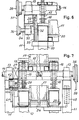
- Figs. 5-7 disclose a modified embodiment of the returning mechanism for the trap doors 24.
- This embodiment comprises a substantially horizontally extending actuating rod 29 which is mounted In slide bearings 30 fastened on the frame 10 so that the rod 29 may be reciprocated in the longitudinal direction of the apparatus.
- a guiding channel member 31 is mounted on and extends vertically downwards from the rod 29, and a stud or roller 32 is in engagement with the channel member 31.
- the stud or roller 32 is eccentrically mounted on and extends from an eccentric disc 33 which is arranged on a shaft 34 extending transversely to the longitudinal direction of the apparatus and rotatably mounted in a bearing 35 which is fastened to the frame 10.
- a pulley or sprocket 36 is mounted on the free end of a shaft 34 and is in driving connection with a corresponding pulley or sprocket 38 on one end of the shaft 14 by means of a belt or chain 37.
- a further pulley or sprocket is mounted at the other end of the shaft 14 and may be connected to a driving motor (not shown) by means of a belt or chain 39.
- the eccentric disc 33 also causes a reciprocating movement of the actuating rod 29.
- the driving members 37 and 39 are in the form of belts they are preferably toothed belts so as to ensure synchronization of the movements of the chains 16 and the trap doors 24.
- Each solenoid or electromagnet 27 Is mounted on a carriage 40 through which the actuating rod 29 extends so as to be dlsplaceable In relation thereto.
- An upwardly and rearwardly extending actuating arm 41 Is fastened to each of the trap doors 24, and the upper end of the actuating arm 41 Is dlsplaceably received In a diametrically extending bore formed in a pivot member 42, which is rotatably mounted in the associated carriage 40.
- a counterweight 48 mounted on an upwardly extending arm is fastened to the other side of each trap door 24 as best shown in Fig. 7.
- Each carriage 40 and the - - solenoid 27 mounted thereon may be displaced between a position which is shown in solid lines in Fig.
- the solenoid 27 When the trap door is to be opened, the solenoid 27 is energized causing the armature 44 of the solenoid to move upwards, whereby the free end of the armature is moved out of engagement with the locking device 43a, and at the same time a stud 46 mounted on and extending from the armature 44 is brought into engagement with a corresponding cut-out 47 in the actuating rod 29.
- the rod 29 When the rod 29 is moved forwards during its reciprocating movement, the carriage 40 and the solenoid 27 mounted thereon will be moved to the right in Fig. 5 to a position indicated by dotted lines, whereby the actuating arm 41 is pivoted clockwise so that the associated trap door 24 is opened.
- Fig. 3 discloses in greater detail an electrode assembly 100 like those Indicated In Fig. 1.
- the electrode assembly comprises a housing 101 defining an upper side surface 102, which constitutes part of the upper and the lower paths of movement, designated 18 and 20, respectively, when the assembly is mounted in the sorting apparatus in the manner shown In Fig. 1.
- a multicore cable 103 extends, of which the individual conductors are shown extending from the end of the insulating jacket of the cable.
- the electrode assembly 100 further comprises two electrode pairs 104 and 105 each including a centre electrode designated 106 and 107, respectively, and preferably made of stainless steel and a graphite electrode designated 108 and 109, respectively, enclosing the corresponding centre electrode 106 and 107, respectively, In relation to which the graphite electrode is insulated.
- Fig. 4 discloses a preferred embodiment of the electronic part of the apparatus including a central control means and electronic measuring amplifier means.
- the central control means is constituted by a microprocessor, which is indicated in Fig. 4 by a block 120.
- the microprocessor 120 is connected to the trap doors 24 and the weight or the weighing unit 23, which is controlled by the microprocessor and from which the microprocessor receives measuring signals, respectively, and two measuring amplifiers 121, which are identical to one another, and which are connected to a corresponding electrode assembly 100, and from which the measuring amplifier 121 in question receives measuring signals.
- one of the measuring amplifiers 121 are shown in detail, viz.
- the electronic part or the electronic circuitry of the sorting apparatus comprises an oscillator 122, which is connected to the two measuring amplifiers 121 through a transformer 123 including a primary winding and two secondary windings, the primary winding of the transformer 123 being connected to the output of the oscillator 122 and the secondary windings of the transformer 123 being connected to each of the measuring amplifiers 121 and to a calibration and offset-compensation circuit 124.
- the signal suppplied from the oscillator is preferably of a frequency of 2 kHz.
- Each of the measuring amplifiers 121 serves the purpose of determining the phase angle between a current which is caused to runthrough the tissue of a fish and the voltage generated by the current across the impedance presented by the tissue of the fish in a manner described In the above mentioned report published by "Torry Research Station", Aberdeen, and further described in British patent specifications Nos. 1,262,749 and 1,287,190.
- the oscillator 122 causes the current to run through the transformer 123 from the graphite electrode 108 of the first electrode pair 104 through the tissue of the fish, which is in contact with the electrode assembly 100 and further through the graphite electrode 109 of the second electrode pair 105 and the primary windings of a connection transformer 125 and back to the oscillator 122 through the first mentioned transformer 123.
- the voltage is measured by means of the centre electrodes 106 and 107 of the electrode pairs 104 and 105, respectively, which are connected to the non-inverting input of an operational amplifier 126 and to the non-inverting input of an operational amplifier 127, respectively, through an appropriate input network.
- the operational amplifiers 126 and 127 are preferably constituted by operational amplifiers of high input impedance, typically of the order of 1.5 T ⁇ (1.5 x 10 12 Q), e.g. of the type comprising a mos-fet input circuit, e.g. an integrated operational amplifier of the type CA 3140.
- the said Input networks of the operational amplifiers 126 and 127 are constituted by three resistors 128, 129, 130 and two diodes 131, 132 and three resistors 133, 134, 135 corresponding to the resistors 128, 129, 130 and two diodes 136, 137 corresponding to the diodes 131, 132, respectively.
- the input networks serve the purpose of providing a DC connection between the measuring electrodes, i.e. the centre electrodes 106 and 107, and the operational amplifiers serve the purpose of providing a short response time during measurement and further to protect the operational amplifiers 126 and 128 against voltages which numerically are larger than the supply voltages plus approximately 0.6 V (a single diode forward voltage drop).
- the operational amplifiers 126 and 127 which are connected in unity-gain mode further comprise a common potentiometer 138 serving the purpose of compensating for input offset voltages of the operational amplifiers.
- the operational amplifiers 126 and 127 are supplied from a positive and a negative voltage supply sourse, which is preferably constituted by a symmetrical voltage supply, e.g. a voltage supply of ⁇ 12 V.
- the outputs of the operational amplifiers 126 and 127 are connected to an inverting and a non-inverting input, respectively, of an operational amplifier 142, which is connected in high-gain mode through resistors 140, 141, respectively.
- an operational amplifier 142 which is connected in high-gain mode through resistors 140, 141, respectively.
- two oppositely directed diodes 143 and 144 are connected, which serve the purpose of limiting the voltages supplied from the operational amplifiers 126 and 127 to approximately ⁇ 0.6-0.7 V ( ⁇ a single diode forward voltage drop) and provide a peak limited, Le.
- a square wave signal which Is supplied to the operational amplifier 142, which, consequently, at Its output supplies a square wave voltage of a frequency Identical to the frequency of the voltage generated across the centre electrodes 106 and 107, the neutral passages of the square wave voltage corresponding to the neutral passages of said voltage.
- the above mentioned alternating current which is induced or caused to run through the tissue of the fish In question produces a voltage across a resistor 145, which is connected to the secondary winding of said connection transformer 125.
- the voltage drop across the resistor 145 is detected by means of an operational amplifier 146 corresponding to the operational amplifier 142 and comprises resistors 147 and 148 corresponding to the resistors 140 and 141, respectively, and diodes 149 and 150 corresponding to the diodes 143 and 144, respectively.
- the operational amplifier 146 produces a square wave voltage at its output the frequency of which is identical to the frequency of the voltage generated across the resistor 145 and consequently identical to the frequency of the current, which is conducted through the tissue of the fish in question, and the neutral passages of which correspond to the neutral passages of the current.
- the outputs of the operational amplifiers 142 and 146 are connected to a respective input of an EXCLUSIVE-OR-gate 153 through appropriate biassing resistors 151 and 152, respectively, the output of the EXCLUSIVE-OR-gate 153 being connected to a first input of a NAND-gate 154.
- a second input of the NAND-gate 154 is connected to the output of a further EXCLUSIVE-OR-gate 155, which will be described in greater detail below.
- the measuring amplifiers 121 include a detector circuit, which serves the purpose of detecting whether a fish is in contact with the corresponding electrode assembly.
- the detector circuit is connected to one of the terminals of the resistor 145, across which a balanced voltage oscillation is generated by the above mentioned alternating current as will be seen from fig. 4 in relation to the ground of the measuring circuit due to the connection transformer 125.
- the detector circuit includes an operational amplifier 160, the non-inverting input of which is connected to the said terminal of the resistor 145 through an input capacitor 161. To the above-mentioned non-inverting input of the operational amplifier 160 and to the inverting input of the operational amplifier 160 grounding resistors 162 and 163, respectively, are connected.
- the operational amplifier 160 which is connected in high-gain mode, has its output connected to a half-wave rectifier and peak value detector circuit comprising a diode 164, two resistors 165 and 166, and a capacitor 167.
- the half-wave rectifier and peak value detector circuit are connected to an Inverter, which Is constituted by a NAND-gate 168, the two Inputs of which are connected to the output of the half-wave rectifier and peak value detector circuit.
- the output of the NAND-gate 168 is, as will be seen from Fig.
- the above described calibration and offset-compensation circuit 124 which is shown in the lower left-hand corner of Fig. 4, comprises a dual gate circuit 169, which is addressed from addressing outputs C and D, respectively, of the microprocessor 120 corresponding to the measuring amplifier 121, shown in the upper part of Fig. 4, and the measuring amplifier 121, shown in the lower part of Fig. 4, respectively.
- the dual gate circuit 169 activates a relay 170 and a relay 171, respectively.
- diodes 172 and 173 respectively, are connected, which serve the purpose of extinguishing induction currents in the corresponding windings of the relays.
- the relay 170 switches a pair of switches 174, whereas by activation the relay 171 switches a pair of switches 175, which connect three resistors 176, 177 and 178, as Is illustrated in Fig. 4, across the electrodes of the corresponding electrode assembly, the resistor 176 being connected across the electrodes of the electrode pair 104, the resistor 177 being connected across the centre electrodes 106 and 107 of the electrode pairs 104 and 105, respectively, and the resistor 178 being connected across the electrodes of the electrode pair 105.
- the circuit shown in Fig. 4 functions in the folowing manner. Initially, i.e. before a fish is arranged in contact with the electrodes of an electrode assembly, the switches 174 and 175 are in the positions shown in Fig. 4, i.e. the calibration resistors 176, 177, 178 are not connected across any of the electrodes of the electrode assemblies. When a fish is brought into contact with an electrode assembly, i.e. the electrode assembly which is connected to the measuring amplifier shown in greater detail the current circuit or current half between the graphite electrodes 108 and 109 of the electrode pairs 104 and 105, respectively, is established, which results in a voltage drop across the resistor 145.
- the voltage drop is detected by the detector circuit including the operational amplifier 160 and the inverter 168, the output of which shifts from high to low.
- the control input of the microprocessor 120 which is connected to the output of the inverter 168, is consequently shifted to low, which corresponds to the detection of a fish in contact with the corresponding electrode assembly.
- the output of the EXC LU -SIVE-OR-gate 155 is simultaneously shifted from low to high. Thereafter, the measuring amplifier Is ready to supply measuring pulses from the output of the NAND-gate 1 54 to the microprocessor 120.
- the microprocessor 1 20 addresses the relay 170 through the C-output so as to connect the resistors 176, 177 , 178 across the corresponding electrode assembly 100 in order to calibrate the measuring amplifier circuit.
- the measurement of the phase angle between current and voltage is effected by the EXCLUSIVE-OR-gate 153 shifting its output to high, when the operational amplifiers 142 and 146 are supplied with signals of different logical levels corresponding to a phase difference between current and voltage.
- the NAND-gate 154 shifts to low, which corresponds to the presence of a phase difference between current and voltage. While the output of the NAND-gate 154 is low, the basic phase difference or phase angle measurement is carried out in the microprocessor 120. Since the frequency of the signal supplied from the oscillator 122 is a fixed frequency, the time difference between current and voltage constitutes a measure of the phase angle.
- the microprocessor 120 After the conclusion of the determination of the degree of freshness of the fish at one side of the fish by means of the first measuring assembly 100 and the corresponding measuring amplifier 121, the result of the measurement is stored in the microprocessor 120, and as described above with reference to fig. 1 the fish is transferred in the continuous operation of the sorting apparatus to a weighing unit 23, which supplies a signal representing the weight of the fish in question to the microprocessor 120, in which the signal representing the weight is stored, and, thereafter, the degree of freshness of the fish at its other side is determined by means of the other measuring assembly and the corresponding measuring apparatus 121, and the result of the second determination is also stored in the microprocessor 120.
- the microprocessor 120 determines which one of the trap doors 24 is to be addressed and addresses the trap door in question.
- the function of the trap doors 24 may be controlled in any other suitable manner than the one shown in the drawings and described above, and the sorting may be based on other criteria than freshness and weight. It is also possible to perform the sorting on the basis of freshness exclusively, and in that case the apparatus needs only a single trap door. In that case the apparatus may, for example, form part of a conveyor system by means of which the fish 19 or the pieces of food are transported to a processing station. In this manner it may be ensured that only completely fresh goods are processed further.
Applications Claiming Priority (2)
| Application Number | Priority Date | Filing Date | Title |
|---|---|---|---|
| DK23/85 | 1985-01-02 | ||
| DK2385A DK2385A (da) | 1985-01-02 | 1985-01-02 | Fremgangsmaade og apparat til bestemmelse af friskhedsgraden for koedstykker og andre foedevareenheder |
Publications (1)
| Publication Number | Publication Date |
|---|---|
| EP0187392A1 true EP0187392A1 (de) | 1986-07-16 |
Family
ID=8088868
Family Applications (1)
| Application Number | Title | Priority Date | Filing Date |
|---|---|---|---|
| EP85116669A Withdrawn EP0187392A1 (de) | 1985-01-02 | 1985-12-31 | Verfahren und Vorrichtung zur Bestimmung des Frischegrades von Fischen oder anderen Fleischstücken |
Country Status (6)
| Country | Link |
|---|---|
| US (1) | US4758778A (de) |
| EP (1) | EP0187392A1 (de) |
| CA (1) | CA1246224A (de) |
| DK (1) | DK2385A (de) |
| IS (1) | IS3056A7 (de) |
| NO (1) | NO855283L (de) |
Cited By (6)
| Publication number | Priority date | Publication date | Assignee | Title |
|---|---|---|---|---|
| WO1993014400A1 (en) * | 1992-01-14 | 1993-07-22 | University Of Alaska | Method and apparatus for detection of defects in food |
| FR2686698A1 (fr) * | 1992-01-28 | 1993-07-30 | Girardeau Francois | Dispositif electronique pour effectuer des analyses de materiaux gazeux, liquides ou solides. |
| GB2298923A (en) * | 1995-03-11 | 1996-09-18 | Central Research Lab Ltd | Sensing the condition of a sample of food |
| ES2130939A1 (es) * | 1996-06-04 | 1999-07-01 | Nte Sa | Aparato para controlar la calidad tecnologica de la carne. |
| WO2014180568A1 (de) * | 2013-05-08 | 2014-11-13 | Freshdetect Gmbh | Messgerät zum messen eines oberflächenbelags auf einem messobjekt, insbesondere auf einem lebensmittel |
| US9952167B1 (en) | 2014-03-07 | 2018-04-24 | Seafood Analytics | Method and device to aid in the inspection and certification of harvested food for human consumption |
Families Citing this family (23)
| Publication number | Priority date | Publication date | Assignee | Title |
|---|---|---|---|---|
| US4980294A (en) * | 1989-09-01 | 1990-12-25 | National Research Council Of Canada/Conseil National De Recherches Du Canada | Method for testing the freshness of fish |
| DE4307082A1 (de) * | 1993-03-06 | 1994-09-08 | Guetermann & Co | Verfahren und Vorrichtung zur elektronischen Mengenerfassung an Verkaufsgeräten |
| AU753473B2 (en) * | 1998-04-30 | 2002-10-17 | Scanvaegt International A/S | Method and system for portioning and orientating whole fish or other elongate, non-symetrical articles |
| US20060161073A1 (en) * | 2001-05-03 | 2006-07-20 | Singer Michael G | In vitro and in vivo assessment of organs and tissue and use, transplant, freshness and tissue conditions |
| US20070104840A1 (en) * | 2001-05-03 | 2007-05-10 | Singer Michael G | Method and system for the determination of palatability |
| US6823212B2 (en) | 2001-06-13 | 2004-11-23 | The Procter & Gamble Company | Method and apparatus for measuring properties of a target surface |
| DE10137651A1 (de) * | 2001-08-03 | 2003-02-27 | Nordischer Maschinenbau | Verfahren zur automatisierten Verarbeitung von Fischen und Anlage zum Aufbereiten und Verarbeiten von Fischen, insbesondere zum Schlachten und Entweiden derselben |
| DK2308327T3 (da) * | 2001-10-31 | 2012-09-03 | Marel Townsend Further Proc Bv | Tromletransportør og fremgangsmåde til transport af frit strømmende belægningsmateriale fra en nedre påfyldningsposition til en øvre frigørelsesposition samt tilsvarende belægningsindretning |
| FR2880124B1 (fr) * | 2004-12-23 | 2007-04-06 | Agronomique Inst Nat Rech | Capteur multielectrodes de mesure d'une anisotropie electrique d'un materiau biologique et utilisation du capteur |
| IS2320B (is) * | 2006-01-23 | 2007-11-15 | Valka Ehf. | Tæki til flokkunar á hlutum |
| WO2008147988A1 (en) * | 2007-05-23 | 2008-12-04 | Singer Michaeal G | Determination of the safety of foodstuffs for consumption |
| US20080306402A1 (en) * | 2006-09-25 | 2008-12-11 | Singer Michaeal G | Method and system for determining vitality, healing and condition of tissue or organ for surgery |
| US20100086655A1 (en) * | 2007-05-23 | 2010-04-08 | Michaeal G Singer | Process of selecting a preparation method, a packaging and shipping method, or other dispostion of a foodstuff, and process of determining if a foodstuff is fresh or has previously been frozen |
| CA2958171C (en) | 2007-11-19 | 2018-09-18 | Timothy A. Burke | Seafood physical characteristic estimation system and method |
| AR068908A1 (es) | 2008-10-17 | 2009-12-16 | Consejo Nac Invest Cient Tec | Procedimiento para estimar parametros organolepticos de tejidos de origen animal y disposicion para llevar a cabo el mismo |
| US9125422B2 (en) * | 2013-12-26 | 2015-09-08 | Zimplistc Pte. Ltd. | Kicker device and method of using the same |
| JP6362360B2 (ja) * | 2014-03-06 | 2018-07-25 | 大和製衡株式会社 | 魚の品質状態判定装置 |
| WO2016139611A2 (en) | 2015-03-02 | 2016-09-09 | Valka Ehf | Apparatus for processing and grading food articles and related methods |
| US11259531B2 (en) | 2015-03-02 | 2022-03-01 | Valka Ehf | Apparatus for processing and grading food articles and related methods |
| US11357237B2 (en) | 2015-03-02 | 2022-06-14 | Valka Ehf | Apparatus for processing and grading food articles and related methods |
| RU177266U1 (ru) * | 2017-09-04 | 2018-02-14 | Федеральное государственное казенное военное образовательное учреждение высшего образования "Военная академия материально-технического обеспечения имени генерала армии А.В. Хрулёва" Министерства обороны Российской Федерации | Электронный щуп для оценки свежести мясных и рыбных продуктов |
| WO2019089038A1 (en) * | 2017-11-02 | 2019-05-09 | Xinova, LLC | Sorting of food items with electrical impedance tomography |
| GB201906418D0 (en) | 2019-05-07 | 2019-06-19 | Valka Ehf | Conveyor system and method |
Citations (4)
| Publication number | Priority date | Publication date | Assignee | Title |
|---|---|---|---|---|
| DE1084495B (de) * | 1956-06-27 | 1960-06-30 | Dethloff Juergen | Verfahren und Vorrichtung zur Bestimmung des Frischegrades von tierischem Fleischgewebe, vorzugsweise von Nutzfischen |
| US3320946A (en) * | 1962-07-30 | 1967-05-23 | Dethloff | Method and means for testing cellular tissues |
| GB1262749A (en) * | 1969-02-24 | 1972-02-02 | Nat Res Dev | Methods and apparatus for determining the condition of food |
| GB1287190A (en) * | 1970-03-25 | 1972-08-31 | Nat Res Dev | Improvements in or relating to apparatus for determining the condition of food |
Family Cites Families (7)
| Publication number | Priority date | Publication date | Assignee | Title |
|---|---|---|---|---|
| NL92107C (de) * | ||||
| CA742885A (en) * | 1966-09-20 | H. Ulrichs Carl | Method and device for examining the physiological condition of cellular tissues | |
| CA370270A (en) * | 1937-11-30 | Dallas Pollitt Stanley | Electric separator for coal | |
| US2937739A (en) * | 1954-05-27 | 1960-05-24 | Levy Maurice Moise | Conveyor system |
| US4082188A (en) * | 1976-06-23 | 1978-04-04 | Hoffmann-La Roche Inc. | Apparatus for color recognition and defect detection of objects such as capsules |
| US4214663A (en) * | 1977-07-11 | 1980-07-29 | Oscar Lucks Company | Transfer apparatus for selectively transferring objects from a delivery conveyor to selected sections of a receiving conveyor |
| ZA783198B (en) * | 1978-06-05 | 1979-09-26 | Sphere Invest | Improvements relating to sorting systems |
-
1985
- 1985-01-02 DK DK2385A patent/DK2385A/da not_active Application Discontinuation
- 1985-11-29 IS IS3056A patent/IS3056A7/is unknown
- 1985-12-23 NO NO855283A patent/NO855283L/no unknown
- 1985-12-31 CA CA000498825A patent/CA1246224A/en not_active Expired
- 1985-12-31 EP EP85116669A patent/EP0187392A1/de not_active Withdrawn
-
1986
- 1986-01-02 US US06/815,588 patent/US4758778A/en not_active Expired - Fee Related
Patent Citations (4)
| Publication number | Priority date | Publication date | Assignee | Title |
|---|---|---|---|---|
| DE1084495B (de) * | 1956-06-27 | 1960-06-30 | Dethloff Juergen | Verfahren und Vorrichtung zur Bestimmung des Frischegrades von tierischem Fleischgewebe, vorzugsweise von Nutzfischen |
| US3320946A (en) * | 1962-07-30 | 1967-05-23 | Dethloff | Method and means for testing cellular tissues |
| GB1262749A (en) * | 1969-02-24 | 1972-02-02 | Nat Res Dev | Methods and apparatus for determining the condition of food |
| GB1287190A (en) * | 1970-03-25 | 1972-08-31 | Nat Res Dev | Improvements in or relating to apparatus for determining the condition of food |
Cited By (8)
| Publication number | Priority date | Publication date | Assignee | Title |
|---|---|---|---|---|
| WO1993014400A1 (en) * | 1992-01-14 | 1993-07-22 | University Of Alaska | Method and apparatus for detection of defects in food |
| FR2686698A1 (fr) * | 1992-01-28 | 1993-07-30 | Girardeau Francois | Dispositif electronique pour effectuer des analyses de materiaux gazeux, liquides ou solides. |
| GB2298923A (en) * | 1995-03-11 | 1996-09-18 | Central Research Lab Ltd | Sensing the condition of a sample of food |
| GB2298923B (en) * | 1995-03-11 | 1998-07-29 | Central Research Lab Ltd | A device for measuring the phase angle of a sample impedance |
| ES2130939A1 (es) * | 1996-06-04 | 1999-07-01 | Nte Sa | Aparato para controlar la calidad tecnologica de la carne. |
| WO2014180568A1 (de) * | 2013-05-08 | 2014-11-13 | Freshdetect Gmbh | Messgerät zum messen eines oberflächenbelags auf einem messobjekt, insbesondere auf einem lebensmittel |
| CN105209890A (zh) * | 2013-05-08 | 2015-12-30 | 鲜活检测有限责任公司 | 用于测量被测对象上、尤其食品上的表面层的测量仪 |
| US9952167B1 (en) | 2014-03-07 | 2018-04-24 | Seafood Analytics | Method and device to aid in the inspection and certification of harvested food for human consumption |
Also Published As
| Publication number | Publication date |
|---|---|
| DK2385D0 (da) | 1985-01-02 |
| US4758778A (en) | 1988-07-19 |
| NO855283L (no) | 1986-07-03 |
| DK2385A (da) | 1986-07-03 |
| CA1246224A (en) | 1988-12-06 |
| IS3056A7 (is) | 1986-03-25 |
Similar Documents
| Publication | Publication Date | Title |
|---|---|---|
| US4758778A (en) | Method and an apparatus for determining the degree of freshness of pieces of food | |
| EP0148908B1 (de) | Vorrichtung und verfahren zum sortieren von teilen | |
| EP0375366A2 (de) | Verfahren und Vorrichtung zur Bestimmung der Beschaffenheit oder einer Eigenschaft eines nichtmetallischen, leitfähigen Materials mit Hilfe eines elektromagnetischen Wechselfeldes | |
| US4055252A (en) | Container liquid level detector apparatus | |
| US6265882B1 (en) | Apparatus and method for measuring the content of intramuscular fat in carcasses or parts thereof | |
| US5917328A (en) | Container inspection apparatus for determining the wall thickness of non-round containers and associated method | |
| NL8103468A (nl) | Werkwijze en inrichting voor het bepalen van de verouderingstoestand van kunststof produkten. | |
| US6145628A (en) | Food and drink conveying system | |
| US3379306A (en) | Apparatus for inspecting containers for wall thickness distribution | |
| EP1107000A1 (de) | Verfahren und Vorrichtung zur Bestimmung der Härte/Elastizität und/oder anderer Eigenschaften von Gemüsen oder Obst | |
| JP2001116701A (ja) | 非破壊果実選別機 | |
| AU664149B2 (en) | Detection of defects in food by detecting pattern of current flow | |
| JP2820282B2 (ja) | 青果物の内部品質検査装置 | |
| JPS59217524A (ja) | コンベア | |
| NO975760L (no) | Apparat og fremgangsmåte til direktekoplet inspeksjon av elektrisk ledende matvareprodukter | |
| JPS63246639A (ja) | トマト等の熟度判定方法 | |
| JP2001276748A (ja) | 農産物の検査装置 | |
| US20030156281A1 (en) | Calibrator for calibrating a light beam | |
| JPS63259452A (ja) | 青果物の接触および非接触による鮮度判定方法 | |
| JP2002039940A (ja) | 被検出物の空洞化検出方法及びその装置 | |
| GB2123959A (en) | Milk abnormality testing aid | |
| Lange | Experience in the Application of the A. C. Potential Probe Method to Determine Crack Propagation | |
| WO2001059470A1 (en) | Method and apparatus for determining the lean content of meat products | |
| KR20010011419A (ko) | 버킷 컨베이어 | |
| DE29812292U1 (de) | Rüstsatzfreie Vorrichtung zum zielgerichteten Bewegen von elektronischen Bauteilen |
Legal Events
| Date | Code | Title | Description |
|---|---|---|---|
| PUAI | Public reference made under article 153(3) epc to a published international application that has entered the european phase |
Free format text: ORIGINAL CODE: 0009012 |
|
| AK | Designated contracting states |
Kind code of ref document: A1 Designated state(s): DE FR GB IT NL SE |
|
| 17P | Request for examination filed |
Effective date: 19870108 |
|
| 17Q | First examination report despatched |
Effective date: 19880520 |
|
| STAA | Information on the status of an ep patent application or granted ep patent |
Free format text: STATUS: THE APPLICATION IS DEEMED TO BE WITHDRAWN |
|
| 18D | Application deemed to be withdrawn |
Effective date: 19900423 |
|
| RIN1 | Information on inventor provided before grant (corrected) |
Inventor name: KRISTINSSON, BJOERN |