EP0187360B1 - Ensemble mélangeur-moule pour produire des articles d'un mélange réactif à partir d'au moins deux constituants réactifs fluides - Google Patents
Ensemble mélangeur-moule pour produire des articles d'un mélange réactif à partir d'au moins deux constituants réactifs fluides Download PDFInfo
- Publication number
- EP0187360B1 EP0187360B1 EP85116410A EP85116410A EP0187360B1 EP 0187360 B1 EP0187360 B1 EP 0187360B1 EP 85116410 A EP85116410 A EP 85116410A EP 85116410 A EP85116410 A EP 85116410A EP 0187360 B1 EP0187360 B1 EP 0187360B1
- Authority
- EP
- European Patent Office
- Prior art keywords
- cross
- section
- chamber
- gap
- slide
- Prior art date
- Legal status (The legal status is an assumption and is not a legal conclusion. Google has not performed a legal analysis and makes no representation as to the accuracy of the status listed.)
- Expired
Links
Images


Classifications
-
- B—PERFORMING OPERATIONS; TRANSPORTING
- B29—WORKING OF PLASTICS; WORKING OF SUBSTANCES IN A PLASTIC STATE IN GENERAL
- B29C—SHAPING OR JOINING OF PLASTICS; SHAPING OF MATERIAL IN A PLASTIC STATE, NOT OTHERWISE PROVIDED FOR; AFTER-TREATMENT OF THE SHAPED PRODUCTS, e.g. REPAIRING
- B29C44/00—Shaping by internal pressure generated in the material, e.g. swelling or foaming ; Producing porous or cellular expanded plastics articles
- B29C44/34—Auxiliary operations
- B29C44/3442—Mixing, kneading or conveying the foamable material
-
- B—PERFORMING OPERATIONS; TRANSPORTING
- B29—WORKING OF PLASTICS; WORKING OF SUBSTANCES IN A PLASTIC STATE IN GENERAL
- B29C—SHAPING OR JOINING OF PLASTICS; SHAPING OF MATERIAL IN A PLASTIC STATE, NOT OTHERWISE PROVIDED FOR; AFTER-TREATMENT OF THE SHAPED PRODUCTS, e.g. REPAIRING
- B29C67/00—Shaping techniques not covered by groups B29C39/00 - B29C65/00, B29C70/00 or B29C73/00
- B29C67/24—Shaping techniques not covered by groups B29C39/00 - B29C65/00, B29C70/00 or B29C73/00 characterised by the choice of material
- B29C67/246—Moulding high reactive monomers or prepolymers, e.g. by reaction injection moulding [RIM], liquid injection moulding [LIM]
Definitions
- the invention relates to a device for producing molded parts from a flowable reaction mixture
- a device for producing molded parts from a flowable reaction mixture comprising at least two flowable reaction components, consisting of a mixer and a mold, a cross-section having a cross-section having a change in cross-section between the mixing chamber of the mixer and the mold cavity of the mold, and the mold-separating plane along the sprue
- the cross-sectional changes consist of a throttle gap and a settling chamber arranged behind it, and the mold separation plane also runs through the throttling gap and the settling chamber.
- Such devices made of mixer and molding tool are used in particular for the foaming of polyurethane reaction mixtures to give moldings and are, for. B. from the document KUNSTSTOFFBERATER, year 26, July / August 1981, pages 24-26, Frankfurt / Main, DE; Dr. U. Knipp «Production of PUR integral foam parts», Fig.6a, 7; Table 1.2: page 26, column 1, lines 4-16.
- the mixer can be integrated in the molding tool; it can be fixed to the mold as a mixing head; however, it can also be attached to the mold only for the mold filling process.
- a throttle member is connected to the mixing chamber in a mixer in a bore that extends transversely to the guide bore of an ejection piston into a position that throttles the cross-section of the guide bore and releases it into a position, the throttle member has an opening, the cross section of which corresponds at least to the cross section of the ejection piston.
- this mixer fails when used for the production of highly reactive reaction mixtures, which solidify within a few seconds, especially when large mold cavities have to be filled.
- the throttle element When the mixing process is ended, the throttle element must first be brought into its rest position from its working position before the mixing chamber and the subsequent outlet pipe can be emptied by means of the ejection piston. Because of the inertia of the control processes and the play that is inevitably contained in the control system, the movement of the ejection piston can only be initiated when the throttle element has definitely assumed its rest position in order to avoid a collision. Since the movement of the throttle element and the subsequent triggering of the ejection piston take about 1 second, the mixture introduced into the mold cavity and still present in the outlet pipe or in the mixing chamber would at least partially be cured before the cleaning process begins. Of course, this creates difficulties.
- reaction mixture shoots into the mold cavity at high speed. It is not possible to avoid blowing in air.
- the associated tearing open of the flow and spraying can cause boundary surface contours in the case of highly reactive systems during the subsequent re-confluence, which impair the homogeneity of the molded part and reduce the mechanical strength.
- the task is solved in that the calming chamber completely overlaps the sprue and the cross section of the sprue channel expanded at least immediately behind the calming chamber.
- the cross section of the throttle gap is preferably adjustable.
- this measure makes it possible to influence the mixing quality by changing the cross section of the throttle gap.
- Unwanted fluctuations in the room temperature or the temperature of the components also influence the mixing and can be compensated for by the adjustability of the throttle gap.
- an adjustable throttle gap naturally also enables adaptation to various reaction mixtures. It is even possible to exert influence during the mold filling process.
- the throttle gap can be set to zero or almost zero at the beginning of the mixing process in order to bring about a particularly intensive initial mixing, and can only be set to the normal value during the further course of the mixing process.
- the adjustability of the throttle gap can preferably be brought about in that the throttle gap is formed by a slide which is adjustable in its stroke width and a counter surface.
- the slide is designed, for example, as a hydraulic piston and equipped with a stop screw for adjusting the stroke width. If the slide should also be adjustable during the mold filling process, a special adjustment device must be provided for this.
- the calming chamber has the shape of a spherical cap beyond the cross section of the sprue.
- This shape is particularly favorable in terms of flow technology in order to rapidly reduce the higher flow velocity generated in the throttle gap and to convert it into a laminar flow, which then stabilizes in the subsequent section of the sprue.
- the circumferential lines of spherical cap and slide preferably overlap on the side facing the mixing chamber.
- the throttle gap is formed by a recess with a pin extending into it, a first gap between the pin and the wall part of the recess facing the mixing chamber, a throttle gap between the pin and the bottom of the recess and between the pin and the mold cavity located in the wall part of the recess, the calming chamber, the cross section of the throttle gap being larger than that of the first gap and the cross section of the calming chamber being larger than that of the throttle gap.
- the spigot and recess are preferably rectangular.
- the pin can extend sealingly to the side wall parts of the recess, but can also form a gap there.
- the pin preferably consists of a slide that is adjustable in its stroke width, for which the previously explained embodiments can also be used.
- a slide is guided in the depression, the end face of which forms the bottom of the depression.
- This slide can also preferably be made adjustable in its stroke width, so that in combination with a pin designed as a slide, the length of the first gap and at the same time the volume of the calming chamber can be adjusted.
- a plurality of throttle gaps and calming chambers are arranged alternately one behind the other.
- the following throttle gap preferably has a larger cross section than the previous one.
- the following calming chamber also has a larger volume than the previous one.
- step-by-step mixing with speed reduction can be made very targeted.
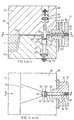
- the combination consists of an attached mixer 1 and a molding tool 2.
- the mixer 1 comprises a housing 3 with a mixing chamber 4, into which injection nozzles 5, 6 for the reaction components open, and an ejection piston 7.
- the mixer 1 is attached to the lower mold half 8. Between the lower mold half 8 and the upper mold half 9, the mold parting plane 10 and a sprue 12 extending from the mixing chamber 4 to a mold cavity 11 extend. It is essentially embedded in the lower mold half 8 and is affected by the mold parting plane 10.
- the sprue 12 narrows from the mixing chamber 4 to a throttle gap 13. This is formed by an adjustable slide 14 and a counter surface 15.
- the counter surface 15 is part of an insert 16 which is fitted into the upper mold half 9 and which has the contour of a spherical cap 17 toward the sprue 12.
- a calming chamber 18 consisting of the volume of the spherical cap 17 and the volume of the section of the sprue 12 located in this area is formed behind the throttle gap 13.
- the circumferential line 20 of the spherical cap 17 and the circumferential line 21 of the slide 14 overlap on their side facing the mixing chamber 4 and thus form a throttle gap 13 of different lengths.
- the slide 14 is designed as a hydraulic piston 23 which can be acted upon on both sides and is guided in a hydraulic chamber 22 and which is provided with an adjustable stop screw 24 for adjusting the stroke width and thus the height of the throttle gap 13.
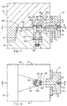
- the mixer 31 comprises a housing 33 with a mixing chamber 34, into which injection nozzles 35, 36 open for the reaction components, and an ejection piston 37.
- the mixer 31 is attached to the lower mold half 38.
- the mold parting plane 40 runs between the lower mold half 38 and the upper mold half 39.
- a sprue 42 extending from the mixing chamber 34 to a mold cavity 41 is essentially embedded in the lower mold half 38 and is affected by the mold parting plane 40.
- the sprue 42 narrows from the mixing chamber 34 to a throttle gap 43. This is formed by an adjustable pin designed as a slide 44 and a counter surface 45, which consists of the end face of a second slide 46.
- the slider 46 forms the bottom 45 of a recess 47 into which the slider 44 projects.
- the slide 44 has a rectangular cross section. It is provided with a hydraulic piston 48, which is guided in a hydraulic chamber 49. The stroke width can be adjusted by means of a stop screw 50. Between itself and the wall part 52 of the recess 47 facing the mixing chamber 34, the slide 44 forms a gap 51 of smaller cross section upstream of the actual throttle gap 43. The gap 51 is unchangeable. Depending on the setting of the slide 44 to 46, however, its length is variable.
- the slide 44 is sealingly adapted to the lateral wall parts 53 of the recess 57.
- a settling chamber 55 extends between the slide 44 and the wall part 54 facing the mold cavity 41. Its volume can be adjusted by adjusting the slide 46.
- the slide 46 is also provided with an ejection piston 57 guided in a hydraulic chamber 56 and an adjustable stop screw 58. The widening and at the same time flattening section 59 of the runner 42 connects to the calming chamber 55.
- One of the sliders 44 and 46 can also be designed as an ejector, for which one appropriate control must be provided. This makes it easier to demould the sprue rod 60 after the mold 32 has been opened.
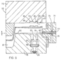
- the combination consists of a mixer 71 and a molding tool 72, the mixer 71 being attached to the molding tool 72.
- the mixer 71 comprises a housing 73 with a mixing chamber 74, into which injection nozzles 75, 76 for the reaction components open, and an ejection piston 77.
- the mixer 71 is fastened to the lower mold half 78.
- the mold parting plane 80 runs between the lower mold half 78 and the upper mold half 79.
- a sprue 82 extending from the mixing chamber 74 to a mold cavity 81 is essentially embedded in the lower mold half 78 and is affected by the mold parting plane 80.
- the runner 82 narrows from the mixing chamber 74 to a throttle gap 83.
- the depression 86 is arranged in the upper mold half 79.
- the slide 84 forms, with the wall part 87 of the recess 86 facing the mixing chamber 74, a fixed gap 88 arranged upstream of the actual throttle gap 83.
- a calming chamber 90 extends between the rear of the slide 84 and the wall part 89 of the recess 86 facing the mold cavity 81.
- the throttle gap 94 is preceded by a fixed gap 95.
- a second calming chamber 96 is arranged behind the slide 92.
- the throttle gap 94 has a larger cross section than the throttle gap 83, and the second calming chamber 96 has a larger volume than the calming chamber 90.
- the slide 92 is also equipped with a larger cross section than the slide 84.
- the sprue channel 82 already widens from the area of the slide 84 at behind the calming chamber 96 to the mold cavity 81.
- the two slides 84 and 92 are arranged on a common hydraulic piston 98, which is guided in a hydraulic chamber 97 and is provided with a stop screw 99.
- the stroke length of the slides 84 and 92 can only be adjusted together.
- the slides 84 and 92 can, however, be of different lengths, so that the throttle gaps 83 and 94 have different heights. It goes without saying that the slides 84 and 92 can also have separate hydraulic drives and are therefore individually adjustable.
- a section 100 of the sprue 82 extends between the settling chamber 90 and the slide 92 and the section 101 extends between the settling chamber 96 and the mold cavity 81.
- the sprue rod remaining in the sprue 82 is designated by 102.
Claims (11)
Applications Claiming Priority (2)
| Application Number | Priority Date | Filing Date | Title |
|---|---|---|---|
| DE3500235 | 1985-01-05 | ||
| DE19853500235 DE3500235A1 (de) | 1985-01-05 | 1985-01-05 | Kombination aus mischer und formwerkzeug zum herstellen von formteilen aus einem fliessfaehigen reaktionsgemisch aus mindestens zwei fliessfaehigen reaktionskomponenten |
Publications (3)
| Publication Number | Publication Date |
|---|---|
| EP0187360A2 EP0187360A2 (fr) | 1986-07-16 |
| EP0187360A3 EP0187360A3 (en) | 1987-06-03 |
| EP0187360B1 true EP0187360B1 (fr) | 1989-07-05 |
Family
ID=6259319
Family Applications (1)
| Application Number | Title | Priority Date | Filing Date |
|---|---|---|---|
| EP85116410A Expired EP0187360B1 (fr) | 1985-01-05 | 1985-12-21 | Ensemble mélangeur-moule pour produire des articles d'un mélange réactif à partir d'au moins deux constituants réactifs fluides |
Country Status (3)
| Country | Link |
|---|---|
| US (1) | US4680003A (fr) |
| EP (1) | EP0187360B1 (fr) |
| DE (2) | DE3500235A1 (fr) |
Families Citing this family (15)
| Publication number | Priority date | Publication date | Assignee | Title |
|---|---|---|---|---|
| DE3613076A1 (de) * | 1986-04-18 | 1987-10-29 | Bayer Ag | Verfahren und vorrichtung zum herstellen von massiven oder geschaeumten formteilen aus einem fliessfaehigen reaktionsgemisch |
| JPH0337931Y2 (fr) * | 1986-04-30 | 1991-08-12 | ||
| US4840556A (en) * | 1987-07-16 | 1989-06-20 | Extrusion Punch & Tool Co. | Mixing plate for injection molding machine |
| DE3736022A1 (de) * | 1987-10-24 | 1989-05-03 | Hennecke Gmbh Maschf | Vorrichtung zum herstellen von formteilen aus einem zu kunststoff, insbesondere schaumkunststoff, ausreagierenden, fliessfaehigen reaktionsgemisch aus fliessfaehigen reaktionskomponenten |
| US5049055A (en) * | 1987-12-31 | 1991-09-17 | Sanken Electric Co., Ltd. | Mold assembly |
| US5133921A (en) * | 1987-12-31 | 1992-07-28 | Sanken Electric Co., Ltd. | Method for manufacturing plastic encapsulated electronic semiconductor devices |
| US5101882A (en) * | 1990-03-14 | 1992-04-07 | Chrysler Corporation | Die cast vacuum valve system |
| US5498151A (en) * | 1993-05-05 | 1996-03-12 | Nennecker; Gunter H. | Mixing head for molding machine |
| US5536286A (en) * | 1994-09-26 | 1996-07-16 | Freeman; Lewis G. | Vacuum valve filtering system |
| US5540272A (en) * | 1994-09-26 | 1996-07-30 | Freeman; Lewis G. | Die cast vacuum valve |
| US5586596A (en) * | 1994-09-26 | 1996-12-24 | Freeman; Lewis G. | Die cast vent block |
| US5538069A (en) * | 1994-09-26 | 1996-07-23 | Freeman; Lewis G. | Die cast vacuum valve |
| JP2007515317A (ja) * | 2003-12-23 | 2007-06-14 | デコマ インターナショナル インコーポレイテッド | 蒸気箱金型で発泡プラスチック材料を成形する成形物品、方法、および装置 |
| TW201233521A (en) * | 2011-02-01 | 2012-08-16 | Quanta Comp Inc | Plastic material injection molding system |
| CN110893692B (zh) | 2018-09-13 | 2022-05-24 | 德斯马制鞋设备有限公司 | 具有压力相关阀的注射成型系统 |
Family Cites Families (15)
| Publication number | Priority date | Publication date | Assignee | Title |
|---|---|---|---|---|
| US2313004A (en) * | 1939-10-02 | 1943-03-02 | Pritchard Percy | Casting of metals |
| CH512987A (de) * | 1969-09-04 | 1971-09-30 | Buehler Ag Geb | Verfahren und Vorrichtung zum Spritzgiessen von Kunststoff zu geschäumten Gegenständen |
| US3819313A (en) * | 1970-04-02 | 1974-06-25 | Allied Chem | Apparatus for molding articles |
| DE2252201A1 (de) * | 1972-10-25 | 1974-05-22 | 5090 Leverkusen | Vorrichtung zum herstellen von formteilen aus schnell miteinander reagierenden chemischen komponenten |
| AT351243B (de) * | 1973-09-14 | 1979-07-10 | Demag Kunststofftech | Angussvorrichtung fuer giessformen zur herstellung von gegenstaenden von aus mehreren fluessigen komponenten sich bildenden kunststoffen |
| DE2348608C3 (de) * | 1973-09-27 | 1980-09-18 | Bayer Ag, 5090 Leverkusen | Vorrichtung zum Herstellen von Schaum- oder Homogenstoffen aus fließfähigen Reaktionskomponenten |
| US3897929A (en) * | 1974-08-12 | 1975-08-05 | Nat Tool And Manufacturing Co | Recessed sprue bushing for a three-plate mold set |
| US4067673A (en) * | 1975-09-02 | 1978-01-10 | Ex-Cell-O Corporation | Apparatus for injection foam molding |
| DE2612812C3 (de) * | 1976-03-25 | 1983-05-26 | Bayer Ag, 5090 Leverkusen | Mischkopf zum Vermischen mindestens zweier bei ihrer Reaktion Schaumstoff bildender Komponenten |
| DE2737616A1 (de) * | 1977-08-20 | 1979-03-01 | Bayer Ag | Verfahren und vorrichtung zum herstellen eines schaumstoff- oder homogenstoff-bildenden reaktionsgemisches und zu dessen anschliessendem eintrag in einen hohlraum |
| DE2934354A1 (de) * | 1979-08-24 | 1981-03-26 | Bayer Ag, 51373 Leverkusen | Verfahren zum fuellen von hohlraeumen, insbesondere solcher von formwerkzeugen, mit einem reaktionsfaehigen, fliessfaehigen gemisch |
| US4446088A (en) * | 1981-09-08 | 1984-05-01 | Mobil Oil Corporation | Method and mold for making an improved egg carton |
| DE3216647A1 (de) * | 1982-05-04 | 1983-11-10 | Elastogran Maschinenbau GmbH, 2844 Lemförde | Mischvorrichtung fuer mehrkomponentenkunststoffe |
| DE3341308A1 (de) * | 1982-11-16 | 1984-05-17 | Basf Ag, 6700 Ludwigshafen | Im angusskanal integrierter nachmischer fuer geteilte giessformen |
| DE3478211D1 (en) * | 1983-09-03 | 1989-06-22 | Hennecke Gmbh Maschf | Multiple nozzle for bringing together at least two free-flowing reactants forming plastic, in particular foamed plastic, in order to start the reaction by mixing, and method of operating said multiple nozzle |
-
1985
- 1985-01-05 DE DE19853500235 patent/DE3500235A1/de not_active Withdrawn
- 1985-12-20 US US06/811,254 patent/US4680003A/en not_active Expired - Fee Related
- 1985-12-21 DE DE8585116410T patent/DE3571310D1/de not_active Expired
- 1985-12-21 EP EP85116410A patent/EP0187360B1/fr not_active Expired
Also Published As
| Publication number | Publication date |
|---|---|
| DE3500235A1 (de) | 1986-07-10 |
| US4680003A (en) | 1987-07-14 |
| EP0187360A2 (fr) | 1986-07-16 |
| EP0187360A3 (en) | 1987-06-03 |
| DE3571310D1 (en) | 1989-08-10 |
Similar Documents
| Publication | Publication Date | Title |
|---|---|---|
| EP0187360B1 (fr) | Ensemble mélangeur-moule pour produire des articles d'un mélange réactif à partir d'au moins deux constituants réactifs fluides | |
| EP0137250B1 (fr) | Buse multiple pour réunir au moins deux réactants fluides formant de la matière plastique, en particulier de la matière plastique alvéolaire, en vue de déclencher la réaction par mélange et procédé pour le fonctionnement de ladite buse multiple | |
| EP0024608B2 (fr) | Procédé et dispositif de production de pièces moulées à partir d'un mélange fluide réactionnel formant une matière pleine ou expansée | |
| DE2513492C3 (de) | Vorrichtung zum Vermischen eines flüssigen Treibmittels mit niedrigem Siedepunkt mit weiteren Komponenten zur Herstellung von Schaumstoff | |
| EP0261350B1 (fr) | Dispositif pour fabriquer des pièces moulées en matière plastique | |
| EP0024610B1 (fr) | Procédé pour le remplissage d'espaces creux d'outils de formage avec un mélange réactionnel à partir d'au moins deux composants réactionnels fluides formant une matière plastique compacte | |
| DE2342794B2 (de) | Verfahren und Vorrichtung zum diskontinuierlichen Herstellen von Mehrschicht-Formteilen aus thermoplastischem Kunststoff | |
| EP0099045B1 (fr) | Méthode et tête de mélange pour la fabrication d'un mélange ayant au moins deux composants réactifs pouvant couler et formant une matière plastique | |
| DE2346135A1 (de) | Verfahren und vorrichtung zum diskontinuierlichen herstellen von mehrschichtformteilen aus thermoplastischem kunststoff | |
| EP0310914A2 (fr) | Procédé pour mouler par injection des pièces en matière synthétique thermoplastique ainsi que dispositif pour la réalisation du procédé | |
| DE60209505T3 (de) | Verfahren zum spritzgiessen | |
| DE3014175A1 (de) | Verfahren und vorrichtung zum einspritzmischen und -abgeben fuer hochgeschwindigkeitsreaktionen | |
| EP0260564B1 (fr) | Procédé et dispositif pour la fabrication en continu d'une matière plastique, en particulier d'un mélange réactif liquide formant une mousse à partir d'au moins deux composants liquides | |
| EP0070486B1 (fr) | Procédé et dispositif pour produire un mélange réactionnel de composants fluides au moins avec deux composantes de réaction capables de couler, réagissantes ensemble pour devenir une matière homogène ou de mousse | |
| EP0084672B1 (fr) | Dispositif pour produire d'un mélange chimiquement réactif à partir d'au moins deux composants d'une matière synthétique | |
| DE10136243B4 (de) | Ventilanordnung zur Steuerung der Zudosierung von fluiden Additiven in eine Kunststoffschmelze | |
| DE2623308B2 (de) | Vorrichtung zum diskontinuierlichen Herstellen von Formteilen aus thermoplastischem Kunststoff | |
| DE3521236A1 (de) | Mischkopf zum vermischen zumindest zweier kunststoff bildender komponenten | |
| DE2544749A1 (de) | Mit einem mischkopf kombiniertes formwerkzeug zum herstellen von formteilen | |
| EP0088936B1 (fr) | Tête de mélange pour produire un mélange de préférence à réaction chimique en au moins deux composants de matières synthétiques | |
| DE19819833A1 (de) | Verfahren und Vorrichtung zum Einspritzen von Kunststoffmaterial | |
| DE102007045439B3 (de) | Vorrichtung zum Durchmischen oder Filtern von Schmelze an einer Spritzgießmaschine | |
| DE4009465C2 (de) | Vorrichtung zum mischen von wenigstens zwei reaktiven kunststoffkomponenten | |
| DE4216393C2 (de) | Nachmischer für Formwerkzeuge der RIM-Technik | |
| EP0564908A1 (fr) | Dispositif pour mélanger des composants de réaction réagissant entre eux |
Legal Events
| Date | Code | Title | Description |
|---|---|---|---|
| PUAI | Public reference made under article 153(3) epc to a published international application that has entered the european phase |
Free format text: ORIGINAL CODE: 0009012 |
|
| 17P | Request for examination filed |
Effective date: 19851221 |
|
| AK | Designated contracting states |
Kind code of ref document: A2 Designated state(s): DE FR GB IT |
|
| PUAL | Search report despatched |
Free format text: ORIGINAL CODE: 0009013 |
|
| AK | Designated contracting states |
Kind code of ref document: A3 Designated state(s): DE FR GB IT |
|
| 17Q | First examination report despatched |
Effective date: 19871210 |
|
| GRAA | (expected) grant |
Free format text: ORIGINAL CODE: 0009210 |
|
| AK | Designated contracting states |
Kind code of ref document: B1 Designated state(s): DE FR GB IT |
|
| ITF | It: translation for a ep patent filed |
Owner name: ING. C. GREGORJ S.P.A. |
|
| GBT | Gb: translation of ep patent filed (gb section 77(6)(a)/1977) | ||
| REF | Corresponds to: |
Ref document number: 3571310 Country of ref document: DE Date of ref document: 19890810 |
|
| ET | Fr: translation filed | ||
| PLBE | No opposition filed within time limit |
Free format text: ORIGINAL CODE: 0009261 |
|
| STAA | Information on the status of an ep patent application or granted ep patent |
Free format text: STATUS: NO OPPOSITION FILED WITHIN TIME LIMIT |
|
| 26N | No opposition filed | ||
| ITTA | It: last paid annual fee | ||
| PGFP | Annual fee paid to national office [announced via postgrant information from national office to epo] |
Ref country code: DE Payment date: 19951114 Year of fee payment: 11 |
|
| PGFP | Annual fee paid to national office [announced via postgrant information from national office to epo] |
Ref country code: FR Payment date: 19951129 Year of fee payment: 11 |
|
| PGFP | Annual fee paid to national office [announced via postgrant information from national office to epo] |
Ref country code: GB Payment date: 19951212 Year of fee payment: 11 |
|
| PG25 | Lapsed in a contracting state [announced via postgrant information from national office to epo] |
Ref country code: GB Effective date: 19961221 |
|
| GBPC | Gb: european patent ceased through non-payment of renewal fee |
Effective date: 19961221 |
|
| PG25 | Lapsed in a contracting state [announced via postgrant information from national office to epo] |
Ref country code: FR Effective date: 19970829 |
|
| PG25 | Lapsed in a contracting state [announced via postgrant information from national office to epo] |
Ref country code: DE Effective date: 19970902 |
|
| REG | Reference to a national code |
Ref country code: FR Ref legal event code: ST |