EP0187360B1 - Mixer mould combination for producing articles from a fluidic reactive mixture of at least two fluidic reactive components - Google Patents
Mixer mould combination for producing articles from a fluidic reactive mixture of at least two fluidic reactive components Download PDFInfo
- Publication number
- EP0187360B1 EP0187360B1 EP85116410A EP85116410A EP0187360B1 EP 0187360 B1 EP0187360 B1 EP 0187360B1 EP 85116410 A EP85116410 A EP 85116410A EP 85116410 A EP85116410 A EP 85116410A EP 0187360 B1 EP0187360 B1 EP 0187360B1
- Authority
- EP
- European Patent Office
- Prior art keywords
- cross
- section
- chamber
- gap
- slide
- Prior art date
- Legal status (The legal status is an assumption and is not a legal conclusion. Google has not performed a legal analysis and makes no representation as to the accuracy of the status listed.)
- Expired
Links
Images


Classifications
-
- B—PERFORMING OPERATIONS; TRANSPORTING
- B29—WORKING OF PLASTICS; WORKING OF SUBSTANCES IN A PLASTIC STATE IN GENERAL
- B29C—SHAPING OR JOINING OF PLASTICS; SHAPING OF MATERIAL IN A PLASTIC STATE, NOT OTHERWISE PROVIDED FOR; AFTER-TREATMENT OF THE SHAPED PRODUCTS, e.g. REPAIRING
- B29C44/00—Shaping by internal pressure generated in the material, e.g. swelling or foaming ; Producing porous or cellular expanded plastics articles
- B29C44/34—Auxiliary operations
- B29C44/3442—Mixing, kneading or conveying the foamable material
-
- B—PERFORMING OPERATIONS; TRANSPORTING
- B29—WORKING OF PLASTICS; WORKING OF SUBSTANCES IN A PLASTIC STATE IN GENERAL
- B29C—SHAPING OR JOINING OF PLASTICS; SHAPING OF MATERIAL IN A PLASTIC STATE, NOT OTHERWISE PROVIDED FOR; AFTER-TREATMENT OF THE SHAPED PRODUCTS, e.g. REPAIRING
- B29C67/00—Shaping techniques not covered by groups B29C39/00 - B29C65/00, B29C70/00 or B29C73/00
- B29C67/24—Shaping techniques not covered by groups B29C39/00 - B29C65/00, B29C70/00 or B29C73/00 characterised by the choice of material
- B29C67/246—Moulding high reactive monomers or prepolymers, e.g. by reaction injection moulding [RIM], liquid injection moulding [LIM]
Landscapes
- Engineering & Computer Science (AREA)
- Mechanical Engineering (AREA)
- Injection Moulding Of Plastics Or The Like (AREA)
- Processing And Handling Of Plastics And Other Materials For Molding In General (AREA)
Description
Die Erfindung richtet sich auf eine Vorrichtung zum Herstellen von Formteilen aus einem fliessfähigen Reaktionsgemisch aus mindestens zwei fliessfähigen Reaktionskomponenten, bestehend aus Mischer und Formwerkzeug, wobei sich zwischen der Mischkammer des Mischers und dem Formhohlraum des Formwerkzeuges ein Querschnittveränderungen aufweisender Angusskanal erstreckt und die Formtrennebene entlang des Angusskanals verläuft, wobei die Querschnittsveränderungen aus einem Drosselspalt und einer dahinter angeordneten Beruhigungskammer bestehen und die Formtrennebene auch durch den Trosselspalt und die Beruhigungskammerverläuft.The invention relates to a device for producing molded parts from a flowable reaction mixture comprising at least two flowable reaction components, consisting of a mixer and a mold, a cross-section having a cross-section having a change in cross-section between the mixing chamber of the mixer and the mold cavity of the mold, and the mold-separating plane along the sprue The cross-sectional changes consist of a throttle gap and a settling chamber arranged behind it, and the mold separation plane also runs through the throttling gap and the settling chamber.
Derartige Vorrichtungen aus Mischer und Formwerkzeug dienen insbesondere der Formverschäumung von Polyurethan-Reaktionsgemischen zu Formteilen und sind z. B. aus dem Dokument KUNSTSTOFFBERATER, Jahrgang 26, Juli/ August 1981, Seiten 24-26, Frankfurt/Main, DE; Dr. U. Knipp «Herstellung von PUR-Integralschaumteilen», Fig.6a, 7; Tabelle 1.2: Seite 26, Spalte 1, Zeilen 4-16, ersichtlich.Such devices made of mixer and molding tool are used in particular for the foaming of polyurethane reaction mixtures to give moldings and are, for. B. from the document KUNSTSTOFFBERATER, year 26, July / August 1981, pages 24-26, Frankfurt / Main, DE; Dr. U. Knipp «Production of PUR integral foam parts», Fig.6a, 7; Table 1.2: page 26,
Eine solche Kombination kann verschiedenartig gestaltet sein: Der Mischer kann in das Formwerkzeug integriert sein; er kann als Aufbaumischkopf am Formwerkzeug fixiert sein; er kann aber auch nur für den Formfüllvorgang an das Formwerkzeug ansetzbar sein.Such a combination can be designed in different ways: the mixer can be integrated in the molding tool; it can be fixed to the mold as a mixing head; however, it can also be attached to the mold only for the mold filling process.
Bei einer solchen Kombination ist es heute selbstverständlich, dass der Mischer selbstreinigend arbeiet oder dass der in der Mischkammer verbleibende Gemischrest mit entformbar ist. Mischer, welche gespült werden müssen, sind früher für derartige Zwecke verwendet worden, werden aber wegen der reinigungstechnischen Prblematik und allen damit verbundenen Nachteilen heute nicht mehr eingesetzt.With such a combination, it goes without saying today that the mixer works self-cleaning or that the mixture residue remaining in the mixing chamber can also be removed from the mold. Mixers that have to be rinsed were previously used for such purposes, but are no longer used due to the cleaning problems and all the disadvantages associated with them.
Aus DE-A 2612812 (entsprechend US-A 4141 470) ist bei einem Mischer anschliessend an die Mischkammer ein Drosselorgan in einer sich quer zur Führungsbohrung eines Ausstosskolbens erstreckenden Bohrung in eine den Querschnitt der Führungsbohrung drosselnde und eine diese freigebende Stellung bewegbar, wobei das Drosselorgan einen Durchbruch aufweist, dessen Querschnitt mindestens dem Querschnitt des Ausstosskolbens entspricht. Mittels des Drosselorgans ist es möglich, den Mischkammerdruck und die Austrittsgeschwindigkeit des Reaktionsgemisches aus der Mischkammer zu beeinflussen, eine Nachvermischung zu erzielen und in einem anschliessenden Auslaufrohr eine Strömungsberuhigung herbeizuführen. Dieser Mischer versagt aber beim Einsatz für die Herstellung hochreaktiver Reaktionsgemische, welche sich innerhalb weniger Sekunden verfestigen, insbesondere dann, wenn grosse Formhohlräume zu füllen sind. Mit Beenden des Mischvorganges muss das Drosselorgan nämlich aus seiner Arbeitsstellung zunächst in Ruhestellung gebracht werden, bevor mittels des Ausstosskolbens die Mischkammer und das anschliessende Auslaufrohr entleert werden können. Wegen der Trägheit der Steuerungsvorgänge und des im Steuersystem zwangsläufig enthaltenen Spiels kann die Bewegung des Ausstosskolbens erst eingeleitet werden, wenn das Drosselorgan mit Sicherheit seine Ruhestellung eingenommen hat, um eine Kollision zu vermeiden. Da die Bewegung des Drosselorgans und die anschliessende Auslösung des Ausstosskolbens etwa 1 Sekunde in Anspruch nimmt, wäre das in den Formhohlraum eingebrachte und noch im Auslaufrohr bzw. in der Mischkammer vorhandene Gemisch zumindest bereits teilweise ausgehärtet, bevor der Reinigungsvorgang einsetzt. Damit treten natürlich Schwierigkeiten auf.From DE-A 2612812 (corresponding to US-A 4141 470), a throttle member is connected to the mixing chamber in a mixer in a bore that extends transversely to the guide bore of an ejection piston into a position that throttles the cross-section of the guide bore and releases it into a position, the throttle member has an opening, the cross section of which corresponds at least to the cross section of the ejection piston. By means of the throttling device, it is possible to influence the mixing chamber pressure and the exit speed of the reaction mixture from the mixing chamber, to achieve post-mixing and to bring about a flow settling in a subsequent outlet pipe. However, this mixer fails when used for the production of highly reactive reaction mixtures, which solidify within a few seconds, especially when large mold cavities have to be filled. When the mixing process is ended, the throttle element must first be brought into its rest position from its working position before the mixing chamber and the subsequent outlet pipe can be emptied by means of the ejection piston. Because of the inertia of the control processes and the play that is inevitably contained in the control system, the movement of the ejection piston can only be initiated when the throttle element has definitely assumed its rest position in order to avoid a collision. Since the movement of the throttle element and the subsequent triggering of the ejection piston take about 1 second, the mixture introduced into the mold cavity and still present in the outlet pipe or in the mixing chamber would at least partially be cured before the cleaning process begins. Of course, this creates difficulties.
Andererseits ist es aus der DE-A 3 216 647 (entsprechend EP-A 0093356) bekannt, bei einer Kombination von Mischer mit Formwerkzeug im Anschluss an die Mischkammer im Angusskanal eine wesentliche Reduzierung des Querschnittes gegenüber der Mischkammer vorzunehmen und mehrfache Umlenkungen und Querschnittsänderungen vorzusehen, um durch die damit hervorgerufenen Änderungen der Strömungsverhältnisse eine Nachvermischung des Reaktionsgemisches zu erreichen. Bei diesem Mischer kann der Reinigungsvorgang schneller eingeleitet werden, weil kein verschiebbares Drosselorgan am Ausgang der Mischkammer vorhanden ist. Die im Angusskanal vorgesehenen Querschnittsänderungen und Umlenkungen sind aber so ausgebildet, dass sie lediglich eine Nachvermischung bewirken. Eine Beruhigungsstrecke ist nicht vorhanden. Wegen der starken Umlenkungen schiesst das Reaktionsgemisch mit hoher Geschwindigkeit in den Formhohlraum. Dabei lässt sich das Einschlagen von Luft nicht vermeiden. Das damit verbundene Aufreissen der Strömung und Spritzen kann gerade bei hochreaktiven Systemen beim anschliessenden Wiederzusammenfliessen innerhalb des Formteils Grenzflächenkonturen verursachen, welche die Homogenität des Formteils beeinträchtigen und die mechanische Festigkeit herabsetzen.On the other hand, it is known from DE-A 3 216 647 (corresponding to EP-A 0093356) that in the case of a combination of mixer and molding tool following the mixing chamber in the sprue channel, the cross-section is substantially reduced compared to the mixing chamber and multiple deflections and cross-sectional changes are provided, in order to achieve post-mixing of the reaction mixture through the changes in the flow conditions caused thereby. With this mixer, the cleaning process can be initiated more quickly because there is no movable throttle element at the outlet of the mixing chamber. However, the cross-sectional changes and deflections provided in the sprue are designed in such a way that they only cause re-mixing. There is no calming section. Because of the strong deflections, the reaction mixture shoots into the mold cavity at high speed. It is not possible to avoid blowing in air. The associated tearing open of the flow and spraying can cause boundary surface contours in the case of highly reactive systems during the subsequent re-confluence, which impair the homogeneity of the molded part and reduce the mechanical strength.
Es besteht die Aufgabe, ebenso wie bei den bisher bekannten Kombinationen aus Mischer und Formwerkzeug den Mischkammerdruck und die Austrittsgeschwindigkeit des Reaktionsgemisches aus der Mischkammer beeinflussen zu können und eine Nachvermischung zu ermöglichen, wobei aber auch hochreaktive Systeme, also solche, welche innerhalb weniger Sekunden aushärten, verarbeitbar sind.It is the task, as with the previously known combinations of mixer and molding tool, to be able to influence the mixing chamber pressure and the exit speed of the reaction mixture from the mixing chamber and to enable postmixing, but also highly reactive systems, i.e. those which harden within a few seconds, are processable.
Besonderes Augenmerk ist dabei auf die Strömungsberuhigung zu richten, damit beim Formfüllvorgang eine geschlossene Fliessfront sichergestellt ist und die gesamte für die Herstellung des Formteils erforderliche Gemischmenge bereits in den Formhohlraum eingebracht werden kann, bevor die Aushärtung einen kritischen Zeitpunkt überschritten hat.Particular attention should be paid to the flow stabilization, so that a closed flow front is ensured during the mold filling process and the entire amount of mixture required for the production of the molded part can already be introduced into the mold cavity before the curing has exceeded a critical point in time.
Die Aufgabe wird dadurch gelöst, dass die Beruhigungskammer den Angusskanal vollständig überlappt und sich der Querschnitt des Angusskanals zumindest unmittelbar hinter der Beruhigungskammer erweitert.The task is solved in that the calming chamber completely overlaps the sprue and the cross section of the sprue channel expanded at least immediately behind the calming chamber.
Auf diese Weise bleiben alle Vorteile eines Mischers mit Drosselorgan erhalten; der maschinentechnische und funktionstechnische Aufwand wird jedoch herabgesetzt und die Betriebssicherheit erhöht. Damit wird die Verarbeitbarkeit von Reaktionsgemischen mit einer Verfestigungszeit von 1,5 Sekunden und sogar darunter möglich. Dadurch, dass hinter dem Drosselspalt eine Beruhigungskammer vorgesehen ist, welche sich über den Querschnitt des Angusskanals hinaus erstreckt und sich vorzugsweise stetig erweitert, und dass noch ein ausreichend langer Abschnitt des Angusskanals vorhanden ist, wird gewährleistet, dass auch bei den erforderlichen hohen Füllgeschwindigkeiten das Reaktionsgemisch sich mit geschlossener Fliessfront im Formhohlraum ausbreitet und damit die Gefahr des Einschlagens von Luft ausgeschlossen wird. Der Verlauf der Formtrennebene durch den Drosselspalt und die Beruhigungskammer erlaubt es, dass das gesamte Angussstück mit entformt werden kann. Es versteht sich, dass dieses Merkmal auch die tangierende Berührung des Drosselspaltes und der Beruhigungskammer durch die Formtrennebene umfasst. Die Erfindung ist auf alle eingangs beschriebenen Arten eine Kombination aus Mischer und Formwerkzeug anwendbar.In this way, all advantages of a mixer with a throttle body are retained; however, the mechanical and functional expenditure is reduced and operational reliability is increased. This makes it possible to process reaction mixtures with a solidification time of 1.5 seconds and even less. The fact that a settling chamber is provided behind the throttle gap, which extends beyond the cross section of the sprue and preferably expands steadily, and that a sufficiently long section of the sprue is still present ensures that the reaction mixture also occurs at the required high filling speeds spreads in the mold cavity with the flow front closed, thereby eliminating the risk of air hammering. The course of the mold parting line through the throttle gap and the settling chamber allows the entire sprue to be removed from the mold. It is understood that this feature also includes the tangential contact of the throttle gap and the calming chamber through the mold parting plane. The invention is applicable to a combination of a mixer and a molding tool in all the ways described above.
Vorzugsweise ist der Querschnitt des Drosselspaltes einstellbar.The cross section of the throttle gap is preferably adjustable.
Diese Massnahme ermöglicht es, im Falle von Schwankungen in der Konsistenz durch Veränderung des Querschnittes des Drosselspaltes auf die Mischgüte Einfluss zu nehmen. Auch unerwünschte Schwankungen in der Raumtemperatur oder der Temperatur der Komponenten beeinflussen die Vermischung und lassen sich durch die Einstellbarkeit des Drosselspaltes kompensieren. Darüber hinaus ermöglicht ein einstellbarer Drosselspalt natürlich auch die Anpassung an verschiedenartige Reaktionsgemische. Sogar eine Einflussnahme während des Formfüllvorganges ist möglich. Beispielsweise kann der Drosselspalt zu Beginn des Mischvorganges auf die Grösse Null oder nahezu Null eingestellt werden, um eine besonders intensive Anfangsvermischung zu bewirken, und erst während des weiteren Verlaufs des Mischvorganges auf den Normalwert eingestellt werden.In the event of fluctuations in the consistency, this measure makes it possible to influence the mixing quality by changing the cross section of the throttle gap. Unwanted fluctuations in the room temperature or the temperature of the components also influence the mixing and can be compensated for by the adjustability of the throttle gap. In addition, an adjustable throttle gap naturally also enables adaptation to various reaction mixtures. It is even possible to exert influence during the mold filling process. For example, the throttle gap can be set to zero or almost zero at the beginning of the mixing process in order to bring about a particularly intensive initial mixing, and can only be set to the normal value during the further course of the mixing process.
Die Einstellbarkeit des Drosselspaltes lässt sich vorzugsweise dadurch bewirken, dass der Drosselspalt durch einen in seiner Hubweite einstellbaren Schieber und eine Gegenfläche gebildet ist. In üblicher Weise ist der Schieber beispielsweise als Hydraulikkolben ausgeführt und mit einer Anschlagschraube zum Einstellen der Hubweite ausgestattet. Soll der Schieber auch während des Formfüllvorganges verstellbar sein, so muss hierfür eine besondere Einstellvorrichtung vorgesehen sein.The adjustability of the throttle gap can preferably be brought about in that the throttle gap is formed by a slide which is adjustable in its stroke width and a counter surface. In the usual way, the slide is designed, for example, as a hydraulic piston and equipped with a stop screw for adjusting the stroke width. If the slide should also be adjustable during the mold filling process, a special adjustment device must be provided for this.
Nach einer besonderen Ausführungsform weist die Beruhigungskammer über den Querschnitt des Angusskanals hinaus die Form einer Kugelkalotte auf.According to a special embodiment, the calming chamber has the shape of a spherical cap beyond the cross section of the sprue.
Diese Form ist strömungstechnisch besonders günstig, um die im Drosselspalt erzeugte höhere Strömungsgeschwindigkeit schnell abzubauen und in eine laminare Strömung zu überführen, welche sich dann im anschliessenden Abschnitt des Angusskanals stabilisiert.This shape is particularly favorable in terms of flow technology in order to rapidly reduce the higher flow velocity generated in the throttle gap and to convert it into a laminar flow, which then stabilizes in the subsequent section of the sprue.
Dabei überschneiden sich vorzugsweise die Kreisumfangslinien von Kugelkalotte und Schieber auf der zur Mischkammer weisenden Seite.The circumferential lines of spherical cap and slide preferably overlap on the side facing the mixing chamber.
Dadurch wird eine in der Längsausdehnung besonders kurze und auch noch variierende Gestaltung des Drosselspaltes erzielt, welche einen besonders raschen Geschwindigkeitsabbau der Strömung mit Nachvermischung insbesondere in Querrichtung bewirkt.As a result, a particularly short and also varying configuration of the throttle gap is achieved in the longitudinal extent, which causes a particularly rapid reduction in the speed of the flow with subsequent mixing, in particular in the transverse direction.
Nach einer anderen Ausführungsform ist der Drosselspalt durch eine Vertiefung mit in diese hineinreichendem Zapfen gebildet, wobei zwischen Zapfen und dem zur Mischkammer hin gelegenen Wandungsteil der Vertiefung ein erster Spalt, zwischen Zapfen und dem Boden der Vertiefung ein Drosselspalt und zwischen Zapfen und dem zum Formhohlraum hin gelegenen Wandungsteil der Vertiefung die Beruhigungskammer angeordnet sind, wobei der Querschnitt des Drosselspaltes grösser ist als derjenige des ersten Spaltes und der Querschnitt der Beruhigungskammer grösser ist als der des Drosselspaltes.According to another embodiment, the throttle gap is formed by a recess with a pin extending into it, a first gap between the pin and the wall part of the recess facing the mixing chamber, a throttle gap between the pin and the bottom of the recess and between the pin and the mold cavity located in the wall part of the recess, the calming chamber, the cross section of the throttle gap being larger than that of the first gap and the cross section of the calming chamber being larger than that of the throttle gap.
Auf diese Weise erfolgt der Geschwindigkeitsabbau in mehreren Stufen, was beispielsweise für höherviskose Reaktionsgemische vorteilhaft sein kann. Vorzugsweise sind Zapfen und Vertiefung rechteckig ausgeführt. Der Zapfen kann dabei abdichtend bis an die seitlichen Wandungsteile der Vertiefung reichen, kann dort aber auch einen Spalt bilden.In this way, the speed is reduced in several stages, which can be advantageous, for example, for higher-viscosity reaction mixtures. The spigot and recess are preferably rectangular. The pin can extend sealingly to the side wall parts of the recess, but can also form a gap there.
Vorzugsweise besteht auch hier der Zapfen aus einem in seiner Hubweite einstellbaren Schieber, für welchen ebenfalls die zuvor erläuterten Ausführungsformen anwendbar sind.Here, too, the pin preferably consists of a slide that is adjustable in its stroke width, for which the previously explained embodiments can also be used.
Nach einer besonderen Ausführungsform ist in der Vertiefung ein Schieber geführt, dessen Stirnfläche den Boden der Vertiefung bildet. Auch dieser Schieber lässt sich in seiner Hubweite vorzugsweise einstellbar gestalten, so dass in Kombination mit einem als Schieber ausgebildeten Zapfen die Länge des ersten Spaltes und gleichzeitig das Volumen der Beruhigungskammer einstellbar sind.According to a special embodiment, a slide is guided in the depression, the end face of which forms the bottom of the depression. This slide can also preferably be made adjustable in its stroke width, so that in combination with a pin designed as a slide, the length of the first gap and at the same time the volume of the calming chamber can be adjusted.
Gemäss einer weiteren besonderen Ausführungsform sind mehrere Drosselspalte und Beruhigungskammern abwechselnd hintereinander angeordnet.According to a further special embodiment, a plurality of throttle gaps and calming chambers are arranged alternately one behind the other.
Vorzugsweise weist dabei der jeweils folgende Drosselspalt gegenüber dem vorhergehenden grösseren Querschnitt auf.The following throttle gap preferably has a larger cross section than the previous one.
Vorzugweise weist auch die jeweils folgende Beruhigungskammer gegenüber der vorhergehenden grösseres Volumen auf.Preferably, the following calming chamber also has a larger volume than the previous one.
Auf diese Weise kann ganz gezielt eine stufenweise Nachvermischung mit Geschwindigkeitsabbau ermöglicht werden.In this way, step-by-step mixing with speed reduction can be made very targeted.
Das Vorhandensein eines Schiebers eröffnet gleichzeitig die Möglichkeit, dass der Schieber die Funktion eines Auswerfers für die Angussstange übernimmt.The presence of a slide also opens up the possibility of the slide taking over the function of an ejector for the sprue rod.
In einer Zeichnung ist die neue Kombination aus Mischer und Formwerkzeug in mehreren Ausführungsbeispielen rein schematisch dargestellt und nachstehend näher erläutert.In a drawing, the new combination of mixer and molding tool is shown purely schematically in several exemplary embodiments and explained in more detail below.
Es zeigen:
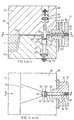
- Fig. 1 einen Längsschnitt gemäss Linie A-B in Fig. durch die Kombination aus Mischer und Formwerkzeug gemäss einem ersten Ausführungsbeispiel in der Darstellung während des Formfüllvorganges,
- Fig.2 eine Draufsicht bzw. einen Schnitt gemäss Linie C-D in Fig. 1,
- Fig. 3 die Kombination aus Mischer und Formwerkzeug gemäss Fig. 1 in der Darstellung des Entformungsvorganges,
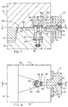
- Fig. 4 einen Längsschnitt gemäss Linie E-F in Fig. durch die Kombination aus Mischer und Formwerkzeug gemäss einem zweiten Ausführungsbeispiel in Darstellung während des Formfüllvorganges,
- Fig. eine Draufsicht bzw. einen Schnitt gemäss Linie G-H in Fig. 4,
- Fig. die Kombination aus Mischer und Formwerkzeug gemäss Fig.4 in der Darstellung während des Entformungsvorganges,
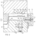
- Fig.7 einen Längsschnitt gemäss Linie I-K in Fig.8 durch die Kombination aus Mischer und Formwerkzeug gemäss einem dritten Ausführungsbeispiel in Darstellung während des Formfüllvorganges,
- Fig.8 eine Draufsicht bzw. einen Schnitt gemäss Linie L-M in Fig. 7 und
- Fig. 9 die Kombination aus Mischer und Formwerkzeug gemäss Fig. 7 in der Darstellung während des Entformungsvorganges.
- 1 shows a longitudinal section along line AB in FIG. 1 through the combination of mixer and molding tool according to a first exemplary embodiment in the illustration during the mold filling process,
- 2 shows a plan view or a section along line CD in FIG. 1,
- 3 shows the combination of mixer and molding tool according to FIG. 1 in the representation of the demolding process,
- 4 shows a longitudinal section along line EF in FIG. 1 through the combination of mixer and molding tool according to a second exemplary embodiment, shown during the mold filling process,
- FIG. 4 shows a top view or a section along line GH in FIG. 4, FIG.
- 4 shows the combination of mixer and molding tool according to FIG. 4 during the demolding process,
- 7 shows a longitudinal section along line IK in FIG. 8 through the combination of mixer and molding tool according to a third exemplary embodiment, shown during the mold filling process,
- 8 is a plan view or a section along line LM in Fig. 7 and
- FIG. 9 shows the combination of mixer and molding tool according to FIG. 7 in the illustration during the demolding process.
In Fig. 1 bis 3 besteht die Kombination aus einem angebauten Mischer 1 und einem Formwerkzeug 2. Der Mischer 1 umfasst ein Gehäuse 3 mit einer Mischkammer 4, in welche Einspritzdüsen 5, 6 für die Reaktionskomponenten einmünden, sowie einen Ausstosskolben 7. Der Mischer 1 ist an der unteren Formwerkzeughälfte 8 befestigt. Zwischen der unteren Formwerkzeughälfte 8 und der oberen Formwerkzeughälfte 9 verläuft die Formtrennebene 10 und ein von der Mischkammer 4 bis zu einem Formhohlraum 11 reichender Angusskanal 12. Er ist im wesentlichen in die untere Formwerkzeughälfte 8 eingebettet und wird von der Formtrennebene 10 tangiert. Der Angusskanal 12 verengt sich von der Mischkammer 4 zu einem Drosselspalt 13 hin. Dieser ist durch einen einstellbaren Schieber 14 und eine Gegenfläche 15 gebildet. Die Gegenfläche 15 ist Teil eines in die obere Formwerkzeughälfte 9 eingepassten Einsatzstückes 16, welches zum Angusskanal 12 hin die Kontur einer Kugelkalotte 17 aufweist. Dadurch ist hinter dem Drosselspalt 13 eine aus dem Volumen der Kugelkalotte 17 und dem Volumen des in diesem Bereich gelegenen Abschnittes des Angusskanals 12 bestehende Beruhigungskammer 18 gebildet. An sie schliesst sich der sich erweiternde und gleichzeitig verflachende Abschnitt 19 des Angusskanals 12 an. Die Kreisumfangslinie 20 der Kugelkalotte 17 und die Kreisumfangslinie 21 des Schiebers 14 überschneiden sich an ihrer zur Mischkammer 4 hin gelegenen Seite und bilden somit einen Drosselspalt 13 unterschiedlicher Länge. Der Schieber 14 ist als beidseitig beaufschlagbarer, in einer Hydraulikkammer 22 geführter Hydraulikkolben 23 gestaltet, welcher zum Einstellen der Hubweite und damit der Höhe des Drosselspaltes 13 mit einer verstellbaren Anschlagschraube 24 versehen ist. Nach dem Aushärten des Formteils und Öffnen des Formwerkzeuges 2 lässt sich das Formteil zusammen mit der Angussstange 25 entfernen.1 to 3, the combination consists of an attached
Auch in Fig. 4 bis 6 besteht die Kombination aus einem angebauten Mischer 31 und einem Formwerkzeug 32. Der Mischer 31 umfasst ein Gehäuse 33 mit einer Mischkammer 34, in welche Einspritzdüsen 35, 36 für die Reaktionskomponenten münden, sowie einen Ausstosskolben 37. Der Mischer 31 ist an der unteren Formwerkzeughälfte 38 befestigt. Zwischen der unteren Formwerkzeughälfte 38 und der oberen Formwerkzeughälfte 39 verläuft die Formtrennebene 40. Ein sich von der Mischkammer 34 bis zu einem Formhohlraum 41 erstreckender Angusskanal 42 ist im wesentlichen in die untere Formwerkzeughälfte 38 eingebettet und wird von der Formtrennebene 40 tangiert. Der Angusskanal 42 verengt sich von der Mischkammer 34 zu einem Drosselspalt 43 hin. Dieser ist durch einen einstellbaren, als Schieber 44 ausgebildeten Zapfen und eine Gegenfläche 45 gebildet, welche aus der Stirnfläche eines zweiten Schiebers 46 besteht. Der Schieber 46 bildet den Boden 45 einer Vertiefung 47, in welche der Schieber 44 hineinragt. Der Schieber 44 besitzt rechteckigen Querschnitt. Er ist mit einem Hydraulikkolben 48, welcher in einer Hydraulikkammer 49 geführt ist, versehen. Mittels einer Anschlagschraube 50 lässt sich die Hubweite einstellen. Der Schieber 44 bildet zwischen sich und dem der Mischkammer 34 zugewandten Wandungsteil 52 der Vertiefung 47 einen dem eigentlichen Drosselspalt 43 vorgeordneten Spalt 51 kleineren Querschnittes. Der Spalt 51 ist unveränderlich. Je nach Einstellung der Schieber 44 bis 46 ist jedoch seine Länge variabel. Der Schieber 44 ist an die seitlichen Wandungsteile 53 der Vertiefung 57 abdichtend angepasst. Zwischen dem Schieber 44 und dem zum Formhohlraum 41 weisenden Wandungsteil 54 erstreckt sich eine Beruhigungskammer 55. Ihr Volumen ist durch die Verstellung des Schiebers 46 einstellbar. Hierzu ist der Schieber 46 ebenfalls mit einem in einer Hydraulikkammer 56 geführten Ausstosskolben 57 und einer einstellbaren Anschlagschraube 58 versehen. An die Beruhigungskammer 55 schliesst der sich erweiternde und gleichzeitig verflachende Abschnitt 59 des Angusskanals 42 an. Einer der Schieber 44 und 46 lässt sich zusätzlich als Auswerfer ausbilden, wozu eine entsprechende Steuerung vozusehen ist. Dadurch lässt sich nach dem Öffnen des Formwerkzeugs 32 das Entformen der Angusstange 60 erleichtern.4 to 6 there is also the combination of an attached
In Fig. bis 9 besteht die Kombination aus einem Mischer 71 und einem Formwerkzeug 72, wobei der Mischer 71 an das Formwerkzeug 72 angebaut ist. Der Mischer 71 umfasst ein Gehäuse 73 mit einer Mischkammer 74, in welche Einspritzdüsen 75, 76 für die Reaktionskomponenten münden, sowie einen Ausstosskolben 77. Der Mischer 71 ist an der unteren Formwerkzeughälfte 78 befestigt. Zwischen der unteren Formwerkzeughälte 78 und der oberen Formwerkzeughälfte 79 verläuft die Formtrennebene 80. Ein sich von der Mischkammer 74 bis zu einem Formhohlraum 81 erstreckender Angusskanal 82 ist im wesentlichen in die untere Formwerkzeughälfte 78 eingebettet und wird von der Formtrennebene 80 tangiert. Der Angusskanal 82 verengt sich von der Mischkammer 74 zu einem Drosselspalt 83 hin. Dieser ist durch einen als Schieber 84 ausgebildeten Zapfen mit halbkreisförmigem Querschnitt und einer Gegenfläche 85, welche den Boden einer Vertiefung 86 darstellt, gebildet. Die Vertiefung 86 ist in der oberen Formwerkzeughälfte 79 angeordnet. Der Schieber 84 bildet mit dem zur Mischkammer 74 hin gelegenen Wandungsteil 87 der Vertiefung 86 einen dem eigentlichen Drosselspalt 83 vorgeordneten fixen Spalt 88. Zwischen der Rückseite des Schiebers 84 und dem zum Formhohlraum 81 hin gelegenen Wandungsteil 89 der Vertiefung 86 erstreckt sich eine Beruhigungskammer 90. Diese mündet über den Angusskanal 82 in eine zweite Vertiefung 91, in welche ebenfalls ein als Schieber 92 ausgebildeter Zapfen einfahrbar ist, welcher mit einer den Boden der Vertiefung 91 bildenden Gegenfläche 93 einen zweiten einstellbaren Drosselspalt 94 bildet. Auch hier ist dem Drosselspalt 94 ein fixer Spalt 95 vorgelagert. Hinter dem Schieber 92 ist eine zweite Beruhigungskammer 96 angeordnet. Der Drosselspalt 94 besitzt grösseren Querschnitt als der Drosselspalt 83, und die zweite Beruhigungskammer 96 weist grösseres Volumen auf als die Beruhigungskammer 90. Der Schieber 92 ist ebenfalls mit einem grösseren Querschnitt ausgestattet als der Schieber 84. Der Angusskanal 82 erweitert sich bereits vom Bereich des Schiebers 84 an hinter der Beruhigungskammer 96 bis zum Formhohlraum 81 hin. Die beiden Schieber 84 und 92 sind auf einem gemeinsamen, in einer Hydraulikkammer 97 geführten Hydraulikkolben 98 angeordnet, welcher mit einer Anschlagschraube 99 versehen ist. Die Hubweite der Schieber 84 und 92 ist bei dieser Ausführungsform also nur gemeinsam einstellbar. Die Schieber 84 und 92 können aber unterschiedlich lang gestaltet sein, so dass die Drosselspalte 83 und 94 verschiedene Höhe haben. Es versteht sich, dass die Schieber 84 und 92 auch getrennte hydraulische Antriebe besitzen können und damit einzeln einstellbar sind. Zwischen der Beruhigungskammer 90 und dem Schieber 92 erstreckt sich ein Abschnitt 100 des Angusskanals 82 und zwischen der Beruhigungskammer 96 und dem Formhohlraum 81 der Abschnitt 101. Die im Angusskanal 82 verbleibende Angussstange ist mit 102 bezeichnet.9 to 9, the combination consists of a
Claims (11)
Applications Claiming Priority (2)
| Application Number | Priority Date | Filing Date | Title |
|---|---|---|---|
| DE19853500235 DE3500235A1 (en) | 1985-01-05 | 1985-01-05 | COMBINATION OF MIXER AND MOLDING TOOL FOR PRODUCING MOLDED PARTS FROM A FLOWABLE REACTION MIXTURE FROM AT LEAST TWO FLOWABLE REACTION COMPONENTS |
| DE3500235 | 1985-01-05 |
Publications (3)
| Publication Number | Publication Date |
|---|---|
| EP0187360A2 EP0187360A2 (en) | 1986-07-16 |
| EP0187360A3 EP0187360A3 (en) | 1987-06-03 |
| EP0187360B1 true EP0187360B1 (en) | 1989-07-05 |
Family
ID=6259319
Family Applications (1)
| Application Number | Title | Priority Date | Filing Date |
|---|---|---|---|
| EP85116410A Expired EP0187360B1 (en) | 1985-01-05 | 1985-12-21 | Mixer mould combination for producing articles from a fluidic reactive mixture of at least two fluidic reactive components |
Country Status (3)
| Country | Link |
|---|---|
| US (1) | US4680003A (en) |
| EP (1) | EP0187360B1 (en) |
| DE (2) | DE3500235A1 (en) |
Families Citing this family (15)
| Publication number | Priority date | Publication date | Assignee | Title |
|---|---|---|---|---|
| DE3613076A1 (en) * | 1986-04-18 | 1987-10-29 | Bayer Ag | Process and device for producing solid or foamed mouldings from a flowable reaction mixture |
| JPH0337931Y2 (en) * | 1986-04-30 | 1991-08-12 | ||
| US4840556A (en) * | 1987-07-16 | 1989-06-20 | Extrusion Punch & Tool Co. | Mixing plate for injection molding machine |
| DE3736022A1 (en) * | 1987-10-24 | 1989-05-03 | Hennecke Gmbh Maschf | DEVICE FOR PRODUCING MOLDED PARTS FROM A PLASTIC, IN PARTICULAR FOAM PLASTIC, REACTIVE, FLOWABLE REACTION MIXTURE FROM FLOWABLE REACTION COMPONENTS |
| US5133921A (en) * | 1987-12-31 | 1992-07-28 | Sanken Electric Co., Ltd. | Method for manufacturing plastic encapsulated electronic semiconductor devices |
| US5049055A (en) * | 1987-12-31 | 1991-09-17 | Sanken Electric Co., Ltd. | Mold assembly |
| US5101882A (en) * | 1990-03-14 | 1992-04-07 | Chrysler Corporation | Die cast vacuum valve system |
| US5498151A (en) * | 1993-05-05 | 1996-03-12 | Nennecker; Gunter H. | Mixing head for molding machine |
| US5586596A (en) * | 1994-09-26 | 1996-12-24 | Freeman; Lewis G. | Die cast vent block |
| US5540272A (en) * | 1994-09-26 | 1996-07-30 | Freeman; Lewis G. | Die cast vacuum valve |
| US5536286A (en) * | 1994-09-26 | 1996-07-16 | Freeman; Lewis G. | Vacuum valve filtering system |
| US5538069A (en) * | 1994-09-26 | 1996-07-23 | Freeman; Lewis G. | Die cast vacuum valve |
| US7976298B2 (en) * | 2003-12-23 | 2011-07-12 | Magna International Inc. | Article, method and apparatus of forming expanded plastic materials in a steam chest mold |
| TW201233521A (en) * | 2011-02-01 | 2012-08-16 | Quanta Comp Inc | Plastic material injection molding system |
| CN110893692B (en) | 2018-09-13 | 2022-05-24 | 德斯马制鞋设备有限公司 | Injection molding system with pressure dependent valve |
Family Cites Families (15)
| Publication number | Priority date | Publication date | Assignee | Title |
|---|---|---|---|---|
| US2313004A (en) * | 1939-10-02 | 1943-03-02 | Pritchard Percy | Casting of metals |
| CH512987A (en) * | 1969-09-04 | 1971-09-30 | Buehler Ag Geb | Method and device for the injection molding of plastic into foamed objects |
| US3819313A (en) * | 1970-04-02 | 1974-06-25 | Allied Chem | Apparatus for molding articles |
| DE2252201A1 (en) * | 1972-10-25 | 1974-05-22 | 5090 Leverkusen | DEVICE FOR MANUFACTURING MOLDED PARTS FROM FAST-REACTING CHEMICAL COMPONENTS |
| AT351243B (en) * | 1973-09-14 | 1979-07-10 | Demag Kunststofftech | GATE DEVICE FOR CASTING FORMS FOR THE PRODUCTION OF OBJECTS FROM PLASTICS FORMING FROM MULTIPLE LIQUID COMPONENTS |
| DE2348608C3 (en) * | 1973-09-27 | 1980-09-18 | Bayer Ag, 5090 Leverkusen | Device for the production of foamed or homogeneous substances from flowable reaction components |
| US3897929A (en) * | 1974-08-12 | 1975-08-05 | Nat Tool And Manufacturing Co | Recessed sprue bushing for a three-plate mold set |
| US4067673A (en) * | 1975-09-02 | 1978-01-10 | Ex-Cell-O Corporation | Apparatus for injection foam molding |
| DE2612812C3 (en) * | 1976-03-25 | 1983-05-26 | Bayer Ag, 5090 Leverkusen | Mixing head for mixing at least two components which form foam when they react |
| DE2737616A1 (en) * | 1977-08-20 | 1979-03-01 | Bayer Ag | METHOD AND DEVICE FOR PRODUCING A FOAM- OR HOMOGENIC MATERIAL-FORMING REACTION MIXTURE AND FOR ITS SUBSEQUENT ENTRY INTO A CAVITY |
| DE2934354A1 (en) * | 1979-08-24 | 1981-03-26 | Bayer Ag, 51373 Leverkusen | METHOD FOR FILLING CAVES, ESPECIALLY SUCH MOLDING TOOLS, WITH A REACTIVE, FLOWABLE MIXTURE |
| US4446088A (en) * | 1981-09-08 | 1984-05-01 | Mobil Oil Corporation | Method and mold for making an improved egg carton |
| DE3216647A1 (en) * | 1982-05-04 | 1983-11-10 | Elastogran Maschinenbau GmbH, 2844 Lemförde | MIXING DEVICE FOR MULTI-COMPONENT PLASTICS |
| DE3341308A1 (en) * | 1982-11-16 | 1984-05-17 | Basf Ag, 6700 Ludwigshafen | Post-mixer integrated into the feed channel for split casting moulds |
| EP0135798B1 (en) * | 1983-09-03 | 1989-03-15 | MASCHINENFABRIK HENNECKE GmbH | Multiple nozzle bringing together at least two free-flowing reactants for the preparation of a free-flowing reaction mixture which reacts into plastic, in particular into foamed plastic |
-
1985
- 1985-01-05 DE DE19853500235 patent/DE3500235A1/en not_active Withdrawn
- 1985-12-20 US US06/811,254 patent/US4680003A/en not_active Expired - Fee Related
- 1985-12-21 DE DE8585116410T patent/DE3571310D1/en not_active Expired
- 1985-12-21 EP EP85116410A patent/EP0187360B1/en not_active Expired
Also Published As
| Publication number | Publication date |
|---|---|
| US4680003A (en) | 1987-07-14 |
| EP0187360A2 (en) | 1986-07-16 |
| DE3571310D1 (en) | 1989-08-10 |
| DE3500235A1 (en) | 1986-07-10 |
| EP0187360A3 (en) | 1987-06-03 |
Similar Documents
| Publication | Publication Date | Title |
|---|---|---|
| EP0187360B1 (en) | Mixer mould combination for producing articles from a fluidic reactive mixture of at least two fluidic reactive components | |
| EP0137250B1 (en) | Multiple nozzle for bringing together at least two free-flowing reactants forming plastic, in particular foamed plastic, in order to start the reaction by mixing, and method of operating said multiple nozzle | |
| EP0024608B2 (en) | Method and device for produding mouldings using a free-flowing reaction mixture forming a solid or foamed material | |
| DE2513492C3 (en) | Device for mixing a liquid propellant with a low boiling point with other components for the production of foam | |
| EP0261350B1 (en) | Apparatus for manufacturing moulded plastics | |
| EP0024610B1 (en) | Method of filling cavities of forming devices, with a reactive mixture of at least two liquid reaction components forming a solid plastics material | |
| DE2342794B2 (en) | Method and device for the discontinuous production of multilayer molded parts from thermoplastic material | |
| EP0099045B1 (en) | Method and mixer head for the production of a reactable mixture of at least two flowable reactable components for plastics material | |
| DE2346135A1 (en) | METHOD AND DEVICE FOR THE DISCONTINUOUS MANUFACTURING OF MULTI-LAYER MOLDED PARTS FROM THERMOPLASTIC PLASTIC | |
| EP0310914A2 (en) | Method of injection moulding formed parts of thermoplastic resins, and for carrying out this method | |
| DE60209505T3 (en) | METHOD FOR INJECTION MOLDING | |
| DE3014175A1 (en) | METHOD AND DEVICE FOR INJECTION MIXING AND DISPENSING FOR HIGH-SPEED REACTIONS | |
| EP0260564B1 (en) | Method and device for continuously making a plastic material, essentially a liquid reactive mixture for making foam, from at least two liquid components | |
| EP0070486B1 (en) | Method and apparatus for the production of a reaction mixture capable to flow of at least two reaction components reacting together for making homogeneous or foamed material | |
| EP0084672B1 (en) | Apparatus for producing a chemically reactive mixture of at least two plastics material components | |
| DE10136243B4 (en) | Valve arrangement for controlling the metered addition of fluid additives into a plastic melt | |
| DE2623308B2 (en) | Device for the discontinuous production of molded parts from thermoplastic material | |
| DE3521236A1 (en) | MIXING HEAD FOR MIXING AT LEAST TWO PLASTIC COMPONENTS | |
| EP0088936B1 (en) | Mixing head for producing a preferably chemically reactive mixture from at least two synthetic resin components | |
| DE19819833A1 (en) | Method and device for injecting plastic material | |
| DE102007045439B3 (en) | Melt mixer or filter unit mounted in injection molding machine nozzle is cylindrical and has central blind bore terminating in channel at downstream end which is closed by ball valve during injection, valve opening when screw is withdrawn | |
| DE4009465C2 (en) | DEVICE FOR MIXING AT LEAST TWO REACTIVE PLASTIC COMPONENTS | |
| DE4216393C2 (en) | Post-mixer for RIM technology molds | |
| EP0564908A1 (en) | Device for mixing interreacting reactive components | |
| EP0070487B1 (en) | Apparatus for the production of a reaction mixture capable to flow of at least two reaction components reacting together for making homogeneous or foamed material |
Legal Events
| Date | Code | Title | Description |
|---|---|---|---|
| PUAI | Public reference made under article 153(3) epc to a published international application that has entered the european phase |
Free format text: ORIGINAL CODE: 0009012 |
|
| 17P | Request for examination filed |
Effective date: 19851221 |
|
| AK | Designated contracting states |
Kind code of ref document: A2 Designated state(s): DE FR GB IT |
|
| PUAL | Search report despatched |
Free format text: ORIGINAL CODE: 0009013 |
|
| AK | Designated contracting states |
Kind code of ref document: A3 Designated state(s): DE FR GB IT |
|
| 17Q | First examination report despatched |
Effective date: 19871210 |
|
| GRAA | (expected) grant |
Free format text: ORIGINAL CODE: 0009210 |
|
| AK | Designated contracting states |
Kind code of ref document: B1 Designated state(s): DE FR GB IT |
|
| ITF | It: translation for a ep patent filed |
Owner name: ING. C. GREGORJ S.P.A. |
|
| GBT | Gb: translation of ep patent filed (gb section 77(6)(a)/1977) | ||
| REF | Corresponds to: |
Ref document number: 3571310 Country of ref document: DE Date of ref document: 19890810 |
|
| ET | Fr: translation filed | ||
| PLBE | No opposition filed within time limit |
Free format text: ORIGINAL CODE: 0009261 |
|
| STAA | Information on the status of an ep patent application or granted ep patent |
Free format text: STATUS: NO OPPOSITION FILED WITHIN TIME LIMIT |
|
| 26N | No opposition filed | ||
| ITTA | It: last paid annual fee | ||
| PGFP | Annual fee paid to national office [announced via postgrant information from national office to epo] |
Ref country code: DE Payment date: 19951114 Year of fee payment: 11 |
|
| PGFP | Annual fee paid to national office [announced via postgrant information from national office to epo] |
Ref country code: FR Payment date: 19951129 Year of fee payment: 11 |
|
| PGFP | Annual fee paid to national office [announced via postgrant information from national office to epo] |
Ref country code: GB Payment date: 19951212 Year of fee payment: 11 |
|
| PG25 | Lapsed in a contracting state [announced via postgrant information from national office to epo] |
Ref country code: GB Effective date: 19961221 |
|
| GBPC | Gb: european patent ceased through non-payment of renewal fee |
Effective date: 19961221 |
|
| PG25 | Lapsed in a contracting state [announced via postgrant information from national office to epo] |
Ref country code: FR Effective date: 19970829 |
|
| PG25 | Lapsed in a contracting state [announced via postgrant information from national office to epo] |
Ref country code: DE Effective date: 19970902 |
|
| REG | Reference to a national code |
Ref country code: FR Ref legal event code: ST |