EP0260564B1 - Method and device for continuously making a plastic material, essentially a liquid reactive mixture for making foam, from at least two liquid components - Google Patents
Method and device for continuously making a plastic material, essentially a liquid reactive mixture for making foam, from at least two liquid components Download PDFInfo
- Publication number
- EP0260564B1 EP0260564B1 EP87113036A EP87113036A EP0260564B1 EP 0260564 B1 EP0260564 B1 EP 0260564B1 EP 87113036 A EP87113036 A EP 87113036A EP 87113036 A EP87113036 A EP 87113036A EP 0260564 B1 EP0260564 B1 EP 0260564B1
- Authority
- EP
- European Patent Office
- Prior art keywords
- mixing chamber
- rebound
- mixing
- deflection
- insert
- Prior art date
- Legal status (The legal status is an assumption and is not a legal conclusion. Google has not performed a legal analysis and makes no representation as to the accuracy of the status listed.)
- Expired - Lifetime
Links
Images


Classifications
-
- B—PERFORMING OPERATIONS; TRANSPORTING
- B29—WORKING OF PLASTICS; WORKING OF SUBSTANCES IN A PLASTIC STATE IN GENERAL
- B29B—PREPARATION OR PRETREATMENT OF THE MATERIAL TO BE SHAPED; MAKING GRANULES OR PREFORMS; RECOVERY OF PLASTICS OR OTHER CONSTITUENTS OF WASTE MATERIAL CONTAINING PLASTICS
- B29B7/00—Mixing; Kneading
- B29B7/74—Mixing; Kneading using other mixers or combinations of mixers, e.g. of dissimilar mixers ; Plant
- B29B7/76—Mixers with stream-impingement mixing head
- B29B7/7615—Mixers with stream-impingement mixing head characterised by arrangements for controlling, measuring or regulating, e.g. for feeding or proportioning the components
-
- B—PERFORMING OPERATIONS; TRANSPORTING
- B29—WORKING OF PLASTICS; WORKING OF SUBSTANCES IN A PLASTIC STATE IN GENERAL
- B29B—PREPARATION OR PRETREATMENT OF THE MATERIAL TO BE SHAPED; MAKING GRANULES OR PREFORMS; RECOVERY OF PLASTICS OR OTHER CONSTITUENTS OF WASTE MATERIAL CONTAINING PLASTICS
- B29B7/00—Mixing; Kneading
- B29B7/74—Mixing; Kneading using other mixers or combinations of mixers, e.g. of dissimilar mixers ; Plant
- B29B7/76—Mixers with stream-impingement mixing head
- B29B7/7663—Mixers with stream-impingement mixing head the mixing head having an outlet tube with a reciprocating plunger, e.g. with the jets impinging in the tube
- B29B7/7684—Parts; Accessories
-
- B—PERFORMING OPERATIONS; TRANSPORTING
- B29—WORKING OF PLASTICS; WORKING OF SUBSTANCES IN A PLASTIC STATE IN GENERAL
- B29B—PREPARATION OR PRETREATMENT OF THE MATERIAL TO BE SHAPED; MAKING GRANULES OR PREFORMS; RECOVERY OF PLASTICS OR OTHER CONSTITUENTS OF WASTE MATERIAL CONTAINING PLASTICS
- B29B7/00—Mixing; Kneading
- B29B7/74—Mixing; Kneading using other mixers or combinations of mixers, e.g. of dissimilar mixers ; Plant
- B29B7/76—Mixers with stream-impingement mixing head
- B29B7/7631—Parts; Accessories
- B29B7/7636—Construction of the feed orifices, bores, ports
-
- B—PERFORMING OPERATIONS; TRANSPORTING
- B29—WORKING OF PLASTICS; WORKING OF SUBSTANCES IN A PLASTIC STATE IN GENERAL
- B29B—PREPARATION OR PRETREATMENT OF THE MATERIAL TO BE SHAPED; MAKING GRANULES OR PREFORMS; RECOVERY OF PLASTICS OR OTHER CONSTITUENTS OF WASTE MATERIAL CONTAINING PLASTICS
- B29B7/00—Mixing; Kneading
- B29B7/74—Mixing; Kneading using other mixers or combinations of mixers, e.g. of dissimilar mixers ; Plant
- B29B7/76—Mixers with stream-impingement mixing head
- B29B7/7663—Mixers with stream-impingement mixing head the mixing head having an outlet tube with a reciprocating plunger, e.g. with the jets impinging in the tube
Definitions
- the invention relates to a method and a device for producing a plastic, in particular foam-forming, flowable reaction mixture from at least two flowable reaction components, the reaction components being injected in a metered manner through a nozzle opening into a mixing zone from which the resulting reaction mixture is discharged and which is subsequently cleaned .
- a method and such a device are known from FR-A-2 299 578.
- the method described at the beginning belongs to the different variants of the so-called RIM technique (reaction injection molding), the components being injected into a mixing zone by means of perforated nozzles or needle valve nozzles to ensure sufficient mixing with high injection pressures.
- Good mixing becomes more difficult the higher the viscosity of the components.
- the injection pressures have therefore been raised to over 200 bar in order to achieve a beam expansion and a fine droplet distribution. However, this increases the load on the metering pumps and there is a risk of hose lines bursting.
- nozzle openings must be kept extremely small, which causes blockages in filler-containing components. Attempts have therefore already been made to overcome these disadvantages by heating the components in order to reduce the viscosity. However, this means that some components have to accept reduced shelf life and the required energy consumption, as well as increased reactivity if necessary.
- post-mixing you can achieve a gradual improvement in the quality of the mix, but no solution to the pre-run and post-run problems. In the case of post-mixing, there is also a loss of material and there are cleaning problems when processing so-called self-separating systems.
- This object is achieved in that at least one of the component jets after passing through the nozzle opening, but before entering the mixing zone, is deflected and thereby expanded.
- the component jet impinges against a deflection surface almost immediately after it emerges from the nozzle opening, which generally represents the narrowest nozzle cross section, and partially penetrates itself due to the setting angle of this deflection surface, which promotes the formation of particularly fine drops.
- the component beam already widens somewhat and this widening continues on its way into the mixing chamber. It is understood that the degree of expansion depends on the injection pressure, the viscosity of the component, the angle of incidence and the contour of the deflection surface. Of course, it is particularly advantageous if all the component beams supplied are deflected. It may well be useful for the deflection to take place under different conditions, such as different angles.
- the jet is preferably deflected obliquely against the outflow direction from the mixing zone.
- the beam is guided over a tear-off edge after deflection.
- the new process can be used particularly advantageously for self-cleaning mixing zones.
- the device for making an art Material, in particular foam-forming flowable reaction mixture of at least two flowable, metered feed reaction components in the pass starts from storage containers for the reaction components, from which feed lines via metering pumps lead to nozzle openings which point into the mixing chamber of a mixing head, the mixing chamber having an outlet opening and optionally one Ejection piston has.
- baffle or deflection surface is arranged between at least one of the nozzle openings and the mixing chamber.
- the deflecting surface acts more as a sliding surface or more as an impact surface. This depends on the setting angle of the deflecting surface and on whether the deflecting surface attaches directly to the nozzle opening or whether it is at a distance from it. Depending on the properties of the component to be injected, in particular its viscosity, the choice in one direction or the other is of greater advantage. It goes without saying that a deflecting surface is preferably assigned to each nozzle opening, each of which can have its particular configuration according to the requirements of the reaction components.
- the baffle or deflection surface preferably rises in the opposite direction to the outlet opening of the mixing chamber.
- the baffle or deflecting surface has a tear-off edge towards the mixing chamber.
- This tear-off edge is preferably arranged transversely to the mixing chamber axis. If it is a mixing head with ejection and control pistons, there is the particular advantage that the effective closing and opening processes of the inlet openings into the mixing chamber through the ejection piston run extremely cheaply because the deflected jet is particularly flat when entering the mixing chamber and is therefore suddenly released or interrupted. It is understood that the ejection piston can also be designed as a control piston in a manner known per se. If there is no discharge piston, the mixing chamber must be rinsed.
- the impact or deflection surface has a contour.
- contouring a convex or concave curvature; an open channel-like formation, which tapers or widens towards the mixing chamber; fine grooves which are arranged lengthways, crossways or obliquely on the deflection surface; tiny bumps formed by intersecting grooves.
- one or the other type of contouring, or combinations thereof is advantageous.
- the baffle or deflecting surface is arranged directly in the nozzle body of an injection nozzle.
- this embodiment has the advantage that it is a single piece; it is disadvantageous, however, that if a differently designed deflection surface or a different distance of the deflection surface from the nozzle opening is required, the entire unit must be replaced.
- the baffle or deflection surface is therefore arranged in an insert.
- This embodiment has the advantage that only the insert needs to be replaced using the same injector.
- Another special embodiment is characterized by a common insert for all baffle or deflecting surfaces, this insert containing the mixing chamber.
- the insert preferably has recesses in which the injection nozzles are interchangeably arranged.
- a common insert has the particular advantage that due to the fixed position of all critical distances from each other, special adjustment work is not necessary. In particular, this prevents pre-run and post-run problems when opening and closing the insert openings by means of an ejection and control piston.
- This embodiment offers the further particular advantage that the distance of the baffle or deflecting surface from the nozzle opening is adjustable.
- This adjustability can be accomplished in a simple manner by inserting spacer rings of appropriate thickness between the injection nozzle and the insert.
- the injection nozzle can also be supported in a ball or a spherical segment, so that the angle between the axis of the injection nozzle and the deflection surface can be adjusted.
- This embodiment is also extremely complex and should only be considered for very special cases.
- the baffle or deflection surface is assigned a counter surface, which together form a defined inlet gap towards the mixing chamber.
- this inlet gap one has a larger cross-section than this nozzle opening.
- supply lines 3, 4 lead from a storage container 1 for polyol and a storage container 2 for isocyanate via metering pumps 5, 6 to the mixing chamber 7 of a mixing head 8 indicated schematically in construction. They lead to injection nozzles 11, 12 provided with nozzle openings 9, 10. The nozzle openings 9, 10 point into the mixing chamber 7 through the actual inlet openings 14, 15 arranged in the wall 13 of the mixing chamber 7.
- the mixing chamber 7 is part of a guide bore 16 in which an ejection piston 17 is guided, which is pushed forward after the mixing process, thereby ejecting the remaining mixture in the mixing chamber 7 and filling the mixing chamber 7 up to the outlet opening 18.
- the mixing head 8 is shown enlarged in various exemplary embodiments.
- the mixing head 25 consists of a housing 26 in which a guide bore 27 for an ejection piston 28 is arranged. In the position shown, the ejection piston 28 releases a mixing chamber 29 and the inlet openings 31, 32 arranged in the wall 30 of the mixing chamber 29. Feed lines (not shown) for the reaction components open into injection nozzles 33, 34 which are arranged in housing bores 35, 36 and have nozzle openings 37, 38.
- an insert 39 is arranged secured against rotation. It has a channel 40, the bottom of which is designed as a flat deflection surface 41. This deflecting surface 41 begins at the lower edge of the nozzle opening 37 and rises at an angle of 10 ° to the axis of the injection nozzle 33, so that the emerging mixture jet essentially slides along the deflecting surface 41.
- the insert 39 is adapted to the mixing chamber 29 towards the wall 30 thereof. In this case, the end of the deflecting surface 41 which is located towards the mixing chamber 29 forms a sharp tear-off edge 42 which is oriented transversely to the axis of the mixing chamber 29.
- the injection nozzle 34 consists of a nozzle body 43, which is extended beyond the nozzle opening 38.
- a channel 44 is arranged within this extension, the bottom of which is also designed as a deflection surface 45.
- This deflection surface 45 begins about 1 mm below the nozzle opening 38, so that the jet emerging from it impinges obliquely on the deflection surface 45 set at an angle of 10 ° and is deflected upwards.
- the deflection surface 45 ends toward the mixing chamber 29 with a sharp tear-off edge 46, which is part of the boundary of the inlet opening 32.
- the mixing head 51 consists of a housing 52 in which a guide bore 53 for an ejection piston 54 is arranged. In the position shown, the ejection piston 54 releases the mixing chamber 55 and the inlet opening 57 arranged in the wall 56 of the mixing chamber 55.
- a feed line (not shown) leads.
- the injection nozzle 58 is arranged in a housing bore 59.
- An insert 60 is provided between the injection nozzle 58 and the mixing chamber 55 and has a channel 61, the bottom of which is designed as a deflection surface 62.
- This deflection surface 62 begins somewhat below the nozzle opening 63, is trough-shaped and runs flat upwards to the mixing chamber wall 56 or to the inlet opening 57 and forms a sharp tear-off edge 64 there. This is aligned transversely to the axis of the mixing chamber 55.
- the surface of the deflection surface 62 has a contour 65 in the form of transverse grooves 0.3 mm deep.
- the mixing head 71 consists of a housing 72 in which a guide bore 73 for an ejection piston 74 is arranged. In the position shown, the ejection piston 74 releases the mixing chamber 75 and the inlet opening 77 arranged in the wall 76 of the mixing chamber 75.
- a feed line (not shown) leads.
- the injection nozzle 78 is arranged in a housing bore 79.
- a perforated spacer 80 and an insert 81 are secured against rotation between the injection nozzle 78 and the mixing chamber 75.
- the latter has a channel 82 rising obliquely upwards, the bottom of which is designed as a deflection surface 83. This deflecting surface 83 begins somewhat below the nozzle opening 85, is convexly curved and ends in a tear-off edge 84 in the inlet opening 77.
- the mixing head 91 consists of a housing 92, in which a guide bore 93 for an ejection piston 94 is arranged. In the In the position shown, the discharge piston 94 releases the mixing chamber 95 and the inlet opening 97 arranged in the wall 96.
- the injector 98 is shown. A nozzle of the same design would be a mirror image in the same axis.
- a feed line (not shown) leads to the injection nozzle 98.
- the injection nozzle 98 consists of the actual nozzle body 99 and a perforated diaphragm 100 with a nozzle opening 101.
- a spacer 102 and an insert 103 are arranged between the perforated diaphragm 100 and the mixing chamber 95.
- This insert 103 is provided with a pin 104 which engages in a groove 105 and in this way prevents the insert 103 from rotating. All of these parts are arranged in a housing bore 106.
- the insert piece 103 has a channel 107, the bottom of which is designed as a deflection surface 108.
- This deflection surface 108 begins at the lower edge of the hole 109 in the spacer 102 and is thus positioned lower than the lower edge of the nozzle opening 101.
- the deflection surface 108 rises upwards to the mixing chamber 95, wherein it has a kink 110, behind which it rises even more.
- the inlet opening 97 here has the shape of a narrow inlet gap which extends transversely to the axis of the mixing chamber 95. Its lower edge is also designed as a tear-off edge 111.
- the mixing head 121 consists of a housing 122 in which a guide bore 123 for an ejection piston 124 is arranged. In the position shown, the ejection piston 124 releases the mixing chamber 125 and the inlet opening 127 arranged in the wall 126 of the mixing chamber 125.
- the injection nozzle 128 consists of a nozzle body 129 and a perforated diaphragm, which forms a unit with an insert 130.
- This insert piece 130 has a nozzle opening 131, to which a channel 132 connects, which leads to the inlet opening 127. Its bottom is designed as a deflection surface 133. This begins at the lower edge of the injection nozzle 131 and rises in an arc to the inlet opening 127. Its lower edge is designed as a tear-off edge 134.
- the mixing head 141 consists of a housing 142 to which an insert 143 which is mirror-symmetrical to the central axis is flanged.
- a guide bore 144 of the housing 142 for an ejection piston 145 continues axially through the insert 143 and forms a mixing chamber 146 in the latter when the ejection piston 145 clears the inlet openings 148, 149 arranged in the wall 147 of the mixing chamber 146.
- the insert 143 is common to all injection openings 148, 149 and has recesses 150, 151, in which injection nozzles 152, 153 are arranged so as to be exchangeable. Feed lines, not shown, lead to them.
- the injection nozzles 152, 153 consist of nozzle bodies 154, 155 with nozzle openings 156, 157. 143 channels 158, 159 are arranged in the insert between nozzle openings 156, 157 and the inlet openings 148, 149, the bottoms of which are designed as deflection surfaces 160, 161.
Abstract
Description
Die Erfindung betrifft ein Verfahren und eine Vorrichtung zum Herstellen eines Kunststoff, insbesondere Schaumstoff bildenden, fließfähigen Reaktionsgemisches aus mindestens zwei fließfähigen Reaktionskomponenten, wobei die Reaktionskomponenten durch eine Düsenöffnung dosiert in eine Mischzone injiziert werden, aus welcher das resultierende Reaktionsgemisch ausgetragen wird und welche anschließend gereinigt wird. Solch ein Verfahren und solch eine Vorrichtung sind aus der FR-A -2 299 578 bekannt.The invention relates to a method and a device for producing a plastic, in particular foam-forming, flowable reaction mixture from at least two flowable reaction components, the reaction components being injected in a metered manner through a nozzle opening into a mixing zone from which the resulting reaction mixture is discharged and which is subsequently cleaned . Such a method and such a device are known from FR-A-2 299 578.
Das eingangs beschriebene Verfahren gehört zu den verschiedenen Varianten der sogenannten RIM-Technik (Reaction-Injection-Moulding), wobei die Komponenten mittels Lochdüsen bzw. Nadelverschlußdüsen zur Gewährleistung einer ausreichenden Vermischung mit hohen Injektionsdrücken in eine Mischzone injiziert werden. Eine gute Vermischung wird umso schwieriger, je höher die Visko sität der Komponenten ist. Bei den hohen Durchlaufleistungen pro Zeiteinheit bei relativ geringen Gesamtmengen und damit kurzen Dosierzeiten von teilweise weniger als einer Sekunde machen sich sowohl Vor- und Nachlaufprobleme als auch Mischungsinhomogenitäten durch Fehlerstellen im Fertigteil bemerkbar. Man hat deshalb die Injektionsdrücke auf über 200 bar angehoben, um eine Strahlaufweitung und eine feine Tropfenverteilung zu erzielen. Dadurch wird jedoch die Belastung der Dosierpumpen sehr hoch und es besteht die Gefahr des Berstens von Schlauchleitungen. Die Düsenöffnungen müssen außerordentlich klein gehalten werden, was bei füllstoffhaltigen Komponenten Verstopfungen verursacht. Man hat deshalb schon versucht, diese Nachteile dadurch zu beseitigen, daß man die Komponenten aufgeheizt hat, um die Viskosität herabzusetzen. Damit ist aber bei einigen Komponenten eine reduzierte Lagerbeständigkeit und der erforderliche Energieaufwand sowie gegebenenfalls eine erhöhte Reaktivität in Kauf zu nehmen. Durch Nachvermischung kann man zwar eine graduelle Verbesserung der Mischgüte erzielen, jedoch keine Lösung der Vor- und Nachlaufprobleme. Bei der Nachvermischung entstehen außerdem Materialverluste und es treten Säuberungsprobleme bei der Verarbeitung sogenannter selbsttrennender Systeme auf.The method described at the beginning belongs to the different variants of the so-called RIM technique (reaction injection molding), the components being injected into a mixing zone by means of perforated nozzles or needle valve nozzles to ensure sufficient mixing with high injection pressures. Good mixing becomes more difficult the higher the viscosity of the components. With the high throughput per unit of time with relatively small total quantities and thus short dosing times of less than one second in some cases, both pre-run and post-run problems as well as mixing inhomogeneities are noticeable due to defects in the finished part. The injection pressures have therefore been raised to over 200 bar in order to achieve a beam expansion and a fine droplet distribution. However, this increases the load on the metering pumps and there is a risk of hose lines bursting. The nozzle openings must be kept extremely small, which causes blockages in filler-containing components. Attempts have therefore already been made to overcome these disadvantages by heating the components in order to reduce the viscosity. However, this means that some components have to accept reduced shelf life and the required energy consumption, as well as increased reactivity if necessary. By post-mixing, you can achieve a gradual improvement in the quality of the mix, but no solution to the pre-run and post-run problems. In the case of post-mixing, there is also a loss of material and there are cleaning problems when processing so-called self-separating systems.
In keinem Falle wurde bisher das Ziel erreicht, die anerkannten Vorteile der RIM-Technik, nämlich einfacher Aufbau des Mischkopfes, Selbstreinigung der Mischkammer, einfache Steuerung, gute Dauergebrauchstüchtigkeit, zu nutzen und gleichzeitig die bestehenden Probleme, wie homogene Vermischung und Rezepturtreue vom ersten bis zum letzten Tropfen des Reaktionsgemisches beim Eintragen in einen Formhohlraum und damit fehlerfreie Fertigteile, gegebenenfalls ganz ohne Angußverluste, zu erhalten, zu lösen. Diese Probleme treten in verstärktem Maße bei der Verarbeitung höherviskoser Reaktionskomponenten auf.In no case has the goal been achieved to use the recognized advantages of RIM technology, namely simple construction of the mixing head, self-cleaning of the mixing chamber, simple control, good long-term efficiency, and at the same time existing problems such as homogeneous mixing and recipe compliance from the first to the last last drops of the reaction mixture when entering into a mold cavity and thus to obtain faultless finished parts, possibly without any loss of sprue. These problems occur to an increasing extent when processing higher-viscosity reaction components.
Es besteht die Aufgabe, die sogenannte RIM-Technik so zu verbessern, daß unter Nutzung ihrer oben beschriebenen Vorteile eine homogene Vermischung und exakte Rezepturtreue über den gesamten Mischvorgang bei gegebenenfalls niedrigeren Injektionsdrücken erreicht wird, damit den heutigen Anforderungen an die Qualität der herzustellenden Fertigteile Genüge getan ist.It is the task of improving the so-called RIM technology in such a way that, using the advantages described above, homogeneous mixing and exact recipe accuracy is achieved over the entire mixing process at possibly lower injection pressures, so that today's requirements for the quality of the finished parts to be manufactured are met is.
Diese Aufgabe wird dadurch gelöst, daß mindestens einer der Komponentenstrahlen nach dem Passieren der Düsenöffnung, aber vor dem Eintritt in die Mischzone durch Aufprall, abgelenkt und dabei aufgeweitet wird.This object is achieved in that at least one of the component jets after passing through the nozzle opening, but before entering the mixing zone, is deflected and thereby expanded.
Dadurch wird erreicht, daß der Komponentenstrahl nahezu unmittelbar nach dem Austreten aus der Düsenöffnung, welche in aller Regel den engsten Düsenquerschnitt darstellt, gegen eine Ablenkfläche prallt und infolge des Einstellwinkels dieser Ablenkfläche sich teils selbst durchdringt, wodurch die Bildung besonders feiner Tropfen gefördert wird. Beim Ablenken weitet sich der Komponentenstrahl bereits etwas auf und diese Aufweitung setzt sich auf seinem Weg in die Mischkammer fort. Es versteht sich, daß der Grad der Aufweitung vom Injektionsdruck, der Viskosität der Komponente, dem Auftreffwinkel und der Konturierung der Ablenkfläche abhängig ist. Selbstverständlich ist es besonders vorteilhaft, wenn alle zugeführten Komponentenstrahlen abgelenkt werden. Dabei kann es durchaus von Nutzen sein, daß die Ablenkung unter verschiedenen Bedingungen, wie beispielsweise unterschiedlichen Winkeln, erfolgt.This ensures that the component jet impinges against a deflection surface almost immediately after it emerges from the nozzle opening, which generally represents the narrowest nozzle cross section, and partially penetrates itself due to the setting angle of this deflection surface, which promotes the formation of particularly fine drops. When deflected, the component beam already widens somewhat and this widening continues on its way into the mixing chamber. It is understood that the degree of expansion depends on the injection pressure, the viscosity of the component, the angle of incidence and the contour of the deflection surface. Of course, it is particularly advantageous if all the component beams supplied are deflected. It may well be useful for the deflection to take place under different conditions, such as different angles.
Vorzugsweise wird der Strahl schräg entgegen der Ausströmrichtung aus der Mischzone abgelenkt.The jet is preferably deflected obliquely against the outflow direction from the mixing zone.
Dadurch wird erreicht, daß die zu Beginn des Mischvorganges zuerst eingebrachten Komponentenanteile den Komponentenstrahl auf ihrem Wege zur Mischkammer nochmals durchdringen müssen, wobei eine Nachvermischung entsteht und die zuletzt eingebrachten Komponentenanteile eine Nachvermischung mit den kurz zuvor eingebrachten Komponentenanteilen erfahren.It is thereby achieved that the component parts introduced first at the beginning of the mixing process have to penetrate the component jet again on their way to the mixing chamber, with post-mixing occurring and the component components last introduced being post-mixed with the component parts introduced shortly before.
Gemäß einer weiteren Ausführungsform wird der Strahl nach dem Ablenken über eine Abreißkante geführt.According to a further embodiment, the beam is guided over a tear-off edge after deflection.
Durch diese Verfahrensweise wird eine besonders dünne Ausbildung des Strahles erreicht, wodurch die Bildung feinster Tröpfchen begünstigt wird. Auch eine gleichmäßigere Durchdringung und Vermischung der verschiedenen Komponentenstrahlen, vor allem zu Beginn und Ende des Mischvorganges, wird gefördert.This procedure results in a particularly thin formation of the jet, which favors the formation of the finest droplets. A more uniform penetration and mixing of the different component jets, especially at the beginning and end of the mixing process, is also promoted.
Jede dieser Maßnahmen trägt zu einer Aufweitung des Komponentenstrahles und damit zu einer guten Vermischung bei, so daß jetzt mit niedrigeren Injektionsdrücken gearbeitet werden kann, um vergleichsweise die gleiche Vermischungsgüte zu erzielen wie früher mit höheren Injektionsdrücken. Da man in der Regel mit geringeren Injektionsdrücken auskommt, kann man größere Düsenöffnungsdurchmesser wählen, wodurch die Verstopfungsgefahr, insbesondere bei der Verarbeitung füllstofthaltiger Reaktionskomponenten, herabgesetzt wird.Each of these measures contributes to an expansion of the component jet and thus to good mixing, so that it is now possible to work with lower injection pressures in order to achieve the same mixing quality as previously with higher injection pressures. Since one generally gets by with lower injection pressures, larger nozzle opening diameters can be selected, which reduces the risk of clogging, particularly when processing filler-containing reaction components.
Besonders vorteilhaft läßt sich das neue Verfahren für selbstreinigende Mischzonen anwenden.The new process can be used particularly advantageously for self-cleaning mixing zones.
Die Vorrichtung zum Herstellen eines Kunststoff, insbesondere Schaumstoff bildenden fließfähigen Reaktionsgemisches aus mindestens zwei fließfähigen, dosiert zugeführten Reaktionskomponenten im Durchlauf geht aus von Vorratsbehältern für die Reaktionskomponenten, von denen Zuführungsleitungen über Dosierpumpen zu Düsenöffnungen führen, welche in die Mischkammer eines Mischkopfes weisen, wobei die Mischkammer eine Auslaßöffnung und gegebenenfalls einen Ausstoßkolben aufweist.The device for making an art Material, in particular foam-forming flowable reaction mixture of at least two flowable, metered feed reaction components in the pass starts from storage containers for the reaction components, from which feed lines via metering pumps lead to nozzle openings which point into the mixing chamber of a mixing head, the mixing chamber having an outlet opening and optionally one Ejection piston has.
Das Neue ist darin zu sehen, daß zwischen mindestens einer der Düsenöffnungen und der Mischkammer eine Prall- bzw. Ablenkfläche angeordnet ist.What is new is that a baffle or deflection surface is arranged between at least one of the nozzle openings and the mixing chamber.
Je nach Anordnung zu der Lage der Düsenöffnung wirkt die Ablenkfläche mehr als Gleitfläche oder mehr als Prallfläche. Dies ist abhängig vom Einstellwinkel der Ablenkfläche sowie davon, ob die Ablenkfläche unmittelbar an der Düsenöffnung ansetzt oder ob sie davon Abstand aufweist. Je nach den Eigenschaften der zu injizierenden Komponente, insbesondere deren Viskosität, ist die Wahl in der einen oder anderen Richtung von größerem Vorteil. Es versteht sich, daß vorzugsweise jeder Düsenöffnung eine Ablenkfläche zugeordnet ist, wobei jede ihre besondere Ausgestaltung entsprechend den Erfordernissen durch die Reaktionskomponenten haben kann.Depending on the arrangement of the position of the nozzle opening, the deflecting surface acts more as a sliding surface or more as an impact surface. This depends on the setting angle of the deflecting surface and on whether the deflecting surface attaches directly to the nozzle opening or whether it is at a distance from it. Depending on the properties of the component to be injected, in particular its viscosity, the choice in one direction or the other is of greater advantage. It goes without saying that a deflecting surface is preferably assigned to each nozzle opening, each of which can have its particular configuration according to the requirements of the reaction components.
Vorzugsweise steigt die Prall- bzw. Ablenkfläche in Gegenrichtung zur Auslaßöffnung der Mischkammer an.The baffle or deflection surface preferably rises in the opposite direction to the outlet opening of the mixing chamber.
Die hiermit zu erzielenden Vorteile sind bereits im Zusammenhang mit dem entsprechenden Verfahrensschritt beschrieben.The advantages to be achieved in this way have already been described in connection with the corresponding method step.
Gemäß einer weiteren besonderen Ausführungsform weist die Prall- bzw. Ablenkfläche zur Mischkammer hin eine Abreißkante auf.According to a further special embodiment, the baffle or deflecting surface has a tear-off edge towards the mixing chamber.
Vorzugsweise ist diese Abreißkante quer zur Mischkammerachse angeordnet. Handelt es sich um einen Mischkopf mit Ausstoß- und Steuerkolben, so ergibt sich der besondere Vorteil, daß die effektiven Schließ- und Öffnungsvorgänge der Eintrittsöffnungen in die Mischkammer durch den Ausstoßkolben außerordentlich günstig verlaufen, weil der abgelenkte Strahl beim Eintritt in die Mischkammer besonders flach ist und deshalb schlagartig freigegeben oder unterbrochen wird. Es versteht sich, daß der Ausstoßkolben in an sich bekannter Weise gleichzeitig als Steuerkolben ausgebildet sein kann. Ist kein Ausstoßkolben vorgesehen, muß die Mischkammer gespült werden.This tear-off edge is preferably arranged transversely to the mixing chamber axis. If it is a mixing head with ejection and control pistons, there is the particular advantage that the effective closing and opening processes of the inlet openings into the mixing chamber through the ejection piston run extremely cheaply because the deflected jet is particularly flat when entering the mixing chamber and is therefore suddenly released or interrupted. It is understood that the ejection piston can also be designed as a control piston in a manner known per se. If there is no discharge piston, the mixing chamber must be rinsed.
Gemäß einer weiteren besonderen Ausführungsform weist die Prall- bzw. Ablenkfläche eine Konturierung auf.According to a further special embodiment, the impact or deflection surface has a contour.
Als Konturierung sind die verschiedensten Ausführungsformen möglich: eine konvexe oder konkave Krümmung; eine offene kanalartige Ausbildung, welche sich in Richtung zur Mischkammer verjüngt oder erweitert; feine Rillen, welche längs, quer oder schräg auf der Ablenkfläche angeordnet sind; winzige, durch sich kreuzende Rillen gebildete Erhebungen. Je nach den Eigenschaften der zu injizierenden Komponente ist die eine oder andere Art der Konturierung oder gegebenenfalls Kombinationen davon vorteilhaft.A wide variety of embodiments are possible for contouring: a convex or concave curvature; an open channel-like formation, which tapers or widens towards the mixing chamber; fine grooves which are arranged lengthways, crossways or obliquely on the deflection surface; tiny bumps formed by intersecting grooves. Depending on the properties of the component to be injected, one or the other type of contouring, or combinations thereof, is advantageous.
Gemäß einer ersten Ausführungsform ist die Prall- bzw.Ablenkfläche unmittelbar im Düsenkörper einer Einspritzdüse angeordnet.According to a first embodiment, the baffle or deflecting surface is arranged directly in the nozzle body of an injection nozzle.
Was die Montage betrifft, hat diese Ausführungsform den Vorteil, daß es sich um ein einziges Stück handelt; nachteilig ist jedoch, daß bei Benötigung einer anders gestalteten Ablenkfläche oder eines anderen Abstandes der Ablenkfläche von der Düsenöffnung die gesamte Einheit ausgetauscht werden muß.As far as assembly is concerned, this embodiment has the advantage that it is a single piece; it is disadvantageous, however, that if a differently designed deflection surface or a different distance of the deflection surface from the nozzle opening is required, the entire unit must be replaced.
Als Alternative ist deshalb die Prall- bzw. Ablenkfläche in einem Einsatzstück angeordnet.As an alternative, the baffle or deflection surface is therefore arranged in an insert.
Diese Ausführungsform hat den Vorteil, daß unter Verwendung der gleichen Einspritzdüse jeweils nur das Einsatzstück ausgetauscht zu werden braucht.This embodiment has the advantage that only the insert needs to be replaced using the same injector.
Eine weitere besondere Ausführungsform ist durch ein gemeinsames Einsatzstück für alle Prall- bzw. Ablenkflächen gekennzeichnet, wobei dieses Einsatzstück die Mischkammer enthält.Another special embodiment is characterized by a common insert for all baffle or deflecting surfaces, this insert containing the mixing chamber.
Dies hat den Vorteil, daß dieses Einsatzstück komplett auswechselbar ist.This has the advantage that this insert is completely interchangeable.
Es ist möglich, die Einspritzdüsen unabhängig von diesem Einsatz im Mischkopfgehäuse zu lagern. Vorzugsweise jedoch weist das Einsatzstück Ausnehmungen auf, in denen die Einspritzdüsen austauschbar angeordnet sind.It is possible to store the injection nozzles in the mixing head housing regardless of this application. However, the insert preferably has recesses in which the injection nozzles are interchangeably arranged.
Auf diese Weise ist es möglich, den gleichen Einspritzdüsen ein anderes gemeinsames Einsatzstück oder dem gleichen Einsatzstück andere Einspritzdüsen zuzuordnen. Letzteres ist von Vorteil, wenn wegen der spezifischen Bedingungen der Komponentenströme andere Düsenöffnungsquerschnitte verwendet werden müssen.In this way, it is possible to assign a different common insert to the same injection nozzles or other injection nozzles to the same insert. The latter is advantageous if other nozzle opening cross-sections have to be used due to the specific conditions of the component flows.
Ein gemeinsames Einsatzstück hat den besonderen Vorteil, daß wegen der fixen Lage aller kritischen Abstände zueinander besondere Justierungsarbeiten entfallen. Dadurch werden insbesondere Vor- und Nachlaufprobleme beim Freigeben und Verschließen der Einsatzöffnungen durch einen Ausstoß- und Steuerkolben vermieden.A common insert has the particular advantage that due to the fixed position of all critical distances from each other, special adjustment work is not necessary. In particular, this prevents pre-run and post-run problems when opening and closing the insert openings by means of an ejection and control piston.
Diese Ausführungsform bietet den weiteren besonderen Vorteil, daß der Abstand der Prall- bzw. Ablenkfläche zur Düsenöffnung einstellbar ist.This embodiment offers the further particular advantage that the distance of the baffle or deflecting surface from the nozzle opening is adjustable.
Diese Einstellbarkeit läßt sich in einfacher Weise dadurch bewerkstelligen, daß man zwischen Einspritzdüse und Einsatzstück Distanzringe entsprechender Stärke einlegt.This adjustability can be accomplished in a simple manner by inserting spacer rings of appropriate thickness between the injection nozzle and the insert.
Est ist auch möglich, die Einspritzdüse verschiebbar zu lagern, so daß durch Verschieben der Abstand zur Ablenkfläche einstellbar ist. Dies ist natürlich konstruktiv sehr aufwendig.It is also possible to mount the injection nozzle so that it can be displaced so that the distance to the deflection surface can be adjusted. This is of course very expensive to construct.
Die Einspritzdüse läßt sich auch in einer Kugel oder einem Kugelsegment lagern, so daß der Winkel zwischen der Achse der Einspritzdüse und der Ablenkfläche einstellbar ist.The injection nozzle can also be supported in a ball or a spherical segment, so that the angle between the axis of the injection nozzle and the deflection surface can be adjusted.
Auch diese Ausführungsform ist außerordentlich aufwendig und dürfte nur für ganz spezielle Fälle in Frage kommen.This embodiment is also extremely complex and should only be considered for very special cases.
Vorzugsweise ist der Prall- bzw. Ablenkfläche eine Gegenfläche zugeordnet, welche zur Mischkammer hin miteinander einen definierten Einlaßspalt bilden.Preferably, the baffle or deflection surface is assigned a counter surface, which together form a defined inlet gap towards the mixing chamber.
Es versteht sich, daß dieser Einlaßspalt einen größeren Querschnitt besitzt als diese Düsenöffnung.It is understood that this inlet gap one has a larger cross-section than this nozzle opening.
In der Zeichnung ist die neue Vorrichtung in mehreren Ausführungsbeispielen rein schematisch dargestellt und nachstehend näher erläutert. Es zeigen:
- Fig. 1 die Vorrichtung im Aufbauschema,
- Fig. 2 ein erstes Ausführungsbeispiel des Mischkopfes der Vorrichtung im Schnitt,
- Fig.3 ein zweites Ausführungsbeispiel des Mischkopfes im Schnitt,
- Fig. 4 eine Stirnansicht auf eine der in die Mischkammer weisenden Eintrittsöffnungen des Mischkopfes gemäß Fig. 3,
- Fig. 5 einen Schnitt gemäß Linie A-B in Fig. 3,
- Fig. 6 ein drittes Ausführungsbeispiel des Mischkopfes im Schnitt,
- Fig. 7 die Stirnansicht auf eine der in die Mischkammer weisenden Eintrittsöffnungen des Mischkopfes gemäß Fig. 6,
- Fig. 8 ein viertes Ausführungsbeispiel des Mischkopfes im Schnitt,
- Fig. 9 ein fünftes Ausführungsbeispiel des Mischkopfes im Schnitt und
- Fig. 10 ein sechstes Auführungsbeispiel des Mischkopfes im Schnitt.
- 1 shows the device in the assembly diagram,
- 2 shows a first exemplary embodiment of the mixing head of the device in section,
- 3 shows a second embodiment of the mixing head in section,
- 4 shows an end view of one of the inlet openings of the mixing head according to FIG. 3 pointing into the mixing chamber,
- 5 shows a section along line AB in FIG. 3,
- 6 shows a third embodiment of the mixing head in section,
- 7 shows the end view of one of the inlet openings of the mixing head according to FIG. 6 pointing into the mixing chamber,
- 8 shows a fourth embodiment of the mixing head in section,
- Fig. 9 shows a fifth embodiment of the mixing head in section and
- Fig. 10 shows a sixth exemplary embodiment of the mixing head in section.
In Figur 1 führen von einem Vorratsbehälter 1 für Polyol und einem Vorratsbehälter 2 für Isocyanat Zuführungsleitungen 3, 4 über Dosierpumpen 5, 6 zur Mischkammer 7 eines im Aufbau schematisch angedeuteten Mischkopfes 8. Sie führen zu mit Düsenöffnungen 9, 10 versehenen Einspritzdüsen 11, 12. Die Düsenöffnungen 9, 10 weisen durch die eigentlichen, in der Wandung 13 der Mischkammer 7 angeordneten Eintrittsöffnungen 14, 15 in die Mischkammer 7 hinein. Die Mischkammer 7 ist Teil einer Führungsbohrung 16, in welcher ein Ausstoßkolben 17 geführt ist, welcher nach dem Mischvorgang vorgeschoben wird, dabei das in der Mischkammer 7 befindliche restliche Gemisch ausstößt und die Mischkammer 7 bis zur Auslaßöffnung 18 ausfüllt. In den Zuführleitungen 3, 4 sind kurz vor dem Mischkopf 8 Umschaltventile 19, 20 angeordnet, von welchen Rücklaufleitungen 21, 22 zu den Vorratsbehältern 1, 2 zurückführen. In den weiteren Figuren ist der Mischkopf 8 in verschiedenen Ausführungsbeispielen vergrößert dargestellt.In FIG. 1, supply lines 3, 4 lead from a storage container 1 for polyol and a
In Figur 2 besteht der Mischkopf 25 aus einem Gehäuse 26, in welchem eine Führungsbohrung 27 für einen Ausstoßkolben 28 angeordnet ist. In der dargestellten Stellung gibt der Ausstoßkolben 28 eine Mischkammer 29 und die in der Wandung 30 der Mischkammer 29 angeordneten Eintrittsöffnungen 31, 32 frei. Nicht dargestellte Zuführungsleitungen für die Reaktionskomponenten münden in Einspritzdüsen 33, 34, welche in Gehäusebohrungen 35, 36 angeordnet sind und Düsenöffnungen 37, 38 aufweisen.In Figure 2, the mixing
Zwischen Einspritzdüse 33 und Mischkammer 29 ist ein Einsatzstück 39 gegen Verdrehen gesichert angeordnet. Es weist einen Kanal 40 auf, dessen Boden als ebene Ablenkfläche 41 gestaltet ist. Diese Ablenkfläche 41 beginnt am unteren Rand der Düsenöffnung 37 und steigt unter einem Winkel von 10° zur Achse der Einspritzdüse 33 an, so daß der austretende Gemischstrahl im wesentlichen an der Ablenkfläche 41 entlanggleitet. Das Einsatzstück 39 ist zur Mischkammer 29 hin deren Wandung 30 angepaßt. Dabei bildet das zur Mischkammer 29 hin gelegene Ende der Ablenkfläche 41 eine scharfe Abreißkante 42, welche quer zur Achse der Mischkammer 29 ausgerichtet ist. Die Einspritzdüse 34 besteht aus einem Düsenkörper 43, welcher über die Düsenöffnung 38 hinaus verlängert ist. Innerhalb dieser Verlängerung ist ein Kanal 44 angeordnet, dessen Boden ebenfalls als Ablenkfläche 45 gestaltet ist. Diese Ablenkfläche 45 beginnt etwa 1 mm unterhalb der Düsenöffnung 38, so daß der aus ihr austretende Strahl auf die unter dem Winkel von 10° eingestellte Ablenkfläche 45 schräg aufprallt und nach oben abgelenkt wird. Die Ablenkfläche 45 endet zur Mischkammer 29 hin mit einer scharfen Abreißkante 46, welche Teil der Begrenzung der Eintrittsöffnung 32 darstellt.Between the
In Figuren 3 bis 5 besteht der Mischkopf 51 aus einem Gehäuse 52, in welchem eine Führungsbohrung 53 für einen Ausstoßkolben 54 angeordnet ist. In der dargestellten Stellung gibt der Ausstoßkolben 54 die Mischkammer 55 und die in der Wandung 56 der Mischkammer 55 angeordnete Eintrittsöffnung 57 frei. Der Vereinfachung halber ist nur eine Einspritzdüse 58 dargestellt, zu welcher eine nicht dargestellte Zuführungsleitung führt. Die Einspritzdüse 58 ist in einer Gehäusebohrung 59 angeordnet. Zwischen der Einspritzdüse 58 und der Mischkammer 55 ist ein Einsatzstück 60 vorgesehen, welches einen Kanal 61 aufweist, dessen Boden als Ablenkfläche 62 gestaltet ist. Diese Ablenkfläche 62 beginnt etwas unterhalb der Düsenöffnung 63, ist muldenförmig gestaltet und läuft nach oben zur Mischkammerwandung 56 bzw. zur Eintrittsöffnung 57 flach aus und bildet dort eine scharfe Abreißkante 64. Diese ist quer zur Achse der Mischkammer 55 ausgerichtet. Die Oberfläche der Ablenkfläche 62 weist eine Konturierung 65 in Form von Querrillen von 0,3 mm Tiefe auf.In FIGS. 3 to 5, the mixing
In Figur 6, 7 besteht der Mischkopf 71 aus einem Gehäuse 72, in welchem eine Führungsbohrung 73 für einen Ausstoßkolben 74 angeordnet ist. In der dargestellten Stellung gibt der Ausstoßkolben 74 die Mischkammer 75 und die in der Wandung 76 der Mischkammer 75 angeordnete Eintrittsöffnung 77 frei. Der Vereinfachung halber ist nur eine Einspritzdüse 78 dargestellt, zu welcher eine nicht dargestellte Zuführungsleitung führt. Die Einspritzdüse 78 ist in einer Gehäusebohrung 79 angeordnet. Zwischen der Einspritzdüse 78 und der Mischkammer 75 sind eine gelochte Distanzscheibe 80 sowie ein Einsatzstück 81 gegen Verdrehen gesichert angeordnet. Letzteres weist einen schräg nach oben ansteigenden Kanal 82 auf, dessen Boden als Ablenkfläche 83 ausgebildet ist. Diese Ablenkfläche 83 beginnt etwas unterhalb der Düsenöffnung 85, ist konvex gekrümmt und läuft in der Eintrittsöffnung 77 in eine Abreißkante 84 aus.6, 7, the mixing
In Figur 8 besteht der Mischkopf 91 aus einem Gehäuse 92, in welchem eine Führungsbohrung 93 für einen Ausstoßkolben 94 angeordnet ist. In der dargestellten Stellung gibt der Ausstoßkolben 94 die Mischkammer 95 und die in der Wandung 96 angeordnete Eintrittsöffnung 97 frei. Der Vereinfachung halber ist nur die Einspritzdüse 98 dargestellt. Eine gleichgestaltete Düse läge in der gleichen Achse spiegelbildlich gegenüber. Zu der Einspritzdüse 98 führt eine nicht dargestellte Zuführungsleitung. Die Einspritzdüse 98 besteht aus dem eigentlichen Düsenkörper 99 und einer Lochblende 100 mit Düsenöffnung 101. Zwischen der Lochblende 100 und der Mischkammer 95 ist eine Distanzsscheibe 102 sowie ein Einsatzstück 103 angeordnet. Dieses Einsatzstück 103 ist mit einem Zapfen 104 versehen, welcher in eine Nut 105 eingreift und auf diese Weise ein Verdrehen des Einsatzstückes 103 verhindert. Alle diese Teile sind in einer Gehäusebohrung 106 angeordnet. Das Einsatzstück 103 weist einen Kanal 107 auf, dessen Boden als Ablenkfläche 108 ausgebildet ist. Diese Ablenkfläche 108 beginnt am unteren Rand des Loches 109 der Distanzscheibe 102 und damit tiefer als der untere Rand der Düsenöffnung 101 positioniert ist. Die Ablenkfläche 108 steigt zur Mischkammer 95 nach oben an, wobei sie eine Knickstelle 110 aufweist, hinter welcher sie noch stärker ansteigt. Die Eintrittsöffnung 97 besitzt hier infolge einer zugeordneten Gegenfläche 112 die Form eines engen Einlaßspaltes, welcher sich quer zur Achse der Mischkammer 95 erstreckt. Sein unterer Rand ist gleichzeitig als Abreißkante 111 ausgebildet.In FIG. 8, the mixing
In Figur 9 besteht der Mischkopf 121 aus einem Gehäuse 122, in welchem eine Führungsbohrung 123 für einen Ausstoßkolben 124 angeordnet ist. In der dargestellten Stellung gibt der Ausstoßkolben 124 die Mischkammer 125 und die in der Wandung 126 der Mischkammer 125 angeordnete Eintrittsöffnung 127 frei. Der Vereinfachung halber ist nur eine der beiden in der gleichen Achse einander gegenüberliegend angeordneten Einspritzdüsen 128 eingezeichnet, zu welcher eine nicht dargestellte Zuführungsleitung führt. Die Einspritzdüse 128 besteht aus einem Düsenkörper 129 und einer Lochblende, welche mit einem Einsatzstück 130 eine Einheit bildet. Dieses Einsatzstück 130 weist eine Düsenöffnung 131 auf, an welche sich ein Kanal 132 anschließt, welcher bis zur Eintrittsöffnung 127 führt. Sein Boden ist als Ablenkfläche 133 ausgebildet. Diese beginnt am unteren Rand der Einspritzdüse 131 und steigt bogenförmig zur Eintrittsöffnung 127 an. Deren unterer Rand ist als Abreißkante 134 ausgebildet.In FIG. 9, the mixing
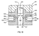
In Fig. 10 besteht der Mischkopf 141 aus einem Gehäuse 142, an welches ein zur Mittelachse spiegelsymmetrisches Einsatzstück 143 angeflanscht ist. Eine Führungsbohrung 144 des Gehäuses 142 für einen Ausstoßkolben 145 setzt sich axial durch das Einsatzstück 143 fort und bildet in diesem eine Mischkammer 146, wenn der Ausstoßkolben 145 die in der Wandung 147 der Mischkammer 146 angeordneten Eintrittsöffnungen 148, 149 freigibt. Das Einsatzstück 143 ist allen Einspritzöffnungen 148, 149 gemeinsam und weist Ausnehmungen 150,151 auf, in welchen Einspritzdüsen 152, 153 austauschbar angeordnet sind. Zu ihnen führen nicht dargestellte Zuführungsleitungen. Die Einspritzdüsen 152, 153 bestehen aus Düsenkörpern 154, 155 mit Düsenöffnungen 156, 157. Zwischen Düsenöffnungen 156, 157 und den Eintrittöffnungen 148, 149 sind im Einsatzstück 143 Kanäle 158, 159 angeordnet, deren Böden als Ablenkflächen 160, 161 ausgebildet sind.In FIG. 10, the mixing
Claims (13)
Applications Claiming Priority (4)
| Application Number | Priority Date | Filing Date | Title |
|---|---|---|---|
| DE3631898 | 1986-09-10 | ||
| DE3631898 | 1986-09-19 | ||
| DE3633343 | 1986-10-01 | ||
| DE19863633343 DE3633343A1 (en) | 1986-09-10 | 1986-10-01 | METHOD AND DEVICE FOR PRODUCING A PLASTIC, IN PARTICULAR FOAM-MAKING, FLOWABLE REACTION MIXTURE FROM AT LEAST TWO FLOWABLE REACTION COMPONENTS IN A CONTINUOUS PROCESS |
Publications (3)
| Publication Number | Publication Date |
|---|---|
| EP0260564A2 EP0260564A2 (en) | 1988-03-23 |
| EP0260564A3 EP0260564A3 (en) | 1988-11-30 |
| EP0260564B1 true EP0260564B1 (en) | 1990-10-17 |
Family
ID=25847641
Family Applications (1)
| Application Number | Title | Priority Date | Filing Date |
|---|---|---|---|
| EP87113036A Expired - Lifetime EP0260564B1 (en) | 1986-09-10 | 1987-09-07 | Method and device for continuously making a plastic material, essentially a liquid reactive mixture for making foam, from at least two liquid components |
Country Status (3)
| Country | Link |
|---|---|
| US (1) | US5093084A (en) |
| EP (1) | EP0260564B1 (en) |
| DE (2) | DE3633343A1 (en) |
Families Citing this family (20)
| Publication number | Priority date | Publication date | Assignee | Title |
|---|---|---|---|---|
| US5445781A (en) * | 1991-08-28 | 1995-08-29 | Centro Sviluppo Settori Impiego S.R.L. | Process for the injection molding of non-precatalyzed polymerizable resins at high-pressure and flow |
| US5279807A (en) * | 1992-05-26 | 1994-01-18 | E. I. Du Pont De Nemours And Company | Method for preparing low-concentration polysilicate microgels |
| US5523063A (en) * | 1992-12-02 | 1996-06-04 | Applied Materials, Inc. | Apparatus for the turbulent mixing of gases |
| DE4316190C1 (en) * | 1993-05-14 | 1994-12-08 | Hennecke Gmbh Maschf | Method and device for processing polyurethane foam waste, in particular flexible foam waste, for recycling as additives in the manufacture of polyurethane |
| DE9402237U1 (en) * | 1994-02-10 | 1995-06-14 | Lutzke Werner | Mixing device for bringing together adhesive components |
| US5562883A (en) * | 1995-05-05 | 1996-10-08 | Davidson Textron Inc. | Solvent flush reaction injection molding mixhead |
| DE29512078U1 (en) * | 1995-07-26 | 1996-03-07 | Macan Zlatko | Mixing and dosing device for silicone |
| DE19644653A1 (en) * | 1996-10-26 | 1998-04-30 | Diversey Gmbh | Method and device for cleaning surfaces heavily contaminated with grease, starch and / or protein dirt, especially in the food industry |
| US6227694B1 (en) | 1996-12-27 | 2001-05-08 | Genus Corporation | High speed collision reaction method |
| DE19960202C2 (en) * | 1999-12-14 | 2003-03-20 | Zsolt Herbak | Device for mixing viscous liquids |
| US20030199595A1 (en) * | 2002-04-22 | 2003-10-23 | Kozyuk Oleg V. | Device and method of creating hydrodynamic cavitation in fluids |
| PT103101B (en) | 2004-04-05 | 2012-07-30 | Faculdade De Engenharia Da Universidade Do Porto | PROCESS OF PRODUCTION OF PLASTIC PARTS BY REACTION, INJECTION AND MOLDING, AND THEIR MACHINE |
| ITMI20061195A1 (en) * | 2006-06-21 | 2007-12-22 | Siviero Enrico | METHOD AND EQUIPMENT WITH LOBATE NOZZLES FOR THE MIXING OF REACTIVE CHEMICAL COMPONENTS |
| WO2009147512A2 (en) * | 2008-06-04 | 2009-12-10 | Inbicon A/S | Devices and methods for discharging pretreated biomass from higher to lower pressure regions |
| US8777478B2 (en) * | 2008-11-27 | 2014-07-15 | Inoac Corporation | Mixing head apparatus for high agitation and smooth flow of liquid blend and molding method using the same |
| PL2593943T3 (en) | 2010-07-15 | 2015-03-31 | Mallinckrodt Nuclear Medicine Llc | Slurry dispenser for radioisotope production |
| US9073017B2 (en) | 2011-06-09 | 2015-07-07 | Meissner Filtration Products, Inc. | Rehydration capsule and method of using the same |
| EP2814773B1 (en) | 2012-02-16 | 2017-05-31 | National Research Council of Canada | Centrifugal microfluidic mixing apparatus and method |
| CN104476713B (en) * | 2014-12-09 | 2017-06-06 | 广西吉顺能源科技有限公司 | A kind of polyurethane foaming machine |
| KR20200039668A (en) * | 2017-08-09 | 2020-04-16 | 가부시키가이샤 시세이도 | Discharge container, customized discharge system having discharge container, and discharge control method in discharge container |
Family Cites Families (8)
| Publication number | Priority date | Publication date | Assignee | Title |
|---|---|---|---|---|
| DE2145547C3 (en) * | 1971-09-11 | 1974-07-11 | Heinrich 3111 Gross Liedern Clasen | Countercurrent injection mixhead |
| FR2211342A1 (en) * | 1972-12-22 | 1974-07-19 | Krauss Maffei Ag | Mixer for liquid plastics giving reduced turbulence - has divergent outlet from mixing chamber leading to mould |
| FR2299578A1 (en) * | 1975-01-28 | 1976-08-27 | Secmer Sa | HEAD FOR MIXING AND SPILLING UNDER PRESSURE OF AT LEAST TWO PRODUCTS |
| US4239732A (en) * | 1979-04-13 | 1980-12-16 | The Martin Sweets Company, Inc. | High velocity mixing system |
| DE3203906A1 (en) * | 1982-02-05 | 1983-08-11 | Elastogran Maschinenbau GmbH, 2844 Lemförde | DEVICE FOR PRODUCING A CHEMICALLY REACTIVE MIXTURE |
| DE3242278A1 (en) * | 1982-11-16 | 1984-05-17 | Basf Ag, 6700 Ludwigshafen | DEVICE FOR PRODUCING A MIXTURE FROM AT LEAST TWO PLASTIC COMPONENTS |
| DE3431112A1 (en) * | 1984-08-24 | 1986-03-06 | Spühl AG, St. Gallen | MIXING HEAD FOR REACTIVE MIXING OF PLASTIC COMPONENTS |
| DE3603430A1 (en) * | 1985-02-08 | 1986-08-14 | Elastogran Maschinenbau GmbH, 2844 Lemförde | Apparatus for mixing multi-component plastics, in particular polyurethane |
-
1986
- 1986-10-01 DE DE19863633343 patent/DE3633343A1/en not_active Withdrawn
-
1987
- 1987-09-07 DE DE8787113036T patent/DE3765610D1/en not_active Expired - Lifetime
- 1987-09-07 EP EP87113036A patent/EP0260564B1/en not_active Expired - Lifetime
-
1990
- 1990-04-09 US US07/506,728 patent/US5093084A/en not_active Expired - Fee Related
Also Published As
| Publication number | Publication date |
|---|---|
| EP0260564A3 (en) | 1988-11-30 |
| DE3633343A1 (en) | 1988-03-17 |
| US5093084A (en) | 1992-03-03 |
| EP0260564A2 (en) | 1988-03-23 |
| DE3765610D1 (en) | 1990-11-22 |
Similar Documents
| Publication | Publication Date | Title |
|---|---|---|
| EP0260564B1 (en) | Method and device for continuously making a plastic material, essentially a liquid reactive mixture for making foam, from at least two liquid components | |
| EP0024608B1 (en) | Method and device for produding mouldings using a free-flowing reaction mixture forming a solid or foamed material | |
| EP0137250B1 (en) | Multiple nozzle for bringing together at least two free-flowing reactants forming plastic, in particular foamed plastic, in order to start the reaction by mixing, and method of operating said multiple nozzle | |
| EP0099045B1 (en) | Method and mixer head for the production of a reactable mixture of at least two flowable reactable components for plastics material | |
| DE3014175A1 (en) | METHOD AND DEVICE FOR INJECTION MIXING AND DISPENSING FOR HIGH-SPEED REACTIONS | |
| EP2403698B1 (en) | Apparatus for producing plastic parts interspersed with reinforcing fibres | |
| EP0064209B1 (en) | Apparatus for the manufacture of a homogeneous or cellular plastics material that forms a reaction mixture from two liquid reactive components | |
| EP0084672B1 (en) | Apparatus for producing a chemically reactive mixture of at least two plastics material components | |
| EP0070486B1 (en) | Method and apparatus for the production of a reaction mixture capable to flow of at least two reaction components reacting together for making homogeneous or foamed material | |
| EP1855858B1 (en) | Mixing head for highly viscous starting material | |
| EP0187360A2 (en) | Mixer mould combination for producing articles from a fluidic reactive mixture of at least two fluidic reactive components | |
| EP0212110B1 (en) | Mixing head for mixing at least two components which form a plastic | |
| DE2346347A1 (en) | MIXING DEVICE FOR THE SHAPING PROCESSING OF PLASTICS, PREFERABLY MULTIPLE LIQUID COMPONENTS | |
| EP0347712A1 (en) | Device for mixing at least two reactive plastic components | |
| DE4103532C1 (en) | ||
| DE60310445T2 (en) | PROCESS AND DEVICE FOR COINJECTION MIXING | |
| DE3200503A1 (en) | "DEVICE FOR MIXING REACTIVE CHEMICAL COMPONENTS" | |
| EP0256157B1 (en) | Mixing head for mixing at least two components which form a plastic | |
| DE4009465C2 (en) | DEVICE FOR MIXING AT LEAST TWO REACTIVE PLASTIC COMPONENTS | |
| DE102004021563A1 (en) | Multi-component mixing head | |
| DE3744434A1 (en) | MIXING DEVICE FOR SYNTHETIC RESINS WITH SEVERAL RESIN COMPONENTS | |
| EP0085876B1 (en) | Apparatus for the production of a reactable mixture | |
| DE3331840A1 (en) | Multi-component nozzle for merging at least two flowable, plastics-forming, especially foam-forming, reactive components in order to initiate the reaction by mixing and process for operating this multi-component nozzle | |
| EP0070487B1 (en) | Apparatus for the production of a reaction mixture capable to flow of at least two reaction components reacting together for making homogeneous or foamed material | |
| DE3603430C2 (en) |
Legal Events
| Date | Code | Title | Description |
|---|---|---|---|
| PUAI | Public reference made under article 153(3) epc to a published international application that has entered the european phase |
Free format text: ORIGINAL CODE: 0009012 |
|
| 17P | Request for examination filed |
Effective date: 19870907 |
|
| AK | Designated contracting states |
Kind code of ref document: A2 Designated state(s): DE FR GB IT |
|
| PUAL | Search report despatched |
Free format text: ORIGINAL CODE: 0009013 |
|
| AK | Designated contracting states |
Kind code of ref document: A3 Designated state(s): DE FR GB IT |
|
| 17Q | First examination report despatched |
Effective date: 19890823 |
|
| GRAA | (expected) grant |
Free format text: ORIGINAL CODE: 0009210 |
|
| AK | Designated contracting states |
Kind code of ref document: B1 Designated state(s): DE FR GB IT |
|
| REF | Corresponds to: |
Ref document number: 3765610 Country of ref document: DE Date of ref document: 19901122 |
|
| GBT | Gb: translation of ep patent filed (gb section 77(6)(a)/1977) | ||
| ET | Fr: translation filed | ||
| ITF | It: translation for a ep patent filed |
Owner name: SOCIETA' ITALIANA BREVETTI S.P.A. |
|
| PLBE | No opposition filed within time limit |
Free format text: ORIGINAL CODE: 0009261 |
|
| STAA | Information on the status of an ep patent application or granted ep patent |
Free format text: STATUS: NO OPPOSITION FILED WITHIN TIME LIMIT |
|
| PGFP | Annual fee paid to national office [announced via postgrant information from national office to epo] |
Ref country code: DE Payment date: 19910820 Year of fee payment: 5 |
|
| PGFP | Annual fee paid to national office [announced via postgrant information from national office to epo] |
Ref country code: GB Payment date: 19910828 Year of fee payment: 5 |
|
| PGFP | Annual fee paid to national office [announced via postgrant information from national office to epo] |
Ref country code: FR Payment date: 19910910 Year of fee payment: 5 |
|
| ITTA | It: last paid annual fee | ||
| 26N | No opposition filed | ||
| PG25 | Lapsed in a contracting state [announced via postgrant information from national office to epo] |
Ref country code: GB Effective date: 19920907 |
|
| GBPC | Gb: european patent ceased through non-payment of renewal fee |
Effective date: 19920907 |
|
| PG25 | Lapsed in a contracting state [announced via postgrant information from national office to epo] |
Ref country code: FR Effective date: 19930528 |
|
| PG25 | Lapsed in a contracting state [announced via postgrant information from national office to epo] |
Ref country code: DE Effective date: 19930602 |
|
| REG | Reference to a national code |
Ref country code: FR Ref legal event code: ST |
|
| PG25 | Lapsed in a contracting state [announced via postgrant information from national office to epo] |
Ref country code: IT Free format text: LAPSE BECAUSE OF NON-PAYMENT OF DUE FEES;WARNING: LAPSES OF ITALIAN PATENTS WITH EFFECTIVE DATE BEFORE 2007 MAY HAVE OCCURRED AT ANY TIME BEFORE 2007. THE CORRECT EFFECTIVE DATE MAY BE DIFFERENT FROM THE ONE RECORDED. Effective date: 20050907 |