EP0187104B1 - Lock with latch and auxiliary bolt - Google Patents
Lock with latch and auxiliary bolt Download PDFInfo
- Publication number
- EP0187104B1 EP0187104B1 EP19850402650 EP85402650A EP0187104B1 EP 0187104 B1 EP0187104 B1 EP 0187104B1 EP 19850402650 EP19850402650 EP 19850402650 EP 85402650 A EP85402650 A EP 85402650A EP 0187104 B1 EP0187104 B1 EP 0187104B1
- Authority
- EP
- European Patent Office
- Prior art keywords
- bolt
- lock
- auxiliary
- principal
- auxiliary bolt
- Prior art date
- Legal status (The legal status is an assumption and is not a legal conclusion. Google has not performed a legal analysis and makes no representation as to the accuracy of the status listed.)
- Expired - Lifetime
Links
Images


Classifications
-
- E—FIXED CONSTRUCTIONS
- E05—LOCKS; KEYS; WINDOW OR DOOR FITTINGS; SAFES
- E05B—LOCKS; ACCESSORIES THEREFOR; HANDCUFFS
- E05B55/00—Locks in which a sliding latch is used also as a locking bolt
- E05B55/12—Locks in which a sliding latch is used also as a locking bolt the bolt being secured by the operation of a hidden parallel member ; Automatic latch bolt deadlocking mechanisms, e.g. using a trigger or a feeler
Definitions
- the invention relates to locks comprising a main bolt of the half-turn type, that is to say beveled and resiliently biased at the exit from the locker, for the purpose of introduction into a keeper (closed position of the lock), an auxiliary bolt also resiliently biased at the exit from the trunk, a range linked to the strike, suitable for opposing the exit of the auxiliary bolt, means for exploiting the re-entry of the auxiliary bolt for blocking purposes of the main bolt in its extended position, and controlled means operable from one of the two sides of the lock, called the "outside" side below, suitable for returning the main bolt to the boot even when the auxiliary bolt is retracted.
- opening the lock from the outside constantly requires the use of a key or other device under control such as a coding keyboard or a magnetic card.
- each of the authorization periods in question can for example be initiated by pressing a simple electric push button by an authorized person located in a room inaccessible to the users concerned, but in a place from this room from where she can see and identify these users, or by the introduction, by such a user, of a magnetic card coded in an appropriate reader connected to the lock, and the end of such a period authorization can then be determined by simply closing the lock following its opening.
- the locks of the type in question are essentially characterized according to the invention in that they also comprise an auxiliary strike secured to the main strike and suitable for receiving the auxiliary bolt when the door is closed, a constituent plug.
- plug suitable for moving in the auxiliary strike between two stable positions corresponding respectively to the release and the plugging of this strike means, preferably electric, to move this plug from one to the other from its two stable positions and vice versa, an external control handle and a connecting mechanism capable of kinematically linking this handle to the main bolt so that an actuation of the handle results in a retraction of the two bolts if they have come out both and on the contrary is inoperative vis-à-vis the main bolt as long as the auxiliary bolt is in its retracted position or s only partially out.
- the holding mechanism comprises a blocking stop carried by a link which is permanently elastically urged towards an angular position for which this stop is on the re-entry path of the main bolt, this rod being mounted so as to be constantly urged in the opposite direction from the previous, towards a position authorizing the re-entry of the main bolt, by the spring which biases the auxiliary bolt at the outlet, and the connection mechanism interposed between the outer handle and the bolts comprises an arm angularly integral with the handle and a slide actuable by this arm and linked to the main bolt,
- the rod carrying the blocking stop is actuated by the spring which biases the auxiliary bolt at the outlet by means of a lug secured to this auxiliary bolt and of a lever bearing on the one hand against this rod constantly and on the other hand against this tab only when the auxiliary bolt is completely extended or almost completely removed from the trunk,
- the holding mechanism is arranged so as to break the continuity of the connecting mechanism when the auxiliary bolt is retracted
- the lock comprises, in addition to the above external control handle, an internal control handle and these two control handles are coaxial and separated axially from each other by an intermediate pad mounted crazy on a support secured to the lock safe, tablet preferably constituting the common bottom of two buckets open to the two sides of the lock,
- a lock with two handles comprising, in the manner defined above, a connecting rod carrying a locking stop and a slide, further comprises an arm angularly integral with the interior handle and a crew actuable by this arm , a crew comprising on the one hand a heel capable of interacting with the link so as to push the stopper back into its unlocked position, that is to say outside the path of re-entry of the main bolt and on the other hand a range suitable for interacting with a range of the slider for the purpose of hooking said crew on this slider at least as soon as the heel has reached its position corresponding to the release of the main bolt,
- a lock comprising, as defined above, a connecting rod carrying a blocking stop and a slide, further comprises a rotary bit mechanism controlled by a key and an intermediate mechanism itself comprising a tab suitable for being driven by the bit , first means linked to this tab and suitable for pushing the locking stop in its unlocking position and second means for connecting said tab to the slide at least as soon as the first means have released the main bolt.
- the invention includes, apart from these main provisions, certain other provisions which are preferably used at the same time and which will be more explicitly discussed below.
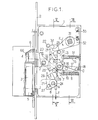
- FIGS. 1 to 3, of these drawings show a portion of a lock established according to the invention, cover removed, in three distinct situations corresponding respectively: the first, in the closed state of the lock with its two bolts extended, situation which allows opening by simple actuation of the external handle; the second, in the open state of said lock; and the third, in its closed state with blocking of the external handle due to the retraction of the auxiliary bolt.
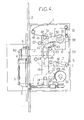
- FIG. 4 shows other portions of the same lock.
- Figures 5 and 6 are sections of said lock respectively according to V-V and VI-VI, Figure 1.
- Figures 7 and 8 show respectively in side view and in perspective view two variants of locks also established according to the invention.
- the lock comprises, on the one hand, a trunk 1 secured to a headrest 2 crossed by a main bolt 3 and by an auxiliary bolt 4 and, on the other hand, a housing comprising a main keeper 5 suitable for receiving contiguously the main bolt 3 for the purpose of "closing" the lock and an auxiliary strike 6 suitable for receiving the auxiliary bolt 4.
- the main bolt 3 is of the half-turn type, that is to say beveled with a flat or curved ramp and it can be the same for the auxiliary bolt 4 although this is not essential, as specified below.
- the main bolt 3 comprises a tail 7 guided horizontally between two idle rollers 8 and 9, the axes A and B of which are linked to the boot and it is constantly stressed at the outlet from the boot 1 by a helical compression spring 10 surrounding a horizontal baluster 11 secured to the trunk.
- the auxiliary bolt 4 comprises a tail 12 terminated by a folded fork 13 and it is guided horizontally by overlapping, by this fork, of a horizontal column 14 secured to the trunk.
- This auxiliary bolt 4 is constantly stressed at the outlet from the trunk 1 by a helical compression spring 15 surrounding the baluster 14.
- auxiliary bolt its position retracted into the boot automatically ensures the locking of the main bolt in its extended position, whether the output of the latter has occurred before or after the retraction of the auxiliary bolt.
- the locking finger 7 crosses vertically downwards the level of the axis C of this link, which allows it to effectively play its role of horizontal blocking: in fact, when finger 16 is below this level, the horizontal thrust exerted to the right on this finger 16 tends to apply the rod 17 against its end-of-travel stop whereas, when finger 16 is above said level, the same thrust tends to return it to its release positions by angular displacement upwards around the C axis.
- Means are provided so that the re-entry of the main bolt 3 into the boot 1 automatically results in that of the auxiliary bolt 4, the beginnings of these two re-entries preferably being offset by a slight delay.
- These means include a slide 21 guided vertically between fixed studs 22, 23 and 24 secured to the trunk, this derneir stud 24 serving as a journal for the roller 8 above.
- the slider 21 is kinematically linked to the tail 7 by an angle return bend 25 mounted pivoting about the axis A and having two forks perpendicular to each other which overlap jointly, the first, a pin 26 secured to the tail 7 and the second, a pin 27 secured to the slide 21.
- This slide further comprises a pin 28 suitable for coagulating with a quarter-circle sector 29 mounted idly around the axis B and suitable for coagulating itself with a clearance j with a pin 30 secured to the tail 12.
- the game j in question makes it possible to start the reentry of the auxiliary bolt 4 only after the main bolt 3 has traveled a sufficient reentry stroke so that the end of its tail 7 has exceeded the level of the locking finger 16: this delay prevents the re-entry of the bolt 3 from being blocked by the stop of its tail against this finger.
- FIGS 1 to 3 show at 31 an external control handle cut along its square operating rod.
- this handle is connected to the two bolts in such a way that its simple rotation allows the main bolt 3 to be returned to the boot when the auxiliary bolt 4 is released at the same time as this main bolt and, on the contrary such a command is prevented when the main bolt is extended and the auxiliary bolt is retracted.
- the main bolt is controlled from this handle 31 by means of the slide 21.
- the handle 31 is angularly integral with an arm 32 angularly biased in the direction of the arrow F, by a helical tension spring 33, towards a rest position for which this arm abuts against the stud 23.
- the re-entry of the auxiliary bolt 4 in the trunk of the lock has the effect of putting the finger 16 in its locking position and the locking of the handle 31 is ultimately ensured by the stop of the tail 7 of the main bolt against this finger 16.
- this stop is very solid and withstands the forcing attempts which may be exerted on it by subjecting the handle 31 to intense angular forces.
- the slide 21 above is split into two slides placed one against the other. These two slides can be joined together by a mobile pin which is guided, parallel to the axes A, B, C and D, in appropriate holes in the slides and which is resiliently biased against a ramp secured to the lever 19. This ramp is drawn of so that the mutual solidarity of the two slides is deleted when the auxiliary bolt 4 enters the boot and vice versa.
- a rack on the bolt tail 7 or on the slide 21 there is provided on the one hand a rack on the bolt tail 7 or on the slide 21 and on the other hand a gear train in mutual engagement between the handle 31 and this rack.
- the pinion, of this train, furthest from the handle is mounted on a second link similar to the link 17 above, and this second link is resiliently biased towards an angular position for which the pinion considered engages with the rack.
- the tilting of the lever 19 above, due to the return of the auxiliary bolt 4 are then used to move the second link in the direction of disengagement and vice versa.
- the lock illustrated in Figures 1 to 6 can also be opened, regardless of the position initially retracted or extended from the auxiliary bolt 4, from the simple rotation of an interior handle 35 (fig. 4) or a key outer 36 suitable for driving a bit 37, for example by means of a locking assembly of the rotating barrel type.
- the handle 35 is angularly secured to an arm 38 angularly biased in the direction of the arrow G towards a rest position for which it abuts against the stud 23.
- a torsion spring 45 bears against the slide 41 so as to constantly urge it in the direction which separates the heel 42 from the link 17, which puts this slide 41 into abutment against the stud 24.
- a third slide 46 is provided parallel to the previous two and guided vertically by the same studs as the latter.
- These means consist of two pins 48 and 49 secured respectively to the second slide 41 and the third slide 46 and by an arm 50 mounted idly around the axis of the handle 35 and extending contiguously between the two pins 48 and 49.
- the two outer 31 and inner 35 handles are coaxial, but they are separated axially from each other by a pad 55 (FIG. 6) mounted loosely on a support linked to the trunk 1.
- This pellet 55 advantageously constitutes the common bottom of two cylindrical cups 56 and 57 open respectively towards the two sides of the lock and suitable for receiving respectively thickened portions, with cylindrical outline of revolution, of the two arms 32 and 38, portions themselves hollowed out by square holes 58.59 suitable for receiving the rods of the two handles concerned in a joint manner.
- the support of the assembly formed by the pellet 55 and by the two cylindrical cups 56 and 57 which extend it comprises, in the embodiment illustrated in Figure 6, two hollow pillars 60 integral with the trunk 1 and each successively having one end set in the bottom of this box, which it crosses, a cylindrical shoulder forming a spacer and a tubular barrel.
- This barrel itself contiguously crosses a first plate 61 crossed by one of the buckets 57, then a washer 62 of the same thickness as the annular portion of the arm 50, which portion encircles the pellet 55, then a second plate 63 traversed by the another cup 56, then a spacer ring 64 and finally the lid 65 of the trunk.
- the axes A, B, C, D and the axes of the studs 22 and 23 and the pillars 60 are all hodzontal and parallel to the common axis of the handles 31 and 35 as well as to the axis of the key 36, that is ie perpendicular to the direction of horizontal sliding of the bolts.
- the inputs of the auxiliary bolt 4 into the trunk 1 and its outputs out of this trunk can be controlled in any desirable manner.
- the movement of the plug 66 is itself controlled electrically from a distance, but it could also be mechanical.
Landscapes
- Lock And Its Accessories (AREA)
- Details Of Connecting Devices For Male And Female Coupling (AREA)
Description
L'invention est relative aux serrures comportant un pêne principal de type demi-tour, c'est-à-dire biseauté et sollicité élastiquement à la sortie hors du coffre de la serrure, aux fins d'introduction dans une gâche (position de fermeture de la serrure), un pêne auxiliaire également sollicité élastiquement à la sortie hors du coffre, une portée liée à la gâche, propre à s'opposer à la sortie du pêne auxiliaire, des moyens pour exploiter la rentrée du pêne auxiliaire aux fins de blocage du pêne principal en sa position sortie, et des moyens contrôlés actionnables depuis l'un des deux côtés de la serrure, dit côté "extérieur" ci-après, propres à rentrer le pêne principal dans le coffre même lorsque le pêne auxiliaire est rentré.The invention relates to locks comprising a main bolt of the half-turn type, that is to say beveled and resiliently biased at the exit from the locker, for the purpose of introduction into a keeper (closed position of the lock), an auxiliary bolt also resiliently biased at the exit from the trunk, a range linked to the strike, suitable for opposing the exit of the auxiliary bolt, means for exploiting the re-entry of the auxiliary bolt for blocking purposes of the main bolt in its extended position, and controlled means operable from one of the two sides of the lock, called the "outside" side below, suitable for returning the main bolt to the boot even when the auxiliary bolt is retracted.
Une telle serrure a par exemple été décrite dans le brevet US 1 508 668.Such a lock has for example been described in US Pat. No. 1,508,668.
L'avantage présenté par de telles serrures réside en ce qu'il n'est pas possible de faire rentrer le pêne principal dans le coffre, à partir de l'extérieur de la serrure, à l'aide simplement d'un instrument mince glissé entre ce coffre et la gâche, tant que le pêne auxiliaire se trouve en sa position rentrée.The advantage of such locks is that it is not possible to fit the main bolt into the trunk, from the outside of the lock, simply using a thin slipped instrument between this box and the strike, as long as the auxiliary bolt is in its retracted position.
Il est à noter qu'un tel avantage ne pourrait être obtenu avec une serrure dans laquelle ce serait la sortie du pêne auxiliaire, et non sa rentrée, qui serait exploitée pour bloquer le pêne principal en sa position sortie.It should be noted that such an advantage could not be obtained with a lock in which it would be the exit of the auxiliary bolt, and not its reentry, which would be used to block the main bolt in its extended position.
Avec les modes de réalisation connus des serrures du genre considéré, l'ouverture de la serrure depuis l'extérieur nécessite constamment l'usage d'une clé ou autre dispositif sous contrôle tel qu'un clavier de codage ou qu'une carte magnétique.With the known embodiments of locks of the type considered, opening the lock from the outside constantly requires the use of a key or other device under control such as a coding keyboard or a magnetic card.
Or il existe de nombreuses applications pour lesquelles il est intéressant de pouvoir autoriser certains usagers à commander l'ouverture de la serrure, au cours de certaines périodes, par simple actionnement d'une poignée de commande extérieure, un tel actionnement étant au contraire rendu inopérant en dehors desdites périodes d'autorisation: chacune des périodes d'autorisation en question peut être par exemple initiée par l'appui d'un simple bouton-poussoir électrique par une personne habilitée située dans un local inaccessible des usagers considérés, mais en un endroit de ce local d'où elle peut voir-et identifier ces usagers, ou encore par l'introduction, par un tel usager, d'une carte magnétique codée dans un lecteur approprié relié à la serrure, et la fin d'une telle période d'autorisation peut être ensuite déterminée par la simple fermeture de la serrure consécutive àson ouverture.However, there are numerous applications for which it is advantageous to be able to authorize certain users to control the opening of the lock, during certain periods, by simple actuation of an external control handle, such actuation being on the contrary rendered inoperative. outside of said authorization periods: each of the authorization periods in question can for example be initiated by pressing a simple electric push button by an authorized person located in a room inaccessible to the users concerned, but in a place from this room from where she can see and identify these users, or by the introduction, by such a user, of a magnetic card coded in an appropriate reader connected to the lock, and the end of such a period authorization can then be determined by simply closing the lock following its opening.
C'est précisément le but essentiel de l'invention de permettre de telles commandes.It is precisely the essential aim of the invention to allow such commands.
A cet effet les serrures du genre en question sont essentiellement caractérisées selon l'invention en ce qu'elles comportent en outre une gâche auxiliaire solidaire de la gâche principale et propre à recevoir le pêne auxiliaire lors de la fermeture de la porte, un bouchon constitutif de la portée ci-dessus, bouchon propre à se déplacer dans la gâche auxiliaire entre deux positions stables correspondant respectivement au dégagement et au bouchage de cette gâche, des moyens, de préférence électriques, pour déplacer ce bouchon de l'une à l'autre de ses deux positions stables et inversement, une poignée de commande extérieure et un mécanisme de liaison propre à lier cinématiquement cette poignée au pêne principal de façon telle qu'un actionnement de la poignée se traduise par une rentrée des deux pênes s'ils sont sortis tous les deux et au contraire soit inopérante vis-à-vis du pêne principal tant que le pêne auxiliaire se trouve en sa position rentrée ou seulement partiellement sortie.To this end, the locks of the type in question are essentially characterized according to the invention in that they also comprise an auxiliary strike secured to the main strike and suitable for receiving the auxiliary bolt when the door is closed, a constituent plug. of the above range, plug suitable for moving in the auxiliary strike between two stable positions corresponding respectively to the release and the plugging of this strike, means, preferably electric, to move this plug from one to the other from its two stable positions and vice versa, an external control handle and a connecting mechanism capable of kinematically linking this handle to the main bolt so that an actuation of the handle results in a retraction of the two bolts if they have come out both and on the contrary is inoperative vis-à-vis the main bolt as long as the auxiliary bolt is in its retracted position or s only partially out.
Dans des modes de réalisation préférés, on a recours en outre à l'une et/ou à l'autre des dispositions suivantes:
- les deux pênes sont reliés entre eux par un mécanisme d'entraînement agencé de façon telle que, lorsque ces deux pênes sont sortis, la rentrée du pêne principal dans le coffre entraîne celle du pêne auxiliaire, mais avec un retard suffisant pour que cette dernière rentrée n'entrave pas celle du pêne principal,
- dans une serrure selon l'alinéa précédent, le pêne auxiliaire est plus court que le pêne principal,
- dans une serrure selon au moins l'alinéa qui précède le précédent, le mécanisme d'entraînement du pêne auxiliaire par le pêne principal est tel que le déplacement du second soit plus rapide que celui du premier et que les fins des rentrées des deux pênes soient simultanées,
- the two bolts are connected together by a drive mechanism arranged in such a way that, when these two bolts are out, the re-entry of the main bolt into the boot causes that of the auxiliary bolt, but with a delay sufficient for this latter re-entry does not hinder that of the main bolt,
- in a lock according to the preceding paragraph, the auxiliary bolt is shorter than the main bolt,
- in a lock according to at least the paragraph preceding the previous one, the mechanism for driving the auxiliary bolt by the main bolt is such that the displacement of the second is faster than that of the first and that the ends of the returns of the two bolts are simultaneous,
le mécanisme de maintien comprend une butée de blocage portée par une biellette sollicitée élastiquement en permanence vers une position angulaire pour laquelle cette butée se trouve sur la trajectoire de rentrée du pêne principal, cette biellette étant montée de façon à être constamment sollicitée en sens inverse du précédent, vers une position autorisant la rentrée du pêne principal, par le ressort qui sollicite le pêne auxiliaire à la sortie, et le mécanisme de liaison interposé entre la poignée extérieure et les pênes comporte un bras angulairement solidaire de la poignée et un coulisseau actionnable par ce bras et lié au pêne principal,the holding mechanism comprises a blocking stop carried by a link which is permanently elastically urged towards an angular position for which this stop is on the re-entry path of the main bolt, this rod being mounted so as to be constantly urged in the opposite direction from the previous, towards a position authorizing the re-entry of the main bolt, by the spring which biases the auxiliary bolt at the outlet, and the connection mechanism interposed between the outer handle and the bolts comprises an arm angularly integral with the handle and a slide actuable by this arm and linked to the main bolt,
la biellette porteuse de la butée de blocage est actionnée par le ressort qui sollicite le pêne auxiliaire à la sortie par l'intermédiaire d'une patte solidaire de ce pêne auxiliaire et d'un levier prenant appui d'une part contre cette biellette constamment et d'autre part contre cette patte uniquement lorsque le pêne auxiliaire est totalement sorti ou presque totalement sorti du coffre,the rod carrying the blocking stop is actuated by the spring which biases the auxiliary bolt at the outlet by means of a lug secured to this auxiliary bolt and of a lever bearing on the one hand against this rod constantly and on the other hand against this tab only when the auxiliary bolt is completely extended or almost completely removed from the trunk,
le mécanisme de maintien est agencé de façon à rompre la continuité du mécanisme de liaison lorsque le pêne auxiliaire est rentré,the holding mechanism is arranged so as to break the continuity of the connecting mechanism when the auxiliary bolt is retracted,
la serrure comprend, en plus de la poignée de commande extérieure ci-dessus, une poignée de commande intérieure et ces deux poignées de commande sont coaxiales et séparées axialement l'une de l'autre par une pastille intermédiaire montée folle sur un support solidaire du coffre de la serrure, pastille constituant de préférence le fond commun de deux godets ouverts vers les deux côtés de la serrure,the lock comprises, in addition to the above external control handle, an internal control handle and these two control handles are coaxial and separated axially from each other by an intermediate pad mounted crazy on a support secured to the lock safe, tablet preferably constituting the common bottom of two buckets open to the two sides of the lock,
une serrure à deux poignées selon l'alinéa précédent, comportant de la manière définie ci- dessus une biellette porteuse d'une butée de blocage et un coulisseau, comporte en outre un bras angulairement solidaire de la poignée intérieure et un équipage actionnable par ce bras, équipage comportant d'une part un talon propre à coagir avec la biellette de façon à repousser la butée en sa position de déblocage, c'est-à-dire hors de la trajectoire de rentrée du pêne principal et d'autre part une portée propre à coagir avec une portée du coulisseau aux fins d'accrochage dudit équipage sur ce coulisseau au moins dès que le talon est parvenu en sa position correspondant au déblocage du pêne principal,a lock with two handles according to the preceding paragraph, comprising, in the manner defined above, a connecting rod carrying a locking stop and a slide, further comprises an arm angularly integral with the interior handle and a crew actuable by this arm , a crew comprising on the one hand a heel capable of interacting with the link so as to push the stopper back into its unlocked position, that is to say outside the path of re-entry of the main bolt and on the other hand a range suitable for interacting with a range of the slider for the purpose of hooking said crew on this slider at least as soon as the heel has reached its position corresponding to the release of the main bolt,
une serrure comportant de la manière définie cidessus une biellette porteuse d'une butée de blocage et un coulisseau, comporte en outre un mécanisme à panneton tournant commandé par une clé et un mécanisme intercalaire comportant lui-même une patte propre à être entraînée par le panneton, des premiers moyens liés à cette patte et propres à repousser la butée de blocage en sa position de déblocage et des seconds moyens pour relier ladite patte au coulisseau au moins dès que les premiers moyens ont assuré le déblocage du pêne principal.a lock comprising, as defined above, a connecting rod carrying a blocking stop and a slide, further comprises a rotary bit mechanism controlled by a key and an intermediate mechanism itself comprising a tab suitable for being driven by the bit , first means linked to this tab and suitable for pushing the locking stop in its unlocking position and second means for connecting said tab to the slide at least as soon as the first means have released the main bolt.
L'invention comprend, mises à part ces dispositions principales, certaines autres dispositions qui s'utilisent de préférence en même temps et dont il sera plus explicitement question ci-après.The invention includes, apart from these main provisions, certain other provisions which are preferably used at the same time and which will be more explicitly discussed below.
Dans ce qui suit, l'on va décrire des modes de réalisation préférés de l'invention en se référant aux dessins ci-annexés d'une manière bien entendu non limitative.In what follows, we will describe preferred embodiments of the invention with reference to the accompanying drawings in a manner of course not limiting.
Les figures 1 à 3, de ces dessins, montrent une portion d'une serrure établie selon l'invention, couvercle enlevé, en trois situations distinctes correspondant respectivement: la première, à l'état fermé de la serrure avec ses deux pênes sortis, situation qui permet l'ouverture par simple actionnement de la poignée extérieure; la seconde, à l'état ouvert de ladite serrure; et la troisième, à son état fermé avec blocage de la poignée extérieure du fait de la rentrée du pêne auxiliaire.FIGS. 1 to 3, of these drawings, show a portion of a lock established according to the invention, cover removed, in three distinct situations corresponding respectively: the first, in the closed state of the lock with its two bolts extended, situation which allows opening by simple actuation of the external handle; the second, in the open state of said lock; and the third, in its closed state with blocking of the external handle due to the retraction of the auxiliary bolt.
La figure 4 montre d'autres portions de la même serrure.Figure 4 shows other portions of the same lock.
Les figures 5 et 6 sont des coupes de ladite serrure respectivement selon V-V et VI-VI, figure 1.Figures 5 and 6 are sections of said lock respectively according to V-V and VI-VI, Figure 1.
Les figures 7 et 8 représentent respectivement en vue de côté et en vue perspective deux variantes de serrures également établies selon, l'invention.Figures 7 and 8 show respectively in side view and in perspective view two variants of locks also established according to the invention.
Dans chaque cas, la serrure comprend, d'une part, un coffre 1 solidaire d'une têtière 2 traversée par un pêne principal 3 et par un pêne auxiliaire 4 et, d'autre part, unboîtier comportant une gâche principale 5 propre à recevoir jointivement le pêne principal 3 aux fins de "fermeture" de la serrure et une gâche auxiliaire 6 propre à recevoir le pêne auxiliaire 4.In each case, the lock comprises, on the one hand, a
Pour la clarté de l'exposé, on supposera dans ce qui suit, en décrivant la serrure illustrée sur les figures 1 à 6, que les deux pênes sont disposés verticalement l'un au-dessus de l'autre et se déplacent horizontalement, mais il va de soi que la serrure considérée peut être orientée différemment.For the sake of clarity, it will be assumed in the following, when describing the lock illustrated in FIGS. 1 to 6, that the two bolts are arranged vertically one above the other and move horizontally, but it goes without saying that the lock in question can be oriented differently.
Le pêne principal 3 est du type demi-tour, c'est-à-dire biseauté avec une rampe plane ou bombée et il peut en être de même pour le pêne auxiliaire 4 bien que cela ne soit pas indispensable, comme précisé plus loin.The
Le pêne principal 3 comprend une queue 7 guidée horizontalement entre deux galets fous 8 et 9 dont les axes A et B sont liés au coffre et il est constamment sollicité à la sortie hors du coffre 1 par un ressort hélicoïdal de compression 10 entourant une colonnette horizontale 11 solidaire du coffre.The
Le pêne auxiliaire 4 comprend une queue 12 terminée par une fourche rabattue 13 et il est guidé horizontalement par chevauchement, par cette fourche, d'une colonnette horizontale 14 solidaire du coffre.The
Ce pêne auxiliaire 4 est constamment sollicité à la sortie hors du coffre 1 par un ressort hélicoïdal de compression 15 entourant la colonnette 14.This
Le rôle du pêne auxiliaire est le suivant: sa position rentrée dans le coffre assure automatiquement le blocage du pêne principal en sa position sortie, que la sortie de ce dernier soit intervenue avant ou après la rentrée du pêne auxiliaire.The role of the auxiliary bolt is as follows: its position retracted into the boot automatically ensures the locking of the main bolt in its extended position, whether the output of the latter has occurred before or after the retraction of the auxiliary bolt.
Le mécanisme assurant ce blocage comprend:
- un doigt de
blocage 16 porté par unebiellette 17 montée pivotante autour d'un axe fixe C lié au coffre, doigt susceptible de se trouver sur la trajectoire de rentrée de laqueue 7 pour certaines positions angulaires de la biellette dites "de blocage" ou au contraire hors de cette trajectoire pour d'autres positions angulaires de ladite biellette, dites "de déblocage", - un ressort de
torsion 18 sollicitant constamment la biellette vers ses positions angulaires de blocage, - et un levier coudé 19 monté pivotant autour d'un axe fixe D du coffre.
- a locking
finger 16 carried by arod 17 pivotally mounted about a fixed axis C linked to the trunk, finger likely to be on the re-entry path of thetail 7 for certain angular positions of the rod called "blocking" or on the contrary, outside of this trajectory for other angular positions of said rod, called "unlocking", - a
torsion spring 18 constantly urging the link towards its angular locking positions, - and a
bent lever 19 pivotally mounted about a fixed axis D of the trunk.
Pour la position sortie du pêne auxiliaire 4 (fig. 1) une extrémité du levier coudé 19 prend appui contre une patte rabattue 20 de la queue 12 et l'autre extrémité de ce levier coudé 19 prend appui contre la biellette 17 de façon à la maintenir en une position de déblocage: à cet effet, la force du ressort 18 est choisie de façon à être surmontée par celle du ressort 15.For the extended position of the auxiliary bolt 4 (fig. 1) one end of the
Si, à partir de cette situation, on fait rentrer progressivement le pêne auxiliaire 4 en contrariant l'effort antagoniste du ressort 15, on observe d'abord des basculements de la biellette 17 et du levier 19, sous l'effet de la détente du ressort 18, et ce jusqu'à butée angulaire de la biellette contre une pièce de la serrure alors solidaire du coffre.If, starting from this situation, the
A partir de cet instant, qui intervient pour une rentrée relativement peu profonde du pêne auxiliaire, correspondant par exemple au I/5 de sa course de rentrée, la pour-suite de ladite rentrée n'a plus de conséquence sur le mécanisme de blocage 16-19 et la patte 20 s'écarte du levier 19: la plus grande partie de la rentrée du pêne auxiliaire correspond donc à cet égard à une course morte m (fig.3).From this moment, which intervenes for a relatively shallow reentry of the auxiliary bolt, corresponding for example to I / 5 of its reentry stroke, the continuation of said reentry no longer has any effect on the locking mechanism 16-19 and the
Lors du basculement indiqué ci-dessus de la biellette 17, le doigt de blocage 7 franchit verticalement vers le bas le niveau de l'axe C de cette biellette, ce qui lui permet de jouer efficacement son rôle de blocage horizontal: en effet, lorsque le doigt 16 est en dessous de ce niveau, la poussée horizontale exercée vers la droite sur ce doigt 16 tend à appliquer la biellette 17 contre sa butée de fin de course alors que, lorsque le doigt 16 se trouve audessus dudit niveau, la même poussée tend à la renvoyer vers ses positions de déblocage par déplacement angulaire vers le haut autour de l'axe C.During the tilting indicated above of the
Des moyens sont prévus pour que la rentrée du pêne principal 3 dans le coffre 1 se traduise automatiquement par celle du pêne auxiliaire 4, les débuts de ces deux rentrées étant de préférence décalés d'un léger retard.Means are provided so that the re-entry of the
Ces moyens comprennent un coulisseau 21 guidé verticalement entre des plots fixes 22, 23 et 24 solidaires du coffre, ce derneir plot 24 servant de tourillon pour le galet 8 ci-dessus.These means include a
Le coulisseau 21 est lié cinématiquement à la queue 7 par un coude de renvoi d'angle 25 monté pivotant autour de l'axe A et présentant deux fourches perpendiculaires entre elles qui chevauchent jointivement, la première, un pion 26 solidaire de la queue 7 et la seconde, un pion 27 solidaire du coulisseau 21.The
Ce coulisseau comprend en outre un pion 28 propre à coagir avec un secteur en quart de cercle 29 monté fou autour de l'axe B et propre à coagir lui-même avec un jeu j avec un pion 30 solidaire de la queue 12.This slide further comprises a
Le jeu j en question permet de faire débuter la rentrée du pêne auxiliaire 4 seulement après que le pêne principal 3 ait parcouru une course de rentrée suffisante pour que l'extrémité de sa queue 7 ait dépassé le niveau du doigt de blocage 16: ce retard empêche que la rentrée du pêne 3 soit alors bloquée par butée de sa queue contre ce doigt.The game j in question makes it possible to start the reentry of the
Pour permettre toutefois d'achever en même temps les rentrées des deux pênes 3 et 4 dans le coffre, malgré ce retard pris au départ par le pêne auxiliaire 4, on donne à ce dernier des dimensions plus petites qu'au pêne principal 3 et/ou l'on impose un coefficient multiplicateur entre les déplacements des deux pênes, notamment en donnant deux valeurs différentes au rapport de transmission du mouvement entre le coulisseau 21 et le pêne 3 et au rapport de transmission du mouvement entre ledit coulisseau 21 et le pêne 4.To allow however to complete at the same time the returns of the two
L'entraînement du pêne auxiliaire par le pêne principal permet même de donner au premier une forme non biseautée dans la mesure où, bien entendu, cette forme n'entrave pas la commande de la rentrée du pêne principal par simple butée de sa rampe inclinée contre la gâche correspondante.The driving of the auxiliary bolt by the main bolt even makes it possible to give the first a non-bevelled shape insofar as, of course, this shape does not hamper the control of the re-entry of the main bolt by simple stop of its ramp inclined against the corresponding keeper.
Les figures 1 à 3 font apparaître en 31 une poignée de commande extérieure coupée selon sa tige de manoeuvre, carrée.Figures 1 to 3 show at 31 an external control handle cut along its square operating rod.
Comme indiqué ci-dessus, cette poignée est reliée aux deux pênes de façon telle que sa simple rotation permette de faire rentrer le pêne principal 3 dans le coffre lorsque le pêne auxiliaire 4 est sorti en même temps que ce pêne principal et qu'au contraire une telle commande soit empêchée lorsque le pêne principal est sorti et que le pêne auxiliaire est rentré.As indicated above, this handle is connected to the two bolts in such a way that its simple rotation allows the
A cet effet la commande du pêne principal à partir de cette poignée 31 est effectuée par l'intermédiaire du coulisseau 21.To this end, the main bolt is controlled from this
La poignée 31 est solidaire angulairement d'un bras 32 sollicité angulairement dans le sens de la flèche F, par un ressort hélicoïdal de traction 33, vers une position de repos pour laquelle ce bras vient en butée contre le plot 23.The
En faisant tourner la poignée 31 dans le sens inverse de la flèche F, le bras 32 vient buter contre un pion 34 du coulisseau 21.By rotating the
Comme ce coulisseau 21 est lié cinématiquement à la queue du pêne principal 3, la rentrée de ce pêne est possible, en réponse à une simple rotation de la poignée 31, tant que le pion de blocage 16 n'est pas situé sur la trajectoire de rentrée dudit pêne, c'est-à-dire tant que le pêne auxiliaire 4 est totalement sorti ou presque totalement sorti.As this
Si au contraire le doigt 16 se trouve en position de blocage, par suite de la rentrée du pêne auxiliaire 4, le coulisseau 21 est lui-même bloqué, ainsi que la poignée 31.If, on the contrary, the
Dans le mode de réalisation décrit ci-dessus, la rentrée du pêne auxiliaire 4 dans le coffre de la serrure a pour effet de mettre le doigt 16 en sa position de blocage et la condamnation de la poignée 31 est assurée en définitive par la butée de la queue 7 du pêne principal contre ce doigt 16.In the embodiment described above, the re-entry of the
Il faut donc que cette butée soit très solide et résiste aux tentatives de forcement susceptibles d'être exercées sur elle en soumettant la poignée 31 à des efforts angulaires intenses.It is therefore necessary that this stop is very solid and withstands the forcing attempts which may be exerted on it by subjecting the
Selon une variante permettant d'écarter tout risque de forcement de ce type, la rentrée du pêne principal se traduit encore éventuellement par l'effet explicité ci-dessus, mais surtout par une rupture de la liaison cinématique entre la poignée 31 et le pêne principal 3.According to a variant making it possible to eliminate any risk of forcing of this type, the re-entry of the main bolt still possibly results in the effect explained above, but above all by a break in the kinematic connection between the
Une telle rupture peut être réalisée de nombreuses manières, dont deux sont indiquées ci-après.Such a break can be achieved in many ways, two of which are indicated below.
Selon la première réalisation, le coulisseau 21 ci-dessus est dédoublé en deux coulisses placées l'une contre l'autre. Ces deux coulisses sont solidarisables entre elles par un pion mobile qui est guidé, parallèlement aux axes A, B, C et D, dans des trous appropriés des coulisses et qui est sollicité élastiquement contre une rampe solidaire du levier 19. Cette rampe est dessinée de façon telle que la solidarisation mutuelle des deux coulisses soit supprimée quand le pêne auxiliaire4 rentre dans le coffre et inversement.According to the first embodiment, the
Selon la seconde réalisation, on prévoit d'une part une crémaillère sur la queue de pêne 7 ou sur le coulisseau 21 et d'autre part un train de pignons en prise mutuelle entre la poignée 31 et cette crémaillère. Le pignon, de ce train, le plus éloigné de la poignée est monté sur une seconde biellette analogue à la biellette 17 ci-dessus, et cette seconde biellette est sollicitée élastiquement vers une position angulaire pour laquelle le pignon considéré embraye avec la crémaillère. Les basculements, du levier 19 ci-dessus, dus aux rentrées du pêne auxiliaire 4, sont alors exploités pour déplacer la seconde biellette dans le sens du débrayage et inversement.According to the second embodiment, there is provided on the one hand a rack on the
La serrure illustrée sur les figures 1 à 6 peut également être ouverte, quelle que soit la position initialement rentrée ou sortie du pêne auxiliaire 4, à partir de la simple rotation d'une poignée intérieure 35 (fig. 4) ou d'une clé extérieure 36 propre à entraîner un panneton 37, par exemple par l'intermédiaire d'un ensemble de verrouillage du type à canon tournant.The lock illustrated in Figures 1 to 6 can also be opened, regardless of the position initially retracted or extended from the
A cet effet la poignée 35 est angulairement solidaire d'un bras 38 sollicité angulairement dans le sens de la flèche G vers une position de repos pour laquelle il vient en butée contre le plot 23.To this end, the
Si l'on actionne cette poignée 35 en sens inverse de la flèche G. le bras 38 vient en butée contre un pion 40 solidaire d'un second coulisseau 41 (fig. 4 et 5) parallèle au coulisseau 21 ci-dessus et guidé verticalement par les mêmes plots que ce dernier.If this
Ce coulisseau 41 comporte:
un talon 42 propre à coagir avec la biellette 17 ci- dessus afin de la repousser en une position angulaire de déblocage pour laquelle le doigt 16 dégage la rentrée du pêneprincipal 3,- et une butée (ici constituée par le fond d'une lumière 43) propre à coagir avec
un pion 44 solidaire du coulisseau 21 de façon à accrocher les deux coulisseaux 41et 21 l'un sur l'autre dès que le déplacement angulaire de la poignée 35 a été suffisant pour placer la biellette 17 en position de déblocage.
- a
heel 42 suitable for interacting with thelink 17 above in order to push it back into an angular unlocking position for which thefinger 16 releases the re-entry of themain bolt 3, - and a stop (here constituted by the bottom of a light 43) adapted to interact with a
pin 44 integral with theslide 21 so as to hook the twoslides handle 35 was sufficient to place thelink 17 in the unlocked position.
En outre, un ressort de torsion 45 prend appui contre le coulisseau 41 de façon à le solliciter constamment dans le sens qui écarte le talon 42 de la biellette 17, ce qui met en butée ce coulisseau 41 contre le plot 24.In addition, a
Ceci étant, on comprend qu'une simple rotation de la poignée 35 dans le sens inverse de la flèche G permette dans tous les cas de faire rentrer les deux pênes 3 et 4 dans le coffre, les coulissements nécessaires étant libérés dès le début de cette rotation par la mise en position de déblocage de la biellette 17.That said, it is understood that a simple rotation of the
Pour ce qui est de la commande par la clé 36, on prévoit un troisième coulisseau 46 parallèle aux deux précédents et guidé verticalement par les mêmes plots que ces derniers.As regards the control by the key 36, a
Ce troisième coulisseau 46 comprend:
- une patte 47 propre à coagiravec le panneton 37,
- et des moyens pour accrocher ledit troisième coulisseau sur le
second coulisseau 41 dans le sens de l'entraînement du second coulisseau par le troisième et non en sens inverse.
- a tab 47 suitable for coagulating with the bit 37,
- and means for hooking said third slide on the
second slide 41 in the direction of driving the second slide by the third and not in the opposite direction.
Ces moyens sont constitués par deux pions 48 et 49 solidaires respectivement du second coulisseau 41 et du troisième coulisseau 46 et par un bras 50 monté fou autour de l'axe de la poignée 35 et s'étendant jointivement entre les deux pions 48 et 49.These means consist of two
On trouve en outre dans le troisième coulisseau 46 une lumière 51 jouant le même rôle que la lumière 43 évidée dans le second coulisseau 41 et de même contour que cette dernière.There is also in the third slide 46 a light 51 playing the same role as the light 43 hollowed out in the
Les trois coulisseaux 21, 41 et 46 sont avantageusement constitués par trois plaquettes superposées avec interposition:
- entre le premier 21 et le troisième 46, de rondelles d'écartement 52 et du bras 50 (voirfigure 5),
- et entre le
second coulisseau 41 et le palâtre ou fond 53 du coffre, de rondelles d'écartement 54.
- between the first 21 and the third 46,
spacing washers 52 and the arm 50 (see FIG. 5), - and between the
second slide 41 and the plaster or bottom 53 of the trunk, spacingwashers 54.
Dans le mode de réalisation illustré, les deux poignées extérieure 31 et intérieure 35 sont coaxiales, mais elles sont séparées axialement l'une de l'autre par une pastille 55 (fig. 6) montée folle sur un support lié au coffre 1.In the illustrated embodiment, the two outer 31 and inner 35 handles are coaxial, but they are separated axially from each other by a pad 55 (FIG. 6) mounted loosely on a support linked to the
Cette pastille 55 constitue avantageusement le fond commun de deux godets cylindriques 56 et 57 ouverts respectivement vers les deux côtés de la serrure et propres à recevoir respectivement des portions épaissies, à contour cylindrique de révolution, des deux bras 32 et 38, portions elles- mêmes évidées par des trous carrés 58,59 propres à recevoir jointivement les tiges des deux poignées concernées.This
Le support de l'ensemble formé par la pastille 55 et par les deux godets cylindriques 56 et 57 qui la prolongent comporte, dans le mode de réalisation illustré sur la figure 6, deux piliers creux 60 solidaires du coffre 1 et présentant chacun successivement une extrémité sertie dans le fond de ce coffre, qu'elle traverse, un épaulement cylindrique formant pièce d'écartement et un fût tubulaire. Ce fût traverse lui-même jointivement une première platine 61 traversée par l'un des godets 57, puis une rondelle 62 de même épaisseur que la portion annulaire du bras 50, laquelle portion encercle la pastille 55, puis une seconde platine 63 traversée par l'autre godet 56, puis une bague d'écartement 64 et enfin le couvercle 65 du coffre.The support of the assembly formed by the
Les axes A, B, C, D et les axes des plots 22 et23 et des piliers 60 sont tous hodzontaux et parallèles à l'axe commun des poignées 31 et 35 ainsi qu'à l'axe de la clé 36, c'est-à-dire perpendiculaires à la direction de coulissement horizontal des pênes.The axes A, B, C, D and the axes of the
Les rentrées du pêne auxiliaire 4 dans le coffre 1 et ses sorties hors de ce coffre peuvent être commandées de toute façon désirable.The inputs of the
Dans un mode de réalisation avantageux, ces commandes sont assurées, lorsque ledit pêne auxiliaire 4 se trouve horizontalement en regard de la gâche auxiliaire 6 correspondante, par poussée de ce pêne à l'aide d'un bouchon 66 disposé dans cette gâche auxiliaire:
- quand le bouchon 66 est enfoncé au fond de la gâche 6 (fig. 1), le pêne auxiliaire 4 peut y pénétrer librement et donc sortir au maximum du coffre 1 sous la détente du ressort 15,
- quand au contraire le bouchon 66 occupe la gâche 6 jusque affleurer à son bord (fig. 2 et 3), le pêne auxiliaire 4 est repoussé par ce bouchon en sa position rentrée dans le coffre.
- when the
plug 66 is pressed into the bottom of the keeper 6 (fig. 1), theauxiliary bolt 4 can enter it freely and therefore exit thetrunk 1 as far as possible under the rebound of thespring 15, - when, on the contrary, the
plug 66 occupies thekeeper 6 until it is flush with its edge (FIGS. 2 and 3), theauxiliary bolt 4 is pushed back by this plug into its retracted position in the boot.
La commande des déplacements du bouchon 66 est ellemême assurée de préférence électriquement à distance, mais elle pourrait également être mécanique.The movement of the
Le fait que le déblocage du pêne principal 3 soit commandé exclusivement lorsque le pêne auxiliaire 4 se trouve en sa position totalement ou presque totalement sortie du coffre permet de donner sans inconvénient à l'intervalle i entre le coffre et la gâche une valeur relativement élevée.The fact that the release of the
En suite de quoi, et quel que soit le mode de réalisation adopté, on dispose finalement de serrures dont la constitution et le fonctionnement ressortent suffisamment de ce qui précède.As a result of which, and whatever the embodiment adopted, there are finally locks whose constitution and operation are sufficiently apparent from the above.
Ces serrures présentent de nombreux avantages sur celles précédemment connues et en particulier celui de comporter une poignée extérieure de commande qui est automatiquement condamnée lorsque le pêne auxiliaire se trouve en sa position enfoncée et qui est au contraire rendue opérationnelle par simple rentrée du pêne auxiliaire dans le coffre de la serrure.These locks have many advantages over those previously known and in particular that of comprising an external control handle which is automatically locked when the auxiliary bolt is in its depressed position and which is on the contrary made operational by simple retraction of the auxiliary bolt in the lock chest.
Comme il va de soi, et comme il résulte d'ailleurs déjà de ce qui précède, l'invention ne se limite nullement à ceux de ses modes d'application et de réalisation qui ont été plus spécialement envisagés; elle en embrasse, au contraire, toutes les variantes, notamment:
- celles où, les deux pênes 3
et 4 de la serrure étant encore superposés verticalement, l'axe commun des deux poignées 31et 35 et celui de la clé seraient disposés horizontalement côte à côte au lieu d'être superposés, comme visible respectivement en 67 et 68 sur la figure 7, - celles où les axes des deux poignées intérieure 35 et extérieure 31 seraient décalés transversalement l'un par rapport à l'autre au lieu d'être confondus,
- celles où les axes des deux poignées 31
et 35 et de la clé seraient confondus, comme visible sur la figure 8, - celles où les deux pênes
principal 3et auxiliaire 4 seraient imbriqués l'un dans l'autre, comme encore visible sur la figure 8, l'ensemble du mécanisme se trouvant alors avantageusement contenu, à l'exception des poignées de commande et du dispositif à clé, dans un carter cylindrique de révolution 69 propre lui-même à recevoir jointivement les deux pênes dans sa portion la plus proche de la têtière 2, - celles où une commande par clé serait prévue des deux côtés de la serrure, ou d'aucun de ses deux côtés,
- celles où les deux poignées extérieure 31 et intérieure 35 seraient solidaires l'une de l'autre, et alors toutes deux associées, comme la poignée extérieure 31 ci-dessus, à un mécanisme de condamnation asservi à la rentrée du pêne auxiliaire,
- celles où la poignée intérieure 35 serait agencée à la façon d'une poignée anti-panique, constamment opérationnelle,
- celles où les sorties du pêne
principal 3 hors du coffre 1 seraient combinées avec les déplacements d'autres pênes liés cinématiquementaudit pêne 3 par des tringleries appropriées (tringleries schématisées par la flèche T sur la figure I), ces autres pênes coagissant avec autant de gâches appropriées comme bien connu dans le domaine des verrouillages de portes à points multiples, - celles où le coulisseau actionné par le bras solidaire de la poignée extérieure (31) serait confondu avec la queue du pêne principal (3) au lieu d'être relié à cette queue par un renvoi d'angle,
- those where, the two
bolts handles - those where the axes of the two inner 35 and outer 31 handles are offset transversely relative to one another instead of being merged,
- those where the axes of the two
handles - those where the two
main bolts 3 andauxiliary 4 would be nested one inside the other, as still visible in FIG. 8, the entire mechanism then being advantageously contained, with the exception of the control handles and the device by key, in a cylindrical casing ofrevolution 69 which itself can receive the two bolts contiguously in its portion closest to theheadrest 2, - those where a key control would be provided on both sides of the lock, or on neither side,
- those in which the two
exterior 31 and interior 35 handles are integral with one another, and then both associated, like theexterior handle 31 above, with a locking mechanism slaved to the retraction of the auxiliary bolt, - those where the
interior handle 35 is arranged in the manner of a panic handle, constantly operational, - those where the exits of the
main bolt 3 from theboot 1 would be combined with the displacements of other bolts kinematically linked to saidbolt 3 by appropriate linkages (linkages shown diagrammatically by the arrow T in FIG. I), these other bolts interacting with as many suitable keepers as well known in the field of multi-point door locks, - those where the slide actuated by the arm secured to the outer handle (31) would be merged with the tail of the main bolt (3) instead of being connected to this tail by an angle gear,
et celles où les moyens de "maintien du pêne principal en sa position sortie", moyens dont l'actionnement est asservi aux rentrées du pêne auxiliaire, seraient agencés non pas de façon à bloquer physiquement le pêne principal en sa position sortie, mais de façon simplement à neutraliser la commande de la rentrée de ce pêne principal par simple manoeuvre de la poignée extérieure.and those where the means for "maintaining the main bolt in its extended position", means whose actuation is controlled by the returns of the auxiliary bolt, would be arranged not so as to physically block the main bolt in its extended position, but so simply to neutralize the command to re-enter this main bolt by simple operation of the external handle.
Claims (14)
Applications Claiming Priority (2)
| Application Number | Priority Date | Filing Date | Title |
|---|---|---|---|
| FR8420033A FR2575510B1 (en) | 1984-12-28 | 1984-12-28 | LOCK IMPROVEMENTS INCLUDING A HALF-TURN LOCK AND AN AUXILIARY LOCK ELASTICALLY RELEASED FROM THE BOX |
| FR8420033 | 1984-12-28 |
Publications (2)
| Publication Number | Publication Date |
|---|---|
| EP0187104A1 EP0187104A1 (en) | 1986-07-09 |
| EP0187104B1 true EP0187104B1 (en) | 1990-08-29 |
Family
ID=9311109
Family Applications (1)
| Application Number | Title | Priority Date | Filing Date |
|---|---|---|---|
| EP19850402650 Expired - Lifetime EP0187104B1 (en) | 1984-12-28 | 1985-12-27 | Lock with latch and auxiliary bolt |
Country Status (4)
| Country | Link |
|---|---|
| EP (1) | EP0187104B1 (en) |
| DE (1) | DE3579432D1 (en) |
| ES (1) | ES8701283A1 (en) |
| FR (1) | FR2575510B1 (en) |
Families Citing this family (6)
| Publication number | Priority date | Publication date | Assignee | Title |
|---|---|---|---|---|
| FR2663670B1 (en) * | 1989-11-29 | 1994-01-21 | Dyme Sa | LOCK FOR EMERGENCY EXIT WITH PUSH BAR. |
| ES2137792B1 (en) * | 1995-07-31 | 2000-05-16 | Talleres Escoriaza Sa | PERFECTED LOCK. |
| US20120139267A1 (en) * | 2010-12-06 | 2012-06-07 | Te-Yu Chen | Cushion structure of lock |
| DE102012104714B4 (en) * | 2012-05-31 | 2023-03-23 | Dr. Ing. H.C. F. Porsche Aktiengesellschaft | locking device |
| CA2954989C (en) | 2014-07-29 | 2019-10-01 | Universitat Zurich | Tissue graft comprising a gel with a biostucture contained therin |
| CN110360240A (en) * | 2019-08-08 | 2019-10-22 | 深圳盛世电梯有限公司 | A kind of elevator arrangement of clutch |
Family Cites Families (3)
| Publication number | Priority date | Publication date | Assignee | Title |
|---|---|---|---|---|
| US1508668A (en) * | 1922-06-26 | 1924-09-16 | Vonnegut Hardware Company | Lock |
| US3167942A (en) * | 1961-07-24 | 1965-02-02 | Warner W Clements | Remotely controllable lock set |
| FR1375592A (en) * | 1963-11-28 | 1964-10-16 | Yale & Towne Mfg Co | Mortise lock |
-
1984
- 1984-12-28 FR FR8420033A patent/FR2575510B1/en not_active Expired
-
1985
- 1985-12-27 ES ES551107A patent/ES8701283A1/en not_active Expired
- 1985-12-27 DE DE8585402650T patent/DE3579432D1/en not_active Expired - Lifetime
- 1985-12-27 EP EP19850402650 patent/EP0187104B1/en not_active Expired - Lifetime
Also Published As
| Publication number | Publication date |
|---|---|
| DE3579432D1 (en) | 1990-10-04 |
| FR2575510B1 (en) | 1989-03-24 |
| FR2575510A1 (en) | 1986-07-04 |
| ES8701283A1 (en) | 1986-12-01 |
| EP0187104A1 (en) | 1986-07-09 |
| ES551107A0 (en) | 1986-12-01 |
Similar Documents
| Publication | Publication Date | Title |
|---|---|---|
| EP1001119B1 (en) | Vehicle door lock with internal and/or external electrical locking/unlocking device | |
| EP2179117B1 (en) | Locking device | |
| FR2789717A1 (en) | LOCK IN THREE PARTS, FOR A SUNLOCK OF A MOTOR VEHICLE | |
| EP0012633B1 (en) | Locking and unlatching assembly for the lid of a vehicle boot | |
| FR2686117A1 (en) | CLUTCH DEVICE FOR ELECTRIC LOCKS. | |
| FR2789716A1 (en) | LOCK FOR AN OPENING ELEMENT OF A MOTOR VEHICLE, WITH LOCKING STORAGE | |
| EP0778595B1 (en) | Safety switch with key | |
| FR2775717A1 (en) | Mechanism for opening and closing an opening such as door on vehicle, using cable operation to simplify mechanism and reduce cost | |
| EP0187104B1 (en) | Lock with latch and auxiliary bolt | |
| EP0781083A1 (en) | Guiding-, push-in-, and locking means for an electrical or electronic equipment drawer in a cabinet | |
| EP0172063A1 (en) | Lock having two locking mechanisms for a safe, a safety deposit box or the like | |
| EP0626494B1 (en) | Actuating device for automatic blocking of a window wing or the like | |
| EP0438008B1 (en) | Espagnolette lock for door, window or similar | |
| EP3808925B1 (en) | Lock for a door of a motor vehicle | |
| FR2488318A1 (en) | Three-point door lock - has covered slidable link and uses link end pins to effect release of cover studs by frame integral with pivot bolts | |
| EP0312654B1 (en) | Safety lock | |
| EP3844358A1 (en) | Mechanism for locking a leaf against a frame | |
| FR2836505A1 (en) | Three-point lock has actuator coaxial with follower and rotated by it, forming part of kinematic chain to operate locking bars for top and bottom bolts | |
| FR2789427A1 (en) | MOTOR VEHICLE HANDLE | |
| EP0480823A1 (en) | Combination lock device | |
| FR2821380A1 (en) | Door lock with half-turn bolt comprises rollback activated by door handle which acts on bolt tail to lead bolt head inside casing when handle is operated | |
| FR2652118A1 (en) | COMBINED EXIT OUTPUT AND LOCK OUTPUT ASSEMBLY. | |
| FR2789718A1 (en) | CHILD LOCKING LOCK FOR MOTOR VEHICLE OPENING | |
| FR2851281A1 (en) | Mortise lock for controlling infants access to swimming pool, has linking rod housing receiving key-bit of cylinder for driving linking rod and maintaining rod in its position for freeing bolt | |
| FR2788550A1 (en) | Lock bolt for leaf of door, window or French window has driving mechanism with rotary actuator with squared aperture for axle of door handle and inversing mechanism for movement of top rod |
Legal Events
| Date | Code | Title | Description |
|---|---|---|---|
| PUAI | Public reference made under article 153(3) epc to a published international application that has entered the european phase |
Free format text: ORIGINAL CODE: 0009012 |
|
| AK | Designated contracting states |
Kind code of ref document: A1 Designated state(s): BE CH DE GB IT LI |
|
| 17P | Request for examination filed |
Effective date: 19860915 |
|
| 17Q | First examination report despatched |
Effective date: 19870525 |
|
| GRAA | (expected) grant |
Free format text: ORIGINAL CODE: 0009210 |
|
| AK | Designated contracting states |
Kind code of ref document: B1 Designated state(s): BE CH DE GB IT LI |
|
| PG25 | Lapsed in a contracting state [announced via postgrant information from national office to epo] |
Ref country code: IT Free format text: LAPSE BECAUSE OF FAILURE TO SUBMIT A TRANSLATION OF THE DESCRIPTION OR TO PAY THE FEE WITHIN THE PRESCRIBED TIME-LIMIT;WARNING: LAPSES OF ITALIAN PATENTS WITH EFFECTIVE DATE BEFORE 2007 MAY HAVE OCCURRED AT ANY TIME BEFORE 2007. THE CORRECT EFFECTIVE DATE MAY BE DIFFERENT FROM THE ONE RECORDED. Effective date: 19900829 Ref country code: GB Effective date: 19900829 |
|
| REF | Corresponds to: |
Ref document number: 3579432 Country of ref document: DE Date of ref document: 19901004 |
|
| PG25 | Lapsed in a contracting state [announced via postgrant information from national office to epo] |
Ref country code: BE Effective date: 19901231 |
|
| GBV | Gb: ep patent (uk) treated as always having been void in accordance with gb section 77(7)/1977 [no translation filed] | ||
| PLBE | No opposition filed within time limit |
Free format text: ORIGINAL CODE: 0009261 |
|
| STAA | Information on the status of an ep patent application or granted ep patent |
Free format text: STATUS: NO OPPOSITION FILED WITHIN TIME LIMIT |
|
| BERE | Be: lapsed |
Owner name: LEWINER JACQUES Effective date: 19901231 |
|
| 26N | No opposition filed | ||
| PGFP | Annual fee paid to national office [announced via postgrant information from national office to epo] |
Ref country code: DE Payment date: 19951222 Year of fee payment: 11 |
|
| PGFP | Annual fee paid to national office [announced via postgrant information from national office to epo] |
Ref country code: CH Payment date: 19951227 Year of fee payment: 11 |
|
| PG25 | Lapsed in a contracting state [announced via postgrant information from national office to epo] |
Ref country code: CH Effective date: 19961231 Ref country code: LI Effective date: 19961231 |
|
| REG | Reference to a national code |
Ref country code: CH Ref legal event code: PL |
|
| PG25 | Lapsed in a contracting state [announced via postgrant information from national office to epo] |
Ref country code: DE Effective date: 19970902 |