EP0480823A1 - Combination lock device - Google Patents
Combination lock device Download PDFInfo
- Publication number
- EP0480823A1 EP0480823A1 EP91402688A EP91402688A EP0480823A1 EP 0480823 A1 EP0480823 A1 EP 0480823A1 EP 91402688 A EP91402688 A EP 91402688A EP 91402688 A EP91402688 A EP 91402688A EP 0480823 A1 EP0480823 A1 EP 0480823A1
- Authority
- EP
- European Patent Office
- Prior art keywords
- plate
- buttons
- slide
- spring
- bolt
- Prior art date
- Legal status (The legal status is an assumption and is not a legal conclusion. Google has not performed a legal analysis and makes no representation as to the accuracy of the status listed.)
- Withdrawn
Links
Images


Classifications
-
- G—PHYSICS
- G07—CHECKING-DEVICES
- G07F—COIN-FREED OR LIKE APPARATUS
- G07F17/00—Coin-freed apparatus for hiring articles; Coin-freed facilities or services
- G07F17/10—Coin-freed apparatus for hiring articles; Coin-freed facilities or services for means for safe-keeping of property, left temporarily, e.g. by fastening the property
- G07F17/12—Coin-freed apparatus for hiring articles; Coin-freed facilities or services for means for safe-keeping of property, left temporarily, e.g. by fastening the property comprising lockable containers, e.g. for accepting clothes to be cleaned
-
- E—FIXED CONSTRUCTIONS
- E05—LOCKS; KEYS; WINDOW OR DOOR FITTINGS; SAFES
- E05B—LOCKS; ACCESSORIES THEREFOR; HANDCUFFS
- E05B37/00—Permutation or combination locks; Puzzle locks
- E05B37/12—Permutation or combination locks; Puzzle locks with tumbler discs on several axes
Abstract
Description
La présente invention est relative aux serrures à combinaison c'est-à-dire aux serrures dans lesquelles un groupe de chiffres ou de lettres est entré au moyen de boutons d'affichage pour disposer des mécanismes dans une position déterminée faisant qu'après fermeture de la serrure il est indispensable de rétablir la combinaison initiale pour permettre l'ouverture.The present invention relates to combination locks, that is to say locks in which a group of numbers or letters is entered by means of display buttons to arrange the mechanisms in a determined position so that after closing of the lock it is essential to restore the initial combination to allow opening.
Dans les dispositifs connus, la combinaison de chiffres ou d'autres données est réalisée par des boutons se trouvant à l'extérieur d'une porte ou d'un volet qui comporte la serrure ; c'est le cas le plus fréquent pour les serrures qui sont utilisées en combinaison avec des portes de vestiaires, d'armoires ou de coffres divers.In known devices, the combination of numbers or other data is achieved by buttons located outside of a door or a flap which includes the lock; this is the most frequent case for locks which are used in combination with locker room doors, cupboards or various safes.
La disposition ci-dessus fait que les boutons peuvent toujours être manoeuvrés, ce qui amène divers inconvévients.The above arrangement means that the buttons can still be operated, which leads to various drawbacks.
A titre d'exemple, lorsqu'une serrure à combinaison est utilisée dans des portes de vestiaires publics, il est habituel que la serrure doive se trouver en position ouverte bien que la porte soit fermée, c'est-à-dire inscrite dans son dormant lorsque le vestiaire est disponible. La combinaison ne doit être réalisée qu'après qu'un usager a pris possession d'un vestiaire.For example, when a combination lock is used in public locker room doors, it is usual for the lock to be in the open position even though the door is closed, that is to say inscribed in its sleeping when the locker room is available. The combination must only be carried out after a user has taken possession of a cloakroom.
Un même inconvenient peut se produire pour des portes de consignes automatiques, des portes de coffres dans des hôtels ou des banques, etc...The same drawback can occur for automatic deposit doors, safe doors in hotels or banks, etc.
L'invention crée une nouvelle serrure à combinaison qui élimine les inconvénients ci-dessus tout en créant un ensemble d'une grande simplicité, facile à réaliser industriellement par des techniques modernes de production de masses, la serrure pouvant en outre, si on le souhaite, être associée fonctionnellement à un monnayeur.The invention creates a new combination lock which eliminates the above drawbacks while creating a very simple assembly, easy to produce industrially by modern mass production techniques, the lock being able, moreover, if desired, to be functionally associated with a coin mechanism.
Conformément à l'invention, le dispositif de serrure à combinaison dans lequel une suite de données formant une combinaison est entrée au moyen de boutons tournants avant l'actionnement d'un pêne dans le sens pour lequel ledit pêne est verrouillé avec une gâche, ladite combinaison devant être reproduite pour assurer le déverrouillage du pêne, est caractérisé en ce que des boutons intérieurs pour l'entrée des données sont portés par le côté arrière d'un boîtier contenant une plaque supportant des boutons extérieurs complémentaires aux boutons intérieurs, ladite plaque étant portée par un bouton de déverrouillage guidé dans le côté avant du boîtier et dans une douille contenant elle-même un poussoir pour l'actionnement d'au moins un coulisseau traversant ledit bouton de déverrouillage et ladite douille et prenant appui contre le pêne de sorte que ledit poussoir provoque le déplacement du coulisseau, du pêne et de la plaque portant les boutons extérieurs complémentaires aux boutons intérieurs d'entrée de données en amenant cette plaque dans une position pour laquelle des organes de mise en corrélation des données entrées par les boutons intérieurs et de données à entrer par les boutons extérieurs sont écartés les uns des autres, ledit bouton de déverrouillage portant la plaque de support des boutons extérieurs étant à son tour rendu manoeuvrant, pour déplacer ladite plaque dans le sens provoquant un nouveau déplacement du pêne, lorsque les boutons extérieurs qu'elle porte sont amenés dans des positions pour lesquelles des données entrées par leur manoeuvre réalisent une corrélation avec la combinaison initiale de données des boutons intérieurs portés par le côté arrière du boîtier.According to the invention, the combination lock device into which a sequence of data forming a combination is entered by means of rotary knobs before the actuation of a bolt in the direction for which said bolt is locked with a strike, said combination to be reproduced to ensure the unlocking of the bolt, is characterized in that interior buttons for data entry are carried by the rear side of a housing containing a plate supporting external buttons complementary to the internal buttons, said plate being carried by an unlocking button guided in the front side of the housing and in a socket itself containing a pusher for actuating at least one slider passing through said unlocking button and said socket and bearing against the bolt so that said pusher causes the displacement of the slide, the bolt and the plate carrying the external buttons urs complementary to the internal data entry buttons by bringing this plate into a position for which organs for correlating the data entered by the internal buttons and data to be entered by the external buttons are spaced from each other, said button for unlocking carrying the support plate for the external buttons being in turn made maneuverable, for moving said plate in the direction causing a new displacement of the bolt, when the external buttons which it carries are brought into positions for which data entered by their operation make a correlation with the initial combination of data of the interior buttons carried by the rear side of the case.
Diverses autres caractéristiques de l'invention ressortent d'ailleurs de la description détaillée qui suit.Various other characteristics of the invention will also emerge from the detailed description which follows.
Des formes de réalisation de l'objet de l'invention sont représentées, à titre d'exemples non limitatifs, aux dessins annexés.Embodiments of the object of the invention are shown, by way of nonlimiting examples, in the accompanying drawings.
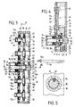
La fig. 1 est une vue en plan schématique d'un élément de construction comprenant le dispositif de serrure de l'invention.Fig. 1 is a schematic plan view of a building element comprising the lock device of the invention.
La fig. 2 est une élévation vue de face du côté extérieur de la serrure à combinaison apparente à la fig. 1.Fig. 2 is a front view elevation of the exterior side of the combination lock apparent in FIG. 1.
La fig. 3 est une coupe vue suivant la ligne III-III de la fig. 2.Fig. 3 is a section seen along line III-III of FIG. 2.
La fig. 4 est une coupe vue suivant la ligne IV-IV de la fig. 3.Fig. 4 is a section seen along the line IV-IV of FIG. 3.
La fig. 5 est une coupe schématique vue sensiblement suivant la ligne V-V de la fig. 3.Fig. 5 is a schematic section seen substantially along the line V-V of FIG. 3.
Les fig. 6, 7, 8 et 9 sont des coupes élévations partielles analogues à la fig. 4 illustrant des positions de fonctionnement particulières de la serrure.Figs. 6, 7, 8 and 9 are partial elevation sections similar to FIG. 4 illustrating particular operating positions of the lock.
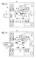
Les fig. 10, 11 et 12 à 15 sont des élévations illustrant différentes positions caractéristiques d'un monnayeur apparaissant à la fig. 2 et constituant un développement de l'invention.Figs. 10, 11 and 12 to 15 are elevations illustrating different characteristic positions of a coin mechanism appearing in fig. 2 and constituting a development of the invention.
la fig. 1 illustre de manière schématique une porte 1 articulée dans un dormant 2 et comportant une serrure 3 dont le pêne 4 est destiné à coopérer avec une gâche 5 disposée dans le dormant.fig. 1 schematically illustrates a
A titre d'exemple, la gâche 5 est dite du type à ressort c'est-à-dire qu'elle comporte un corps de retenue 6 poussé par un élément élastique 7 destiné à être comprimé par le corps 6 lorsque celui-ci est repoussé par le pêne 4 de la serrure 3. De préférence, aussi, le pêne 4 est associé à une platine protectrice 8 à laquelle il est relié rigidement et qui est destiné, notamment, à protéger ledit pêne lorsque celui-ci est engagé dans la gâche 5.By way of example, the
Il est évident que la gâche 5 pourrait être fixe et que le pêne 4 pourrait, dans ce cas, être d'un type élastique c'est-à-dire qu'il pourrait être déplaçable contre l'action d'un ressort équivalent à l'élément élastique 7 lorsque la porte 1 est pivotée dans le sens de la fermeture.It is obvious that the
La fig. 4 montre que le pêne 4 et la platine protectrice 8 sont guidés dans une plaque 9 constituant l'un des côtés d'un boîtier de serrure 10 en forme générale de parallélépipède.Fig. 4 shows that the
Le pêne 4 comporte une tête 11 qui porte la platine protectrice 8 et contre laquelle prend appui un ressort 12 de compression prenant par ailleurs appui contre la plaque 9. Le ressort 12 a pour effet de maintenir la tête 11 du pêne 4 en appui contre un coulisseau 13 guidé dans un alésage d'une douille épaulée 14 guidée dans un trou 15 du côté arrière 10a du boîtier de serrure 10.The
La douille épaulée 14 supporte à son extrémité un anneau 16 qui y est fixé rigidement et qui est guidé dans un carter 17 lui-même rapporté audit côté arrière 10a. La douille épaulée 14 est empêchée de tourner, par exemple au moyen d'un ergot 18 (fig. 3) guidé dans une lumière 19 du carter 17.The
Un ressort de compression 20 est interposé entre le côté arrière 10a du boîtier de serrure et l'anneau 16 pour tendre toujours à rapprocher l'épaulement 14a de la douille 14 de la face interne du côté arrière 10a.A
La douille épaulée 14 est enfilée à frottement doux pour pouvoir coulisser sur une partie décolleté 21a d'un bouton 21 de déverrouillage qui fait saillie du côté avant 10b du boîtier de serrure 10 en passant par un trou 22.The
De préférence, comme le montre la fig. 3, le bouton 21 est empêché de tourner par un ergot 23 porté par le côté avant 10b et engagé dans une rainure 24 de ce bouton. Le bouton 21 présente, à partir de son côté opposé à celui faisant saillie par le trou 22, un alésage 25 dans lequel est engagée une tige 26a d'un poussoir 26 guidé dans le carter 17 et accesible par une lumière 27 de ce carter.Preferably, as shown in fig. 3, the
Un ressort de compression 28 est interposé entre le poussoir 26 et l'extrémité de la partie décolletée 21a du bouton 21, ce ressort étant choisi pour présenter une raideur supérieure à celle du ressort de compression 20 décrit dans ce qui précède.A
La partie décolletée 21a du bouton 21 présente des trous 29 et 30 bien visibles aux fig. 8 et 9 dont un côté forme une rampe 29a, respectivement, 30a. Le trou 29 est aligné axialement avec le coulisseau 13 et le trou 30 est aligné avec un coulisseau 30 dont la fonction est exposée dans ce qui suit.The low-
Il est avantageux que l'extrémité des coulisseaux 13 et 31 soit conique, ou oblique selon leur forme en section, pour faciliter leur coopération avec les rampes 29a et 30a. De même, l'extrémité de la tige 26a est conique ou oblique comme illustré en 26₁ pour constituer des rampes devant coopérer avec les coulisseaux 13 et 31 guidés dans l'épaulement 14a de la douille épaulée 14.It is advantageous that the end of the
La partie décolleté 21a du bouton 21 délimite, sur ce dernier, un épaulement 21b contre lequel est fixée une plaque 32 qui s'étend sur la majeure partie de la hauteur du boîtier de serrure 10 à l'intérieur de celui-ci comme le montre en particulier la fig. 3.The
Les moyens, décrits dans ce qui précède, constituent un dispositif de confirmation et de déverrouillage destiné à fonctionner en corrélation avec des ensembles à combinaison 33 portés par le boîtier 10 et la plaque 32. Les ensembles à combinaison 33 sont identiques entre eux et leur nombre peut varier suivant le nombre de données que l'on désire devoir prendre en considération pour permettre le déverrouillage de la serrure. Dans l'exemple représenté, quatre ensembles à combinaison sont illustrés pour que l'ensemble des données corresponde à un nombre de quatre chiffres.The means, described in the foregoing, constitute a confirmation and unlocking device intended to operate in correlation with
Chaque ensemble à combinaison comporte une bague 34 reliée rigidement à la plaque 32 pour le support d'un noyau 35 formé à partie d'un bouton extérieur 36. Le noyau 35 et, par conséquent le bouton 36, sont maintenus en place, d'une part, au moyen d'une collerette 37 et, d'autre part, au moyen d'un jonc 38 prenant respectivement appui sur l'une et l'autre faces de la plaque 32. La face libre de la collerette 37 comporte des repères par exemple des chiffres ou des lettres ou d'autres données caractéristiques dont le nombre correspond à celui d'encoches 39 (fig. 5) prévues dans la bague 34 et dans lesquelles peut entrer une bille ou verrou 40 poussé par un ressort 41 peut entrer.Each combination assembly comprises a
Les repères de la collerette 37 sont visibles dans leur succession par des lumières 42 prévues dans le côté avant 10b du boîtier 10.The marks of the
Le dispositif à verrou 40, ressort 41 et encoche 39 peut être remplacé par d'autres moyens d'indexage, par exemple par un dispositif magnétique c'est-à-dire qu'un segment d'arc du noyau 35 peut présenter une polarité déterminée et que des pôles magnétiques successifs peuvent être prévus à la périphérie de la bague 34 pour que le noyau 35 puisse être amené à occuper des positions angulaires bien définies correspondant aux repères de la collerette 37.The
Le noyau 35 est prolongé, sur son côté opposé à celui formant le bouton extérieur 36, par un corps décolleté 43 engagé dans un alésage 44 coaxial d'un bouton intérieur 45 faisant saillie au-delà du côté arrière 10a du boîtier de serrure 10. Le bouton 45 est monté de même manière que le noyau 35 décrit dans ce qui précède c'est-à-dire qu'il est engagé dans une bague 34a identique à la bague 34 décrite dans ce qui précède en relation à la fig. 5 et présentant, comme l'illustre la fig. 5, des encoches 40 ou autre moyens d'indexage coopérant avec une bille ou autre verrou 40.The
Chaque bouton intérieur 45 comporte une collerette 37a analogue à la collerette 37 des boutons extérieurs 36 et portant comme ces derniers des repères correspondant à ceux de ladite collerette 37 à savoir des chiffres, des lettres ou autres données. Les repères de la collerette 37a peuvent être vus indépendamment les uns des autres par des lumières 42a identiques aux lumières 42 mais pratiquées dans le côté arrière 10a.Each
Outre ce qui précède, le bouton intérieur 45 présente une encoche 46 destinée à recevoir un doigt 47 (fig. 3) porté par le corps décolleté 43 faisant partie du bouton extérieur 36. L'alésage 44 du bouton intérieur 45 est avantageusement fermé par une pastille 48.In addition to the above, the
Dans le mode de réalisation représenté aux fig. 2, 4 et 6 à 15, le dispositif de serrure comporte un monnayeur destiné dans son ensemble par la référence 49. La commande du monnayeur est assurée par une pièce de monnaie 50 de caractéristiques précises (poids et dimension) et par une came coulissante 51 aux fig. 2, 4 et 6 à 9, Cette came étant reliée rigidement à une plaque coulissant 52. La came coulissante 51 délimite en regard du coulisseau 31 une plage de butée 53 suivie par une encoche 54, elle-même suivie par une rampe 55 (fig. 4).In the embodiment shown in FIGS. 2, 4 and 6 to 15, the lock device comprises a coin mechanism intended as a whole by the
Abstraction faite du monnayeur 49, la serrure fonctionne de la façon suivante.Apart from the
En position d'attente ou d'ouverture, les organes de la serrure occupent la position illustrée aux fig. 3 et 4 c'est-à-dire que les boutons extérieurs 36 sont escamotés dans le boîtier 10 et qu'il en est de même du pêne 4 de sorte que la porte 1 est ouverte bien qu'elle puisse être inscrite dans le dormant 2.In the standby or open position, the lock members occupy the position illustrated in FIGS. 3 and 4, that is to say that the
Il est avantageux que la platine protectrice 8 présente des parties colorées par exemple en vert et en rouge, la partie colorée en vert étant apparente par une fenëtre du boîtier lorsque le pêne est rentré pour indiquer que la porte 1 peut être manoeuvrée librement, par exemple pour donner accès à un logement situé derrière ladite porte et la partie colorée en rouge apparente lorsque le pêne 4 est sorti.It is advantageous that the
Lorsque l'utilisateur du logement pouvant être fermé par la porte 1 désire verrouiller la porte, il l'ouvre tout d'abord, ce qui donne accès aux boutons intérieurs 45 qui sont les seuls apparents ou au moins les seuls pouvant être manoeuvrés. L'utilisateur forme une combinaison de données en faisant tourner d'une mesure appropriée les boutons intérieurs 45.When the user of the housing which can be closed by the
Après l'établissement de la combinaison, l'utilisateur valide celle-ci en exerçant une poussée sur le poussoir 26 dont la tige 26a commence à écarter les coulissaux 13 et 31 par l'extrémité conique 26₁. Cela a pour effet, comme l'illustrent les fig. 4 et 6, de déplacer le pêne 4 suivant la flèche f₁ et la came coulissante 51 suivant la flèche f₂.After establishing the combination, the user validates it by exerting a push on the
Lorsque les coulisseaux 13 et 31 occupent la position illustrée à la fig. 6, ils viennent en appui contre les rampes 29a, 30a délimitant l'un des bords des trous 29, 30. L'action sur le poussoir 26 est transmise à la partie décolletée 21a du bouton 21 par le ressort 28 et, par conséquent, ledit bouton 21 est progressivement repoussé à l'extérieur du côté avant 10b du boîtier 10.When the
Le mouvement du bouton 21, dans le sens de la flèche f₃ (fig. 7 et 8), a pour effet de déplacer simultanément la plaque 32 qui en même temps repousse la came coulissante 51 puisque ladite plaque 32 coulisse le long de la rampe 55.The movement of the
Le mouvement décrit ci-dessus du poussoir 26 et du coulisseau 13 a eu pour effet de faire sortir complètement le pêne 4 contre l'action du ressort 12 qui est comprimé.The movement described above of the
Lorsqu'on cesse d'exercer une poussée sur le poussoir 26, le ressort 28 peut se détendre en ramenant le poussoir à sa position initiale, ce qui est illustré par la fig. 8. Ce dernier mouvement est sans influence sur la position du coulisseau 13 et de même sur la position du coulisseau 31 puisque ces organes reposent alors sur la surface de la partie décolletée 21a du bouton 21.When one ceases to exert a push on the
Les coulisseaux 13 et 31 étant libres sur la surface de la partie décolletée 21a, le ressort 20 de moindre raideur peut se détendre, ce qui a pour effet d'éloigner les coulisseaux 13 et 31 des trous 29, 30.The
A la position atteinte par les différents organes, telle qu'illustrée à la fig. 8, le pêne 4 est complètement sorti de sorte que la porte 1 peut être fermée en la claquant, ledit pêne agissant de façon connue sur la gâche élastique 5 qui assure son verrouillage tandis que la platine protectrice 8 empèche qu'un accès à la gâche soit possible, cette plaque montrant en outre le segment de couleur rouge.At the position reached by the various organs, as illustrated in FIG. 8, the
Lorsque la porte est fermée, les boutons intérieurs 45 ne sont plus accessibles mais les boutons extérieurs 36 font saillie du côté avant 10b du boîtier de serrure 10 et peuvent, par conséquent, être manoeuvrés de même que le bouton 21 faisant partie du dispositif de confirmation et de déverrouillage.When the door is closed, the
Il est remarquable de constater, en se référant par exemple à la fig. 3, que les boutons extérieurs 36 peuvent être tournés librement sans que la combinaison établie à partir des boutons intérieurs 45 puisse être détectée puisque, lorsque les boutons extérieurs 36 sont sortis c'est-à-dire lorsque la plaque 32 qui les porte a été amenée au voisinage du côté avant 10a du boîtier de serrure 10, comme l'illustre la fig. 8, les ergots 47 sont très éloignés des encoches 46 des boutons intérieurs.It is remarkable to note, by referring for example to FIG. 3, that the
Le ressort 20 étant détendu, la douille épaulée 14 est en butée par son épaulement 14a contre la paroi interne du côté arrière 10a du boîtier, ce qui est illustré par la fig. 8. Par conséquent, une poussée exercée sur le bouton de déverrouillage 21 ne peut pas amener les trous 29, 30 dans le plan des coulisseaux 13 et 31 car un déplacement de la plaque 32 ferait que l'un au moins des ergots 47 viendrait buter contre la face arrière des boutons intérieurs 45 sans produire aucun autre effet que la compression partielle du ressort 28 qui ramènerait par conséquent ensuite ledit bouton 21 à sa position initiale.The
En revanche, si l'utilisateur reproduit avec les boutons extérieurs 36 la combinaison initialement faite avec les boutons intérieurs 45 alors les ergots 47 sont amenés en alignement avec les encoches 46. De cette manière, une poussée exercée sur le bouton 21 de déverrouillage permet de déplacer la plaque 32 d'une mesure suffisante pour que tous les ergots 47 entrent dans l'encoche 46 qui leur correspond. Le déplacement du bouton 21 est alors suffisant pour que les trous 29a et 30a soient amenés dans le plan des coulisseaux 13 et 31 de sorte que le ressort 12 du pêne 4 qui est comprimé repousse le coulisseau 13 qui, de même le coulisseau 31, entre dans les trous 29 et 30 respectivement. Lorsqu'on cesse d'exercer une poussée suivant la flèche f₃ sur le bouton 21, le ressort 28 pousse la partie décolletée 21 et la bague épaulée 14 pour que cette bague vienne réoccuper la position illustrée aux fig. 3 et 4. Le ressort 28, qui est de plus grande raideur que le ressort 20, fait à nouveau comprimer celui-ci. Le déplacement dans le sens contraire de la flèche f₃ du bouton 21 et donc la laque 32 a pour effet de faire sortir les ergots 47 des encoches 46 de sorte que les boutons intérieurs 45 sont de nouveau disponibles pour permettre la création d'une nouvelle combinaison.On the other hand, if the user reproduces with the
Si l'usager perd la combinaison permettant de faire ouvrir la serrure. celle-ci peut alors être ouverte par une autorité compétente disposant d'une clé appropriée qui est illustrée en 56 de façon schématique à la fig. 3.If the user loses the combination allowing the lock to be opened. it can then be opened by a competent authority having an appropriate key which is illustrated at 56 schematically in FIG. 3.
La serrure est munie dans le côté arrière 10a d'une douille 57 immobilisée par une bille de verrouillage 58 ou autre organe analogue réalisé en une matière magnétique. La douille 57 est munie d'un canon à combinaison 59 pouvant être très complexe qui correspond à la combinaison d'une clé 56 qui est, par ailleurs, munie d'un embout magnétique 56a. De plus, la douille 57 comporte une came 60 disposée en regard d'une rampe 61 de la douille épaulée 14. En introduisant la clé 56 dans des trous 62, 63 du côté avant 10b et de la plaque 32 respectivement, l'embout magnétique 65a permet de soulever la bille de verrouillage 58 pour rendre possible la rotation de la douille 57 par la clé 56. La came 60 a ainsi pour effet de faire coulisser la douille épaulée 14 vers le côté avant du boîtier 10 et en appuyant sur le bouton 21 les coulisseaux 13 et 31 peuvent venir réoccuper la position illustrée à la fig. 4 pour laquelle la serrure est ouverte.The lock is provided in the
Comme exposé dans ce qui précède, le dispositif de serrure à combinaison décrit peut comporter en combinaison un ensemble monnayeur. Cet ensemble comporte un bâti 64 fixé rigidement au boîtier 10 et sur lequel sont montées des glissières 65 pour la plaque 52 décrite dans ce qui précède qui est ainsi guidée axialement de même que la came coulissante 51. La bâti 64 supporte par exemple comme représenté deux ergots fixes 66 et 67 engagés dans des boutonnières 68 et 69 de la plaque 52, ces deux lumières étant de longueur sensiblement égale.As explained in the foregoing, the combination lock device described may comprise in combination a coin operated assembly. This assembly comprises a
De son côté, la plaque 52 porte un doigt 70 destiné à coulisser dans une première rainure 71 du boîtier 64 qui présente une seconde rainure 72 dans laquelle est engagée l'extrémité d'un pion 73 également engagé dans une lumière oblongue 74 de la plaque 52. Le pion 73 est maintenu par un ressort 75 exerçant une action élastique tendant à le faire coulisser dans le sens de la flèche f₄ c'est-à-dire vers l'ergot 66. La longueur des boutonnières 68, 69 et des première et seconde rainures 71, 72 est la même alors que la longueur de la lumière oblongue 74 est plus petite pour un motif qui ressort de la description qui suit.For its part, the
Le dessin montre que la plaque 52 est constamment poussée par un ressort 76 d'un type quelconque destiné à maintenir la came coulissante 51 contre le coulisseau 31. Outre ce qui précède, la plaque 52 délimite une encoche 77 présentant un front 78 et une rampe 79. Un bonhomme à ressort 80 ou verrou analogue est porté par le bâti 64 pour coopérer avec le dessus de la plaque 52 qui délimite l'encoche 77.The drawing shows that the
La fig. 4 montre que le bâti 64 délimite un couloir 81 pour le guidage de la pièce de monnaie 50 dont les caractéristiques de dimension sont choisies pour que cette pièce 50 soit retenue par l'ergot fixe 66 et le pion 73 se trouvant dans le fond de la lumière oblongue 74 (fig. 10) lorsque la plaque 52 et, par conséquent, la came coulissante 51 sont poussées contre le coulisseau 31 alors que le dispositif de serrure est en position ouverte et que ses organes se trouvent placés de la manière illustrée par la fig. 4.Fig. 4 shows that the
Lors du début de la fermeture de la serrure, c'est-à-dire lorsque le poussoir 26 commence à faire écarter les coulisseaux 13 et 31, la plaque 52 est déplacée dans le sens de la flèche f₅ (fig. 11) contre l'action du ressort 76. La boutonnière 68 est, par conséquent, déplacée par rapport à l'ergot fixe 66 et il en est de même de la lumière oblongue 74. Le pion 73 est par suite amené dans le fond de la lumière oblongue 74 et commence à être déplacé dans le sens de la flèche f₅. Si la pièce 50 correspond au point de vue diamètre à la seule pièce pouvant être utilisée, elle intercepte alors le fond de l'encoche 77 et le front 78 en formant ainsi une rampe pour le bonhomme à ressort 80 qui est soulevé en suivant le bord périphérique de la pièce pendant que la plaque 52 continue son mouvement suivant la flèche f₅.At the start of the closing of the lock, that is to say when the
Si la pièce 50 ne présentait pas une dimension excessive ou bien elle tombait en passant entre l'ergot 66 et le pion 73, dans ce cas le bonhomme à ressort 80 viendrait buter contre le front 78 ou bien c'est la pièce elle-même qui constituerait une butée pour le bonhomme à ressort 80. Dans l'un et l'autre cas la came coulissante 51 serait immobilisée, ce qui empêcherait tout coulissement du coulisseau 31 et par conséquent bloquerait la serrure en position ouverte.If the
Lorsque la plaque 52 a été déplacée d'une mesure suffisante suivant la flèche f₅, le pion 73 est déplacé d'une mesure faisant que la pièce 50 peut tomber entre ces deux derniers organes, ce qui est illustré par la fig. 12 qui fait apparaître aussi que la pièce 50 illustrée en trait plein vient alors en appui sur le doigt 70 et l'ergot fixe 67.When the
En fin de fermeture de la serrure c'est-à-dire lorsque le pêne 4 et la came coulissante 51 se trouvent dans la position illustrée par la fig. 8, la pièce 50 est maintenue sur l'ergot fixe 67 et le doigt 70 porté par la plaque 52. Dans cette position, l'ergot fixe 67 se trouve dans le fond de la boutonnière 69, tandis que le doigt 70 se trouve dans le fond opposé de la première rainure 71, le bonhomme à ressort 80 reposant alors sur le côté supérieur de la plaque 52.At the end of the closing of the lock, that is to say when the
Lorsque la serrure est de nouveau en cours d'ouverture après exécution de la combinaison à partir des boutons extérieurs 36 faisant saillie du côté avant 10b du boîtier, la plaque 52 est poussée par le ressort 76 dans le sens de la flèche f₆ (fig. 14) de sorte que le bonhomme à ressort 80 tombe à nouveau dans l'encoche 77 (fig. 14) puis ce bonhomme à ressort est progressivement rétracté lorsqu'il suit la rampe 79 (fig. 15).When the lock is opened again after execution of the combination from the buttons outer 36 projecting from the
En fin de course de retour suivant la flèche f₆ de la plaque 52, le doigt 70 porté par la plaque est suffisamment écarté de l'ergot fixe 67 porté par le bâti 64 pour que la pièce 50 puisse tomber en dessous de ladite plaque 52 et être récupérée soit dans un boîtier de réserve, soit directement par l'utilisateur du logement fermé par la porte 1.At the end of the return stroke along the arrow f₆ of the
Il va de soi que les différentes parties constitutives de la serrure peuvent être réalisées en différentes matières en particulier dans des réalisations économiques, par exemple lorsque la serrure est mise en oeuvre pour la fermeture de vestiaires ou analogues, les ensembles à combinaison constitués par les boutons intérieurs 45 et extérieurs 36 ainsi que les bouton 21, douille épaulée 14 et autres du dispositif de confirmation et de déverrouillage peuvent être fabriqués en matière synthétique injectée pour rendre possible une fabrication de grande série particulièrement économique bien que la sécurité apportée par la serrure demeure très satisfaisante puisque les manoeuvres réalisables à partir du côté avant 10b du boîtier ne permettent pas de déterminer la combinaison réalisée à partir des boutons intérieurs et que les boutons extérieurs sont escamotés tant que la serrure n'est pas fermée.It goes without saying that the various constituent parts of the lock can be made of different materials, in particular in economical embodiments, for example when the lock is used for closing locker rooms or the like, the combination sets constituted by the buttons inside 45 and outside 36 as well as the
L'invention n'est as limitée aux exemples de réalisation représentés et décrits en détail, car diverses modifications peuvent y être apportées sans sortir de son cadre. En particulier la serrure peut être mise en oeuvre sans le monnayeur et, dans ce cas, le coulisseau 31, la came coulissante 51 et les moyens décrits ci-dessus, propres au monnayeur, peuvent être supprimés. De même, le côté avant du boîtier 10 peut être prolongé par un flasque 10₁ (fig. 2) venant recouvrir la feuillure du dormant 2 pour empècher tout accès au pêne 4 et à la gâche 5.The invention is not limited to the embodiments shown and described in detail, because various modifications can be made without departing from its scope. In particular, the lock can be implemented without the coin mechanism and, in this case, the
Claims (16)
Applications Claiming Priority (2)
| Application Number | Priority Date | Filing Date | Title |
|---|---|---|---|
| FR9012436 | 1990-10-09 | ||
| FR9012436A FR2667644B1 (en) | 1990-10-09 | 1990-10-09 | COMBINATION LOCK DEVICE. |
Publications (1)
| Publication Number | Publication Date |
|---|---|
| EP0480823A1 true EP0480823A1 (en) | 1992-04-15 |
Family
ID=9401055
Family Applications (1)
| Application Number | Title | Priority Date | Filing Date |
|---|---|---|---|
| EP91402688A Withdrawn EP0480823A1 (en) | 1990-10-09 | 1991-10-08 | Combination lock device |
Country Status (2)
| Country | Link |
|---|---|
| EP (1) | EP0480823A1 (en) |
| FR (1) | FR2667644B1 (en) |
Cited By (4)
| Publication number | Priority date | Publication date | Assignee | Title |
|---|---|---|---|---|
| ES2079259A2 (en) * | 1992-06-19 | 1996-01-01 | Quero Vicente Navarro | Totally mechanical, key-less, high security lock. |
| FR2735172A1 (en) * | 1995-06-12 | 1996-12-13 | Palladino Lucien | Combination lock in various sizes for drawers, cupboards, safes, hand brake locks, car anti theft devices |
| FR2747421A1 (en) * | 1996-04-16 | 1997-10-17 | Const Ind De Meubles Metalliqu | CODING AND CODING LOCATION DEVICE FOR FURNITURE LOCKS AND THE LIKE |
| ES2128889A1 (en) * | 1995-02-28 | 1999-05-16 | Quero Vicente Navarro | Totally mechanical high-security keyless lock |
Families Citing this family (1)
| Publication number | Priority date | Publication date | Assignee | Title |
|---|---|---|---|---|
| FR2719864B1 (en) * | 1994-05-10 | 1996-06-21 | Ronis Sa | Security pass lock. |
Citations (2)
| Publication number | Priority date | Publication date | Assignee | Title |
|---|---|---|---|---|
| GB191318757A (en) * | 1913-08-18 | 1914-04-02 | Thomas Arthur White | Improvements in Code or Combination Locks. |
| US4220023A (en) * | 1978-10-02 | 1980-09-02 | Beede Jefts G | Combination lock |
-
1990
- 1990-10-09 FR FR9012436A patent/FR2667644B1/en not_active Expired - Lifetime
-
1991
- 1991-10-08 EP EP91402688A patent/EP0480823A1/en not_active Withdrawn
Patent Citations (2)
| Publication number | Priority date | Publication date | Assignee | Title |
|---|---|---|---|---|
| GB191318757A (en) * | 1913-08-18 | 1914-04-02 | Thomas Arthur White | Improvements in Code or Combination Locks. |
| US4220023A (en) * | 1978-10-02 | 1980-09-02 | Beede Jefts G | Combination lock |
Cited By (5)
| Publication number | Priority date | Publication date | Assignee | Title |
|---|---|---|---|---|
| ES2079259A2 (en) * | 1992-06-19 | 1996-01-01 | Quero Vicente Navarro | Totally mechanical, key-less, high security lock. |
| ES2128889A1 (en) * | 1995-02-28 | 1999-05-16 | Quero Vicente Navarro | Totally mechanical high-security keyless lock |
| FR2735172A1 (en) * | 1995-06-12 | 1996-12-13 | Palladino Lucien | Combination lock in various sizes for drawers, cupboards, safes, hand brake locks, car anti theft devices |
| FR2747421A1 (en) * | 1996-04-16 | 1997-10-17 | Const Ind De Meubles Metalliqu | CODING AND CODING LOCATION DEVICE FOR FURNITURE LOCKS AND THE LIKE |
| EP0802290A1 (en) * | 1996-04-16 | 1997-10-22 | Construction Industrielle de Meubles Métalliques CIMM | Encoding device and code-identifying device for furniture locks or the same |
Also Published As
| Publication number | Publication date |
|---|---|
| FR2667644B1 (en) | 1992-12-11 |
| FR2667644A1 (en) | 1992-04-10 |
Similar Documents
| Publication | Publication Date | Title |
|---|---|---|
| CH642137A5 (en) | SAFETY LOCK WITH ROCKER PIN. | |
| EP2179117B1 (en) | Locking device | |
| FR2504180A1 (en) | SLEEPING LATCH | |
| CH378184A (en) | Operating mechanism for combination locks | |
| WO2021148747A1 (en) | Luggage-type leather article | |
| EP0749135B1 (en) | Control button with latch, particularly for controlling an electrical component | |
| FR2648855A1 (en) | UNIVERSAL ASSEMBLY FOR TOP AND BOTTOM LOCKS, IN VERTICAL BAR OUTPUT DEVICES, AND TOP AND BOTTOM LOCKS FOR SUCH DEVICES | |
| EP0227507B1 (en) | Safety lock, object, especially a piece of luggage, and an installation for applying it | |
| EP0480823A1 (en) | Combination lock device | |
| FR2738864A1 (en) | Combination lock, e.g. for luggage with sliding clasp fasteners | |
| CH689338A5 (en) | Pocket watch having release mechanism for two covers | |
| EP0294276B1 (en) | Disc combination lock with automatic scrambling on closing | |
| CH680521A5 (en) | ||
| EP4093235B1 (en) | Leathercraft article of the luggage type | |
| CA1247878A (en) | Combination lock, namely for safes | |
| FR2815067A1 (en) | Lock security cylinder comprises double stator block, key bit and barrel rotor in first stator and operating button at outer end of second stator and declutchable transmission means | |
| FR2918690A1 (en) | Coded assist handle for e.g. door of building, has locking unit i.e. key, moving between marking position along which unit guides shaft to engage with rod and blocking position along which unit immobilizes shaft to disengage from rod | |
| FR2696776A1 (en) | Cylinder lock with dynamic key - includes sliding locking ring which is biased towards front of lock by spring ,this ring preventing any rotation of barrel, even if notches of key correspond to those of cylinder | |
| FR2552146A1 (en) | Security lock | |
| EP0368703A1 (en) | Lock with disc tumblers | |
| FR2513296A1 (en) | SAFETY LOCK, IN PARTICULAR OF THE TYPE WITH MULTIPLE CLOSURE POINTS | |
| FR3106475A1 (en) | Luggage type leather goods | |
| EP0367649A1 (en) | Safety lock with disc tumblers | |
| BE519352A (en) | ||
| EP0071692A1 (en) | Barrel lock with two lock positions |
Legal Events
| Date | Code | Title | Description |
|---|---|---|---|
| PUAI | Public reference made under article 153(3) epc to a published international application that has entered the european phase |
Free format text: ORIGINAL CODE: 0009012 |
|
| 17P | Request for examination filed |
Effective date: 19911011 |
|
| AK | Designated contracting states |
Kind code of ref document: A1 Designated state(s): AT BE CH DE DK ES GB GR IT LI LU NL SE |
|
| 17Q | First examination report despatched |
Effective date: 19930121 |
|
| STAA | Information on the status of an ep patent application or granted ep patent |
Free format text: STATUS: THE APPLICATION IS DEEMED TO BE WITHDRAWN |
|
| 18D | Application deemed to be withdrawn |
Effective date: 19930602 |