EP0186827A2 - Plastikumhüllung zur starren Verbindung von Metallsockel und Glaskolben einer Lampe - Google Patents
Plastikumhüllung zur starren Verbindung von Metallsockel und Glaskolben einer Lampe Download PDFInfo
- Publication number
- EP0186827A2 EP0186827A2 EP85115806A EP85115806A EP0186827A2 EP 0186827 A2 EP0186827 A2 EP 0186827A2 EP 85115806 A EP85115806 A EP 85115806A EP 85115806 A EP85115806 A EP 85115806A EP 0186827 A2 EP0186827 A2 EP 0186827A2
- Authority
- EP
- European Patent Office
- Prior art keywords
- skirt
- lamp
- plastics
- metallic base
- glass envelope
- Prior art date
- Legal status (The legal status is an assumption and is not a legal conclusion. Google has not performed a legal analysis and makes no representation as to the accuracy of the status listed.)
- Granted
Links
- 239000004033 plastic Substances 0.000 title claims abstract description 65
- 229920003023 plastic Polymers 0.000 title claims abstract description 65
- 239000011521 glass Substances 0.000 title claims abstract description 38
- 230000000295 complement effect Effects 0.000 claims abstract description 11
- 239000000463 material Substances 0.000 claims description 8
- 239000004695 Polyether sulfone Substances 0.000 claims description 3
- 239000004697 Polyetherimide Substances 0.000 claims description 3
- 229920006393 polyether sulfone Polymers 0.000 claims description 3
- 239000004642 Polyimide Substances 0.000 claims description 2
- 229920001601 polyetherimide Polymers 0.000 claims description 2
- 229920001721 polyimide Polymers 0.000 claims description 2
- 229910000679 solder Inorganic materials 0.000 description 10
- 239000002184 metal Substances 0.000 description 7
- 230000013011 mating Effects 0.000 description 6
- 238000000034 method Methods 0.000 description 4
- 229910001369 Brass Inorganic materials 0.000 description 3
- 239000010951 brass Substances 0.000 description 3
- 238000007373 indentation Methods 0.000 description 2
- 229920004738 ULTEM® Polymers 0.000 description 1
- 229920004695 VICTREX™ PEEK Polymers 0.000 description 1
- 230000015572 biosynthetic process Effects 0.000 description 1
- 229910052736 halogen Inorganic materials 0.000 description 1
- 150000002367 halogens Chemical class 0.000 description 1
- 238000002347 injection Methods 0.000 description 1
- 239000007924 injection Substances 0.000 description 1
- 239000012212 insulator Substances 0.000 description 1
- WABPQHHGFIMREM-UHFFFAOYSA-N lead(0) Chemical compound [Pb] WABPQHHGFIMREM-UHFFFAOYSA-N 0.000 description 1
- 238000002844 melting Methods 0.000 description 1
- 230000008018 melting Effects 0.000 description 1
- 238000000465 moulding Methods 0.000 description 1
- 229920000620 organic polymer Polymers 0.000 description 1
- 229920006162 poly(etherimide sulfone) Polymers 0.000 description 1
- 230000035939 shock Effects 0.000 description 1
Images

Classifications
-
- H—ELECTRICITY
- H01—ELECTRIC ELEMENTS
- H01K—ELECTRIC INCANDESCENT LAMPS
- H01K1/00—Details
- H01K1/42—Means forming part of the lamp for the purpose of providing electrical connection, or support for, the lamp
- H01K1/46—Means forming part of the lamp for the purpose of providing electrical connection, or support for, the lamp supported by a separate part, e.g. base, cap
-
- H—ELECTRICITY
- H01—ELECTRIC ELEMENTS
- H01J—ELECTRIC DISCHARGE TUBES OR DISCHARGE LAMPS
- H01J5/00—Details relating to vessels or to leading-in conductors common to two or more basic types of discharge tubes or lamps
- H01J5/50—Means forming part of the tube or lamps for the purpose of providing electrical connection to it
- H01J5/54—Means forming part of the tube or lamps for the purpose of providing electrical connection to it supported by a separate part, e.g. base
- H01J5/58—Means for fastening the separate part to the vessel, e.g. by cement
- H01J5/60—Means for fastening the separate part to the vessel, e.g. by cement for fastening by mechanical means
Definitions
- This invention relates to electric lamps having a plastics skirt and, more particularly, to an organic polymer or plastics skirt formed of material capable of withstanding high temperatures and having means for engaging and fixing the plastics skirt to a glass envelope and a metallic base both of the electric lamp.
- Plastics skirts are known as a replacement of metallic collars in the lamp art. Replacement plastics skirts provide the means for reducing or even eliminating an arc problem related to metal-to-glass insulated screw bases of lamps. Many lamps, particularly high voltage lamps, operate at high voltage potentials and arcing conditions between the metal base and the metallic and glass insulated collar are a possible failure mode of the lamp. The plastics skirt provides a means to substantially reduce these possible arc problems in addition to reducing any shock hazard of the collar of the lamp.
- One such plastics skirt is described in a technical article entitled "Lamp Circuitry Collar" by A. Smetana of GE Lighting Business Group of Ohio, published in the May 1983 plastics world magazine.
- the plastics skirt of Smetana rigidly affixes to both the glass bulb and to the metallic base of the lamp.
- the rigid affixation of the plastics skirt of Smetana prevents the skirt from rotating on the bulb during unscrewing.
- the non-rotation is provided by "staking" which is accomplished by injecting molten solder through two small holes in opposite sides of the plastic skirt and into small depressions in the glass envelope so as to form solder locks. This injection molten solder process forming the solder locks while performing its desired non-rotation of the plastics skirt has disadvantages.
- solder locks are relatively slow processes requiring time for the first solder to set or freeze, then a 180 degree rotation of the skirt and glass to form the second solder lock and then allowing for its related setting time.
- the related operation temperature for the solder locks is that of the molten high temperature of solder having a melting temperature of about 495 degrees Fahrenheit.
- an object of the present invention is to provide means formed as an integral part of the plastics skirt so as to rigidly affix the plastics skirt to both the glass envelope and the metal base all of the lamp.
- This invention is directed to a lamp having a plastics skirt that rigidly engages and affixes to a glass envelope and to a metallic base both of the lamp.
- the lamp comprises an outer glass envelope having at least one dimple at its lower portion and a light source disposed within the outer envelope.
- the lamp further comprises a metallic base having at least one dimple at its open upper portion.
- the lamp further has a plastics skirt having means for complementary engaging and affixing to the dimples of each of the glass envelope and the metallic base. The complementary engaging and affixing of the plastics skirt to the glass envelope is accomplished by ramp-like semi-flexible extensions integrally formed in the plastics skirt which fit into and engage an inner portion of the dimple of the glass envelope.
- FIG. 1 illustrates a parabolic aluminized reflector (PAR) in accordance with one embodiment of the present invention.
- the PAR lamp 10 has an outer envelope 12 having at least one dimple indentation at its lower rim portion to be described hereinafter with regard to FIG. 6.
- the inner and outer surfaces are appropriately contoured and coated in manner well known in the PAR lamp art.
- Lamp 10 has a light source 14 shown in phantom disposed within the outer envelope 12.
- the light source has a central portion located at the focal point of the lamp 10 and may be an incandescent filament or a halogen light source.
- the lamp 10 further has a metallic base 16 preferably of a brass material and has at least one dimple indentation at its upper portion to be described hereinafter with regard to FIG. 3.
- the metallic base 16 and also the outer envelope 12 are both connected to a plastics skirt 18 having means for complementary engaging and affixing to the dimples of the glass envelope and the metallic base.
- the plastics skirt 18, which is of primary importance to the present invention, provides for the complementary engaging and fastening of the plastics skirt 18 to glass envelope by ramp-like extensions integrally formed into the plastics skirt which fit into and engage an inner portion of the dimples of the glass envelope. The ramp-like extensions provide snap-lock engagement of the glass envelope to the plastics skirt.
- the plastics skirt 18 preferably has four slots which embrace the outer envelope 12 and two of which are shown as 20 and 22 in FIG. 1. The slots provide assistance in flexing to the circular cross-section of the plastics skirt 18 during the assembly of the plastics skirt 18 to the glass envelope 12.
- the plastics skirt 18 is further shown in FIG. 2.
- FIG. 2 shows the lower or shank portion of the plastics skirt 18 as having two partial screw thread members 24 and 26 molded into the shank portion of the plastics skirt 18.
- the partial screw threads 24 and 26 are selected to have dimensions to match the internal rolled thread of the screw type metallic member 16 and provide tight engagement between the rim of the screw member 16 and the shoulder of the shank portion of the skirt 18.
- the shank portion of skirt 18 has a diameter selected to have dimensions which matches the minor internal thread diameter of the metallic base 16 so as to improve the lateral support of the base 16 and skirt 18 when so mated.
- the shank portion of skirt 18 has a conical shape which fits closely into the interior cone dome shape of the metal base 16.
- the conical shape of the skirt shank serves an important feature of the present invention, that being supporting the cone dome of the base shell 16 so as to substantially prevent any crushing action of the shell 16 when the shell 16 is screwed into a complementary electrical socket. The crushing action may otherwise be present given the large moment arm created by the relative large bulb diameter of the PAR lamp.
- This conical shape also allows for a reduction in the gauge of the metal of the screw 16 yielding benefits of reduced cost.
- the shank portion of the plastics skirt 18 has at two locations 180 degrees apart from each other, two essentially symmetrical indents 28 and 30 which are molded into the plastics skirt 18. These indents 28 and 30 receive and are matched to dimples 32 and 34 shown in FIG. 3 as located in the upper end of the base 16.
- FIG. 3 shows the base as also having a glass insulator 36, a brass eyelet 38, and button-like member 40.
- the plastics skirt 18 may also have a cutout 42 to allow the exit of a lead wire 44 of lamp 10 to be connected to the base 16 by appropriate means such as a weld 46.
- the dimples 32 and 34 of FIG. 3 are formed by staking, pinning, or other similar processes into the base 16 after assembly of the base 16 to the skirt 18. The dimples 32 and 34 engage the indents 28 and 30 of the skirt 18 which are shown in FIG. 3 in phantom.
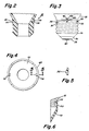
- FIG. 4 shows a top view of the plastics skirt 18 as having an an outer rim 48 and contoured side walls 50 having a shape as that shown in FIG. 1.
- the plastic skirt 18 has integrally formed therein ramp-like extensions 52 and 54 that fit into and engage the inner portions of dimples 56 and 58 (not shown) of the glass envelope.
- the preferred location of the ramp-like extensions 52 and 54 below the top surface of the skirt 18 along lines 5-5 of FIG. 4, is shown in a sectional view of the ramp-like extension 54 in FIG.
- FIG. 6 is a cross-sectional view showing the ramp-like extension 54 fitting into and engaging the inner portion of the dimple 56 of the glass envelope 12.
- the dimple 56 is formed into the lower rim portion of the glass envelope during its molding process.
- the ramp-like extensions 52 and 54 integrally formed into the skirt 18 may all be formed of a plastics material polyetherimide having a tradename Ultem and which is available from the Plastics Department of the General Electric Company of Pittsfield, Mass.
- the plastics material may also be a polyethersulfone material available as Victrex from ICI Americas.
- the skirt 18 formed from either of the polyetherimide or polyethersulfone material is capable of withstanding high temperatures in a range of about 329 to 426 degrees Fahrenheit. Further, for application temperatures of the skirt 18 up to 525 degrees Fahrenheit, plastics such as poly (amide-imide) may be used and are available from Amoco Chemicals Co. Still further, plastics such as polyimide available from the companies of DuPont and Upjohn may be used for application of the skirt 18 for temperatures in the range of about 530 to about 680 degrees Fahrenheit. The plastics skirt 18 provides sufficient flexing so that the assembly of the skirt 18 to envelope 12 does not permanently deform either the skirt 18 or its ramp-like extensions 52 and 54.
- the amount of flexing of the skirt 18 without permanent deformation, given a desired height of the ramped extensions 52 and 54, depends on the length, width and section modulus of the slotted portion integral with the ramp extensions 52 and 54 and the flexural strength of the material of the skirt 18. Such calculations are well-known in the art.
- the plastics skirt 18 was mated and connected to both the metallic base 16 and to the glass outer envelope 12.
- the assembled lamp was then subjected to a torque-like force equivalent to that encountered during the screwing of the lamp 10 into an appropriate electrical socket without causing any substantial rotation between any of the skirt 18 glass envelope 12 or metallic screw 16 member.
- the plastics skirt 18 may provide a collar type housing for lodging electrical components for high pressure metal vapor lamps.
- the skirt 18 may be provided for an improved incandescent type lamp as a housing for lodging electrical components.
- the present invention has described the glass envelope and metal screw base as each having two dimples engaged and affixed to the plastics skirt, the practice of the invention contemplates the matching of the plastics skirt to one or more than two dimples of each of the glass envelope and metal screw base.
Applications Claiming Priority (2)
| Application Number | Priority Date | Filing Date | Title |
|---|---|---|---|
| US681742 | 1984-12-14 | ||
| US06/681,742 US4658178A (en) | 1984-12-14 | 1984-12-14 | Plastics skirt for rigidly interconnecting metallic base and glass envelope of a lamp |
Publications (3)
| Publication Number | Publication Date |
|---|---|
| EP0186827A2 true EP0186827A2 (de) | 1986-07-09 |
| EP0186827A3 EP0186827A3 (en) | 1988-11-17 |
| EP0186827B1 EP0186827B1 (de) | 1991-02-27 |
Family
ID=24736591
Family Applications (1)
| Application Number | Title | Priority Date | Filing Date |
|---|---|---|---|
| EP85115806A Expired EP0186827B1 (de) | 1984-12-14 | 1985-12-11 | Plastikumhüllung zur starren Verbindung von Metallsockel und Glaskolben einer Lampe |
Country Status (4)
| Country | Link |
|---|---|
| US (1) | US4658178A (de) |
| EP (1) | EP0186827B1 (de) |
| JP (1) | JPS61153941A (de) |
| DE (1) | DE3581913D1 (de) |
Cited By (1)
| Publication number | Priority date | Publication date | Assignee | Title |
|---|---|---|---|---|
| EP0422936A2 (de) * | 1989-10-13 | 1991-04-17 | General Electric Company | Verbesserte Herstellung einer kompakten Reflektorlampe |
Families Citing this family (10)
| Publication number | Priority date | Publication date | Assignee | Title |
|---|---|---|---|---|
| US4634648A (en) * | 1985-07-05 | 1987-01-06 | Xerox Corporation | Electrophotographic imaging members with amorphous carbon |
| US4982132A (en) * | 1989-08-01 | 1991-01-01 | Gte Products Corporation | Reflector lamp assembly utilizing reflector that snaps into connector |
| US5367219A (en) * | 1991-11-18 | 1994-11-22 | U.S. Philips Corporation | Electric reflector lamp for use with IEC standard |
| US5568009A (en) * | 1994-12-29 | 1996-10-22 | Philips Electronics North America Corporation | Electric lamp having a lamp cap with solder-free connections |
| US5747919A (en) * | 1994-12-29 | 1998-05-05 | Philips Electronics North America Corporation | Electric lamp having a hybrid skirted lamp base |
| US6255763B1 (en) * | 1999-10-12 | 2001-07-03 | Osram Sylvania Inc. | Lamp base with flexible sidewall |
| WO2003081625A1 (en) * | 2002-03-21 | 2003-10-02 | Federal-Mogul Corporation | High temperature lamp |
| JP2007520855A (ja) * | 2003-10-30 | 2007-07-26 | コーニンクレッカ フィリップス エレクトロニクス エヌ ヴィ | キー機能付口金を具えるランプ及びかかるランプを製造する方法 |
| US7270453B2 (en) * | 2004-12-21 | 2007-09-18 | General Electric Company | Heat resistant plastic lamp components and methods of forming |
| CN105609393A (zh) * | 2016-03-14 | 2016-05-25 | 海宁虹新电器有限公司 | 一种厚玻壳灯泡 |
Citations (2)
| Publication number | Priority date | Publication date | Assignee | Title |
|---|---|---|---|---|
| GB688491A (en) * | 1950-06-21 | 1953-03-11 | Gen Electric Co Ltd | Improvements in or relating to electric devices, especially lamps, having capped vitreous envelopes |
| EP0096441A2 (de) * | 1982-06-05 | 1983-12-21 | Philips Patentverwaltung GmbH | Elektrische Lampe mit einem hülsenförmigen Sockel |
Family Cites Families (5)
| Publication number | Priority date | Publication date | Assignee | Title |
|---|---|---|---|---|
| GB339927A (de) * | 1929-05-18 | 1930-12-18 | The General Electric Company Limited | |
| US3746906A (en) * | 1971-08-10 | 1973-07-17 | Gen Electric | Adapter base for electric lamp |
| US4427255A (en) * | 1979-11-14 | 1984-01-24 | General Electric Company | Plastic based glass halogen lamp |
| NL7909231A (nl) * | 1979-12-21 | 1981-07-16 | Philips Nv | Lamp/reflektoreenheid. |
| JPS5715471A (en) * | 1980-07-02 | 1982-01-26 | Hitachi Ltd | Junction type field effect semiconductor device and manufacture thereof |
-
1984
- 1984-12-14 US US06/681,742 patent/US4658178A/en not_active Expired - Fee Related
-
1985
- 1985-12-11 EP EP85115806A patent/EP0186827B1/de not_active Expired
- 1985-12-11 DE DE8585115806T patent/DE3581913D1/de not_active Expired - Fee Related
- 1985-12-13 JP JP60279423A patent/JPS61153941A/ja active Pending
Patent Citations (2)
| Publication number | Priority date | Publication date | Assignee | Title |
|---|---|---|---|---|
| GB688491A (en) * | 1950-06-21 | 1953-03-11 | Gen Electric Co Ltd | Improvements in or relating to electric devices, especially lamps, having capped vitreous envelopes |
| EP0096441A2 (de) * | 1982-06-05 | 1983-12-21 | Philips Patentverwaltung GmbH | Elektrische Lampe mit einem hülsenförmigen Sockel |
Non-Patent Citations (1)
| Title |
|---|
| PLASTICS WORLD, May 1984, page 54; "Lamp circuitry collar" * |
Cited By (2)
| Publication number | Priority date | Publication date | Assignee | Title |
|---|---|---|---|---|
| EP0422936A2 (de) * | 1989-10-13 | 1991-04-17 | General Electric Company | Verbesserte Herstellung einer kompakten Reflektorlampe |
| EP0422936A3 (en) * | 1989-10-13 | 1991-08-21 | General Electric Company | Improved compact reflector lamp unit construction |
Also Published As
| Publication number | Publication date |
|---|---|
| JPS61153941A (ja) | 1986-07-12 |
| DE3581913D1 (de) | 1991-04-04 |
| EP0186827B1 (de) | 1991-02-27 |
| EP0186827A3 (en) | 1988-11-17 |
| US4658178A (en) | 1987-04-14 |
Similar Documents
| Publication | Publication Date | Title |
|---|---|---|
| EP0186827B1 (de) | Plastikumhüllung zur starren Verbindung von Metallsockel und Glaskolben einer Lampe | |
| US5189339A (en) | Fluorescent lamp assemblies | |
| US5119282A (en) | Reflector lamp assembly utilizing lens that snaps into reflector | |
| US20070267956A1 (en) | Lamp Comprising a Base That is Mounted Without Cement | |
| US5747919A (en) | Electric lamp having a hybrid skirted lamp base | |
| JPH07169313A (ja) | ランプホルダ | |
| JP4746386B2 (ja) | くさび形ベースランプのためのセンタリングリングを備えるソケット | |
| US20030209963A1 (en) | Lamp assembly and method of manufacture | |
| US5105119A (en) | Electric lamp having a pressure molded base | |
| CA2189602C (en) | Electric lamp with a variably keyed base | |
| US4982132A (en) | Reflector lamp assembly utilizing reflector that snaps into connector | |
| US5386173A (en) | One-piece thermally resistant gimbal device for a replaceable headlamp bulb | |
| CA2083013A1 (en) | Electric reflector lamp | |
| US4982131A (en) | Reflector lamp assembly utilizing lamp capsule that snaps directly into reflector | |
| US4789920A (en) | Lamp and base assembly, particularly for association with an automotive head lamp reflector | |
| US5997354A (en) | Plastic housing and base construction especially for compact fluorescent lamps and electronic operating units thereof | |
| US4536676A (en) | Lamp assembly | |
| US5751105A (en) | Assembly arrangement for a compact fluorescent lamp | |
| US4604553A (en) | Baseless incandescent lamp | |
| US3001164A (en) | Rotatable base for fluorescent lamps | |
| HU195034B (en) | Electric lamp with improved head and method for making said lamp | |
| KR950009655Y1 (ko) | 세멘트를 사용치 않는 램프 및 베이스 결합장치 | |
| US775689A (en) | Base for incandescent lamps. | |
| US6848811B2 (en) | Reflector lamp | |
| EP0200199A2 (de) | Elektrische Lampe mit selbstaufstellendem Gestellunterteil |
Legal Events
| Date | Code | Title | Description |
|---|---|---|---|
| PUAI | Public reference made under article 153(3) epc to a published international application that has entered the european phase |
Free format text: ORIGINAL CODE: 0009012 |
|
| AK | Designated contracting states |
Kind code of ref document: A2 Designated state(s): BE DE FR GB NL |
|
| PUAL | Search report despatched |
Free format text: ORIGINAL CODE: 0009013 |
|
| AK | Designated contracting states |
Kind code of ref document: A3 Designated state(s): BE DE FR GB NL |
|
| 17P | Request for examination filed |
Effective date: 19890511 |
|
| 17Q | First examination report despatched |
Effective date: 19890821 |
|
| GRAA | (expected) grant |
Free format text: ORIGINAL CODE: 0009210 |
|
| AK | Designated contracting states |
Kind code of ref document: B1 Designated state(s): BE DE FR GB NL |
|
| PG25 | Lapsed in a contracting state [announced via postgrant information from national office to epo] |
Ref country code: NL Effective date: 19910227 Ref country code: BE Effective date: 19910227 |
|
| REF | Corresponds to: |
Ref document number: 3581913 Country of ref document: DE Date of ref document: 19910404 |
|
| NLV1 | Nl: lapsed or annulled due to failure to fulfill the requirements of art. 29p and 29m of the patents act | ||
| EN | Fr: translation not filed | ||
| PG25 | Lapsed in a contracting state [announced via postgrant information from national office to epo] |
Ref country code: FR Effective date: 19910719 |
|
| PG25 | Lapsed in a contracting state [announced via postgrant information from national office to epo] |
Ref country code: GB Effective date: 19911211 |
|
| PLBE | No opposition filed within time limit |
Free format text: ORIGINAL CODE: 0009261 |
|
| STAA | Information on the status of an ep patent application or granted ep patent |
Free format text: STATUS: NO OPPOSITION FILED WITHIN TIME LIMIT |
|
| 26N | No opposition filed | ||
| GBPC | Gb: european patent ceased through non-payment of renewal fee | ||
| PG25 | Lapsed in a contracting state [announced via postgrant information from national office to epo] |
Ref country code: DE Effective date: 19920901 |
|
| REG | Reference to a national code |
Ref country code: FR Ref legal event code: ST |