EP0185484B1 - Système d'éléments de structure formant leur propre emballage pour l'entreposage et le transport et assemblage de ces éléments - Google Patents
Système d'éléments de structure formant leur propre emballage pour l'entreposage et le transport et assemblage de ces éléments Download PDFInfo
- Publication number
- EP0185484B1 EP0185484B1 EP19850308765 EP85308765A EP0185484B1 EP 0185484 B1 EP0185484 B1 EP 0185484B1 EP 19850308765 EP19850308765 EP 19850308765 EP 85308765 A EP85308765 A EP 85308765A EP 0185484 B1 EP0185484 B1 EP 0185484B1
- Authority
- EP
- European Patent Office
- Prior art keywords
- perimetrical
- joists
- members
- package
- portions
- Prior art date
- Legal status (The legal status is an assumption and is not a legal conclusion. Google has not performed a legal analysis and makes no representation as to the accuracy of the status listed.)
- Expired - Lifetime
Links
Images
Classifications
-
- E—FIXED CONSTRUCTIONS
- E04—BUILDING
- E04B—GENERAL BUILDING CONSTRUCTIONS; WALLS, e.g. PARTITIONS; ROOFS; FLOORS; CEILINGS; INSULATION OR OTHER PROTECTION OF BUILDINGS
- E04B1/00—Constructions in general; Structures which are not restricted either to walls, e.g. partitions, or floors or ceilings or roofs
- E04B1/343—Structures characterised by movable, separable, or collapsible parts, e.g. for transport
- E04B1/34315—Structures characterised by movable, separable, or collapsible parts, e.g. for transport characterised by separable parts
Definitions
- This invention relates to new and useful improvements in pre-fabricated structures and is an improvement on my corresponding Canadian Patent No. 1,018,719.
- the present structure allows pre-manufacturing or pre-fabrication of relatively large floor/roof structures and its transportation in a relatively small sized, self-containing package with usable space therein for storing other portions of the structure such as perimetrical beams, vertical supports and the like.
- the structure may be erected readily and easily from the package and of course can be easily dismantled and transported again in the self-containing component package of minimum size because the floor/roof components may be connected with the others in the structure from the inside thereof while the portions of these components may be connected in a package for transportation, from outside of the package.
- the present invention provides a floor/ceiling package of the aforesaid kind which includes at least two portions, means for detachably securing said portions together along a common junction line between the or each two adjacent portions to form a floor or ceiling unit, the or each junction line extending parallel to said joists, each portion having a support joist at the common junction line for selectively securing said portions together, said portions being nestable one within the other, to form said package when separated, one of said portions being reversed vertically through 180° relative to an adjacent portion and placed whereby said joists of one portion are nested against said corresponding joists of the other adjacent portion in side-by-side relationship so that said planar panels form upper and lower enclosure surfaces of said package, and means to detachably secure said portions together to form said package.
- the small sized component package is readily transportable anywhere and in any climate because it is self-contained and the nesting construction of the two portions of each floor/roof component adds strength to the package.
- the structures are rapidly erected with relatively unskilled labour regardless of the size and volume required.
- a square or rectangular floor/roof component of any size with its shorter side being larger than the maximum load width transportable on highways, is split into two or more portions so that this side does not exceed the maximum load width permitted.
- Each floor/roof component package includes at least two portions of the structure, one placed in nesting relationship with the other and both creating a self-closing surface on the upper and lower sides enclosed by their roof or floor decks or panels.
- a floor/ceiling package for prefabricated structures comprising in combination a plurality of spaced and parallel transverse joists and a planar panel spanning one side of said joists and acting as a floor or ceiling surface, said package including two portions in the form of two halves, means to detachably secure said halves together along a common junction line to form a floor or ceiling unit, said junction line extending parallel to said joists, each half having a joist at the common junction line for selectively securing said halves together, said halves being nestable one within the other to form said package when separated, one of said halves being reversed vertically through 180° relative to the other half and placed whereby said joists of one half are nested within said corresponding joists of the other half so that said planar panels form upper and lower enclosure surfaces of said package, and means to detachably secure said halves together to form said package.
- the packages can be stacked one upon the other and thus create a further self-containing unit by securing the bottom deck of each additional package to the top deck of the package below before enclosing the upper package by the upper portion of the floor/roof half.
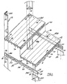
- FIG. 1 which shows the completed package in its partially assembled form. It consists of a floor/ ceiling component collectively designated 10 and consisting, in this embodiment, of two halves 10A and 10B.
- the component 10 can consist of a plurality of parts but should contain at least two parts.
- This component 10 comprises a plurality of spaced and parallel support joists 11 surmounted by a floor or ceiling panel or deck 12 which is secured to the supports by nails, screws or other conventional means and indicated by reference character 13.
- the support joists are in the form of trusses but of course conventional one piece joists can be used.
- the trusses incorporate the upper member 14, a lower member 15, vertical struts 16 and diagonal struts 17 all of which are substantially conventional.
- the two halves 10A and 10B when assembled together in side by side relationship include a support in the form of a truss or joist immediately adjacent the inner edges 18A and 18B which facilitates the joining of the two halves together by means of screws or other fasteners (not illustrated).
- L-shaped members 19 Two types are shown, namely, L-shaped members 19 and straight or planar members 20.
- the L-shaped members 19 are specifically provided for corner supports and the planar members 20 for intermediate supports.
- L-shaped members which may be metal or wood, are of a height to space a pair of units 10 a sufficient distance apart so that one may act as a ceiling (not illustrated) and the other as a floor as illustrated in Figure 1.
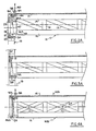
- perimetrical beam members 21 are secured to a base (not illustrated) and extend upwardly and adjacent corner members 19 and intermediate members 20 receive a perimetrical beam member collectively designated 21 as will hereinafter be described.
- perimetrical beam members include an upper horizontal member 22, a lower horizontal member 23, vertical struts 24 and diagonal struts 25 and are similar in construction to the trusses 11. However the end vertical members 24A are substantially wider than the intermediate members 24 for strength purposes.
- Perimetrical beam blocks 26 and 27 are provided at each end of the perimetrical beam members 21 to facilitate assembly to the vertical support members 19 and 20.
- the perimetrical beam block 26 rests on the flange 28 of the corner member which is parallel to the planar member 20 and is of a size that, when installed, the adjacent end of the perimetrical beam member 21 also rests on this flange and can be secured thereto and to the block 26, by means of nails or screws as will hereinafter be described.
- the same method of attachment occurs with beam block 27 and the adjacent end of the perimetrical beam upon the planar vertical support 20.
- marks or indicia are provided on the upper edge of the member 20 as indicated by reference character 29 to facilitate the location of the block 27 thereon and leave equal space upon either side of the receipt of the adjacent end of the perimetrical beam 21.
- An anchoring support strut 30 is secured to the lower horizontal member 23 of the perimetrical beam and the corresponding member 31 of the block 27 and 32 of the block 26. This extends inwardly and permits nails or screws 33 to be engaged diagonally through the member 30 and into the vertical supports 19 or 20 as shown in phantom in Figure 3.
- the block 26 may be secured to the adjacent end of the beam 21 by means of nails or screws as desired.
- a pair of such perimetrical beams are provided as illustrated in Figure 1 to receive the unit 10.
- Each half of the unit 10 includes a beam member engaging strut 34 secured to the ends of the joists or trusses 11 perpendicular thereto and between the upper and lower members 14 and 15, it being understood that there is such a strut 34 on each end of both sections 10A and 10B.
- a unit engaging strut 35 is secured to the inner face of each of the perimetrical beam members 25 and intermediate the upper and lower members 22 and 23 thereof and parallel therewith so that when the unit 10 is lowered into place, the struts 34 engage upon the struts 35 as clearly in Figures 2 and 3 and these struts are positioned so that the upper surface of the deck 12 is substantially flush with the upper members 22.
- the outer end truss members 11 of the unit 10 complete the perimetrical beam support provided by the perimetrical beams 21 and securement may be effected adjacent the outer corners through diagonal apertures 36 and into the upper members 26 and 14 of the beam blocks and end trusses respectively.
- any wiring or plumbing can be accessed through these apertures and also through additional apertures 38 adjacent the support ends of the halves 10A and 10B.
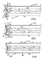
- FIGS. 2 and 3 show the method of assembly and disassembly by the use of lifting hooks 39 attachable to ropes or cables 40 which in turn may be connected to a crane or winch (not illustrated).
- hook elements 39 are angulated as at 39A and engage downwardly through the apertures 38 adjacent the truss ends of the sections 10A and 10B.
- the hooked ends then engage within apertures 41 formed in the perimetrical beam engaging strips 34 and permit easy lifting of the individual sections.
- the angulated or sloped ends 42 of the joists or trusses act to guide the sections into position so that the strips 34 engage upon strips 35 whereupon securement may be undertaken via nails 33 as hereinbefore described and shown in Figure 3.
- the floor/ceiling unit 10 is formed in two or more portions and as an example, the two portions illustrated may each be 4800 mm by 3000 mm so that when they are secured together and installed as shown in Figures 1, 2 and 3, the overall size of the floor/ceiling unit 10 becomes 4800 mm by 6000 mm.
- Either a dividing wall may be mounted upon the planar vertical supports 20 or, further floor/ceiling panels 10 may be placed to the side of the existing panel or unit terminating of course in two L-shaped members 19 to complete the room unit. Also end walls, doors and windows may be installed in walls attached to the vertical support members all of which is clearly disclosed in my previous Patent No. CA-A-1,018,719.
- the packaging for transportation or storage of the entire assembly with the divided floor/ceiling unit permitting a package to be provided which is within the limits for road transport.
- the overall width of the package would be approximately 3000 mm (9 3/4 feet) with a length of 4800 mm (approximately 15 3/4 feet).
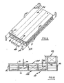
- FIGs 4, 5 and 6 show details of the packaging concept.
- Each half or portion of the unit 10 can be nested one within the other by reversing one of the portions through 180° in a vertical plane relative to the other portion so that the joists of this rotated portion face uppermost thus enabling the joists of the first portion to be lowered into nesting engagement with the lower portion as clearly shown in Figures 4, 5 and 6 with the beam engaging strips 34 resting upon one another as clearly shown in Figure 4 and the joists or trusses being in side by side relationship as clearly shown in Figure 6.
- Screws or other fastening means 43 may be engaged through the vertical or diagonal members of the joists thus holding the sections together and the remaining structure such as the vertical supports 19 and 20 may be stored within the cavities defined by the joists and the upper and lower decks or panels 12.
- the lifting hooks 39 can still be engaged through apertures 9 and into the apertures 39A so that the entire package can be lifted from one location to another and to further secure the two portions together, blocks or strips 44 may span the ends of the joists and may be secured thereto by nails or screws as clearly shown in Figure 5.
- the beam member engaging strut 34 and unit engaging strut 35 are eliminated.
- the end of the lower member 15 is secured to the lower end member 16A of the support or truss 11 and extends downwardly therefrom, the downwardly extending portion also being inclined downwardly and inwardly indicated by reference character 48.
- a board or the like 49 is secured by nails or screws, to the end of the upper member 14 and extends part way down the sloping portion 47 of the member 16A. This board engages the underside of the panel 12. Blocks or strips 49 are secured to the underside of the panel 12 upon each side of the hook aperture 38 which inboard slightly from the aperture shown in Figures 2 and 3 and the board 49 may be nailed or otherwise secured to one of these blocks as illustrated in Figure 2A, by reference character 50.
- the hook 39 engages through the aperture 38 and under one of the blocks or strips 49 as illustrated in Figures 2A and 4A and the sloping relationship of the board 49, the slope 47 and the portion 48 all assist in guiding the unit into position between the opposing perimetrical beams 21.
- the narrow horizontal edge 51 of the member 16A engages upon the support struts 30 and nails or other fasteners 52 secure the panel 12 to the upper member 22 of the beams 21 and the struts 30 to the members 16A as clearly shown in Figure 3A.
- the aforementioned hook 39 may be used to lower the upper half 10A into position with the lower half 10B with the sloping surfaces of the board 49 once again assisting in the positioning of the portions one within the other whereupon end members 44A may be placed between the ends of the panels 12 and fasteners such as screws or nails 53 may secure the halves to the beam members 44A thus securing the halves together as a package, assisted by similar fasteners 54 engaging through the intersections of the diagonal struts 17 of the adjacent situated end trusses so that the hook 39 may be used to lift the entire package once the halves are secured together.
- the board 49 is relatively thin and assists in securing the rigidity of the floor component during pickup.
- the angular ends or inclination of the supported joists ensures a smooth positioning of the component and, once in position, substantially zero clearance exists between the upper side of the perimetrical beam and the outer surface of the board 49 and between the sloping surface 48 of the lower side of the truss and the upper inner corner of the member 30 of the perimetrical beam.
- the preferred embodiment assures transfer of loads from the joists directly to the wall with no opening or with lintels (not illustrated) above openings (applicable in hotels or the like between separating walls), which assures smooth positioning of the floor components with zero tolerance achieved after the floor components are properly positioned and, once this zero tolerance is achieved, the positions of bearing wall, perimetrical beams, and floor/ roof components are automatically adjusted.
- angles or inclinations of the ends of the joists, the thickness of the plates or boards 49, and the heights of the perimetrical beams apply to both the assembled structure and to the "package" configuration.
- the overall width of the completed package is designed to be less than the maximum allowable width permissible upon highways and that a relatively large number of packages may be stacked one upon the other for transportation by truck or train.
- Step 1 Once the package is opened, the beams stored in the bottom core are placed on support walls or columns depending upon design parameters. If the latter, these can also be stored in the package and are erected first.
- Each of the beams 21 is an integral part of the floor/roof component as a whole, bearing securely at one end, either both of the halves 10A and 10B of the unit 10 or all of the portions if more than two are involved. If the span between the support walls 20 and columns or L-shaped vertical members 19 is shorter than the length of the bearing members or beams 21 of the floor/roof components, the beam may be stored in the hollow core of the package in one piece.
- the module While no span should be longer than the distance between the vertical supports, the module may be substantially longer and the difference between the two may be projected in the lengths of the support walls with the continuity of the perimetrical beam being ensured by additional beam blocks similar to those indicated by reference characters 26 and 27. These can also be stored in the hollow space in the package.
- Step 2 After the two halves or plurality of portions of the floor/roof component are positioned in the structure as illustrated in Figures 2 and 3, the perimetrical beam members 21 not only carry the full load but also close that portion of either floor or roof structure. All connecting points such as screws from the upper deck of the floor/roof component to the top of the perimetrical beam member or screws from the bottom beam block to to the top of the either straight or L-shaped vertical wall members are only accessible from the inside space limited in vertical direction by the size of the floor/roof component.
- the openings 36 in the deck at the corners of the end portion of the floor/roof component receive the brace for a corner wall for another storey to insure that the prefabricated L-shaped vertical member or wall is positioned in all three directions automatically with no measuring or adjusting being necessary.
- the shape of the opening 36 is identical to the shape of the brace 37 at the bottom of the next vertical member and the thickness of the deck of the floor/roof components is the same as the thickness of the brace which can if desired, be the portion of the deck that is removed to form aperture 36.
- This interlocking system also strengthens the structure as a whole while the corner wall lower side of the upper floor can be secured to the top deck of the floor/roof component below by screws or the like once again applied from the inside of the floor or roof component below the top deck.
- Step 3 While the vertical walls 20 and columns 19 which support the floor/roof component, may bear load from either one or two structural modules, the perimetrical beam member 21 of one floor/roof component is not statically connected with the beam of the other.
- the full size floor or roof components can thus be assembled on the ground and the entire floor or roof may be lifted and positioned on the supports as one unit.
- the present system provides an easy method of construction of floors or roofs because a larger and stronger structure may be built from lighter, but very rigid, pre- fabricated components which are easy to transport and erect.
- electrical wiring and plumbing may be pre-built in the structural components to a greater degree than is possible in conventional pre-fabricated structures with traditional built floors or roofs.
Claims (11)
Priority Applications (1)
| Application Number | Priority Date | Filing Date | Title |
|---|---|---|---|
| AT85308765T ATE57218T1 (de) | 1984-12-18 | 1985-12-02 | System von strukturelementen, die ihre eigene verpackung zur lagerung und zum transport bilden und deren zusammenbau. |
Applications Claiming Priority (2)
| Application Number | Priority Date | Filing Date | Title |
|---|---|---|---|
| CA470455 | 1984-12-18 | ||
| CA000470455A CA1192368A (fr) | 1984-12-18 | 1984-12-18 | Systeme de groupage d'elements prefabriques pour le batiment aux fins de leur transport et de leur stockage |
Publications (3)
| Publication Number | Publication Date |
|---|---|
| EP0185484A2 EP0185484A2 (fr) | 1986-06-25 |
| EP0185484A3 EP0185484A3 (en) | 1987-05-06 |
| EP0185484B1 true EP0185484B1 (fr) | 1990-10-03 |
Family
ID=4129402
Family Applications (1)
| Application Number | Title | Priority Date | Filing Date |
|---|---|---|---|
| EP19850308765 Expired - Lifetime EP0185484B1 (fr) | 1984-12-18 | 1985-12-02 | Système d'éléments de structure formant leur propre emballage pour l'entreposage et le transport et assemblage de ces éléments |
Country Status (9)
| Country | Link |
|---|---|
| US (1) | US4640412A (fr) |
| EP (1) | EP0185484B1 (fr) |
| JP (1) | JPS61146946A (fr) |
| KR (1) | KR900006934B1 (fr) |
| CN (1) | CN1006564B (fr) |
| AT (1) | ATE57218T1 (fr) |
| AU (1) | AU559268B2 (fr) |
| CA (1) | CA1192368A (fr) |
| DE (1) | DE3580009D1 (fr) |
Families Citing this family (13)
| Publication number | Priority date | Publication date | Assignee | Title |
|---|---|---|---|---|
| US5447000A (en) * | 1988-09-26 | 1995-09-05 | Larsen; Peter W. | Prefabricated building kit |
| GB8822562D0 (en) * | 1988-09-26 | 1988-11-02 | Larsen P W | Prefabricated building |
| US5279436A (en) * | 1992-07-16 | 1994-01-18 | Tecco, Ltd. | Knock down shipping container using building components |
| US5333426A (en) * | 1993-01-06 | 1994-08-02 | Forintek Canada Corporation | Wood frame construction system with prefabricated components |
| US6296133B1 (en) | 2000-06-02 | 2001-10-02 | Joseph L. Cobane | Container for vinyl siding |
| US20070283632A1 (en) * | 2005-04-15 | 2007-12-13 | Mcinerney Kevin | Ring Beam Structure And Method Of Constructing A Timber Frame |
| US20080260507A1 (en) * | 2005-06-28 | 2008-10-23 | Hernandez Mark S | Modular and collapsible storage and/or transport container apparatus and method and utility trailer system incorporating the same |
| US20120013093A1 (en) * | 2007-04-17 | 2012-01-19 | A Noy Development Ii, Llc | Modular and collapsible storage and/or transport container apparatus and method and utility trailer system |
| JP5504579B2 (ja) * | 2008-05-12 | 2014-05-28 | 積水ハウス株式会社 | 住宅の床着脱構造及び住宅の改装方法 |
| JP6283228B2 (ja) * | 2014-02-03 | 2018-02-21 | 鹿島建設株式会社 | 建築構法 |
| US9145285B1 (en) * | 2015-01-08 | 2015-09-29 | Finfrock Industries, Inc. | Panel lifting apparatus and process |
| CN107587739A (zh) * | 2016-07-06 | 2018-01-16 | 沈阳科华工业设备制造有限公司 | 一种用于组装立体车库的组装件 |
| CN108222277B (zh) * | 2018-02-27 | 2023-10-20 | 中材科技股份有限公司 | 可模块化空间扩展的快装活动房结构及快装活动房的安装方法 |
Family Cites Families (14)
| Publication number | Priority date | Publication date | Assignee | Title |
|---|---|---|---|---|
| US2570234A (en) * | 1946-04-16 | 1951-10-09 | Philip W Harris | Portable floor construction |
| US2950078A (en) * | 1959-09-14 | 1960-08-23 | Lilly Co Eli | Skid-pallet combination |
| US2998132A (en) * | 1960-11-21 | 1961-08-29 | Acme Steel Co | Package |
| US3284966A (en) * | 1963-12-05 | 1966-11-15 | Terrapin Overseas Ltd | Collapsible buildings |
| GB1114091A (en) * | 1965-06-09 | 1968-05-15 | Terrapin Internat Ltd | Improvements in or relating to prefabricated floor structures and to building structures made therewith |
| US3683571A (en) * | 1969-11-03 | 1972-08-15 | Armadillo Mfg Co | Built-in lift assembly for building |
| US3752087A (en) * | 1971-11-09 | 1973-08-14 | Allis Chalmers | Pallet construction for increased density of loading |
| US3756167A (en) * | 1972-07-24 | 1973-09-04 | Banner Metals Inc | Wire-formed pallet |
| US3895588A (en) * | 1974-03-04 | 1975-07-22 | Banner Metals Division Interco | Heavy duty shipping tray |
| US4005556A (en) * | 1974-09-26 | 1977-02-01 | The United States Of America As Represented By The Secretary Of Agriculture | Lightweight truss-framed house |
| CA1018719A (en) * | 1975-11-27 | 1977-10-11 | Joseph Skvaril | Prefabricated cube construction system for housing and civic development |
| FR2413279A1 (fr) * | 1977-12-27 | 1979-07-27 | Tecma Sa | Palettes double face a elements separables |
| JPS54105812A (en) * | 1978-02-07 | 1979-08-20 | Toyo Engineering Corp | Portable floor base |
| JPS54113458A (en) * | 1978-02-21 | 1979-09-05 | Yoshinari Masuyama | Production of high nutritious food based on beans |
-
1984
- 1984-12-18 CA CA000470455A patent/CA1192368A/fr not_active Expired
- 1984-12-27 US US06/686,829 patent/US4640412A/en not_active Expired - Lifetime
- 1984-12-28 AU AU37219/84A patent/AU559268B2/en not_active Ceased
-
1985
- 1985-12-02 DE DE8585308765T patent/DE3580009D1/de not_active Expired - Lifetime
- 1985-12-02 EP EP19850308765 patent/EP0185484B1/fr not_active Expired - Lifetime
- 1985-12-02 AT AT85308765T patent/ATE57218T1/de not_active IP Right Cessation
- 1985-12-03 KR KR1019850009052A patent/KR900006934B1/ko not_active IP Right Cessation
- 1985-12-17 JP JP60284180A patent/JPS61146946A/ja active Pending
- 1985-12-17 CN CN85108830A patent/CN1006564B/zh not_active Expired
Also Published As
| Publication number | Publication date |
|---|---|
| DE3580009D1 (de) | 1990-11-08 |
| AU559268B2 (en) | 1987-03-05 |
| KR860005100A (ko) | 1986-07-18 |
| EP0185484A3 (en) | 1987-05-06 |
| AU3721984A (en) | 1986-07-03 |
| CN85108830A (zh) | 1986-07-16 |
| KR900006934B1 (ko) | 1990-09-25 |
| ATE57218T1 (de) | 1990-10-15 |
| US4640412A (en) | 1987-02-03 |
| CA1192368A (fr) | 1985-08-27 |
| CN1006564B (zh) | 1990-01-24 |
| EP0185484A2 (fr) | 1986-06-25 |
| JPS61146946A (ja) | 1986-07-04 |
Similar Documents
| Publication | Publication Date | Title |
|---|---|---|
| US5950374A (en) | Prefabricated building systems | |
| US5950373A (en) | Transportable structure kit | |
| US5333426A (en) | Wood frame construction system with prefabricated components | |
| US6463705B1 (en) | Container for prefabricated transportable buildings | |
| EP0185484B1 (fr) | Système d'éléments de structure formant leur propre emballage pour l'entreposage et le transport et assemblage de ces éléments | |
| US20080000177A1 (en) | Composite floor and composite steel stud wall construction systems | |
| WO2006122372A1 (fr) | Bati de construction modulaire | |
| US4854104A (en) | Roof truss assembly | |
| US3707814A (en) | Pre-fabricated stairway | |
| US7325362B1 (en) | Steel roof truss system | |
| US3738069A (en) | Modular building construction | |
| US20220213684A1 (en) | Modular composite action panel and structural systems using same | |
| US4294052A (en) | Prefabricated load bearing structure | |
| US4807410A (en) | Self-containing package system for storage and transportation of pre-fabricated portions of a building structure and the assembly thereof | |
| US4242845A (en) | Connecting hinge system for prefabricated building foldable panel structures | |
| CA2592820A1 (fr) | Systemes de construction de planchers composites et de murs composites a tiges d'acier | |
| US3748794A (en) | Building construction and method | |
| JP2001115559A (ja) | コンテナハウス用コンテナ及びコンテナハウス | |
| US4679374A (en) | Building construction method | |
| JP2565628B2 (ja) | マンサード屋根構造とその施工方法 | |
| KR830000047B1 (ko) | 건축용 조립식 빌딩 유닛 | |
| EP0086201B1 (fr) | Portique | |
| AU719296B2 (en) | A transportable structure kit | |
| JPH07217230A (ja) | 吊り階段及びその仮設方法 | |
| EP0015766A1 (fr) | Structures de toiture |
Legal Events
| Date | Code | Title | Description |
|---|---|---|---|
| PUAI | Public reference made under article 153(3) epc to a published international application that has entered the european phase |
Free format text: ORIGINAL CODE: 0009012 |
|
| AK | Designated contracting states |
Kind code of ref document: A2 Designated state(s): AT BE CH DE FR GB IT LI LU NL SE |
|
| PUAL | Search report despatched |
Free format text: ORIGINAL CODE: 0009013 |
|
| AK | Designated contracting states |
Kind code of ref document: A3 Designated state(s): AT BE CH DE FR GB IT LI LU NL SE |
|
| 17P | Request for examination filed |
Effective date: 19870828 |
|
| 17Q | First examination report despatched |
Effective date: 19880229 |
|
| DIN1 | Information on inventor provided before grant (deleted) | ||
| RAP1 | Party data changed (applicant data changed or rights of an application transferred) |
Owner name: SKVARIL, JOSEPH |
|
| GRAA | (expected) grant |
Free format text: ORIGINAL CODE: 0009210 |
|
| AK | Designated contracting states |
Kind code of ref document: B1 Designated state(s): AT BE CH DE FR GB IT LI LU NL SE |
|
| REF | Corresponds to: |
Ref document number: 57218 Country of ref document: AT Date of ref document: 19901015 Kind code of ref document: T |
|
| REF | Corresponds to: |
Ref document number: 3580009 Country of ref document: DE Date of ref document: 19901108 |
|
| RAP4 | Party data changed (patent owner data changed or rights of a patent transferred) |
Owner name: SKVARIL, JOSEPH |
|
| ITTA | It: last paid annual fee | ||
| PG25 | Lapsed in a contracting state [announced via postgrant information from national office to epo] |
Ref country code: LU Free format text: LAPSE BECAUSE OF NON-PAYMENT OF DUE FEES Effective date: 19901231 |
|
| ITF | It: translation for a ep patent filed |
Owner name: DR. ING. A. RACHELI & C. |
|
| ET | Fr: translation filed | ||
| PLBE | No opposition filed within time limit |
Free format text: ORIGINAL CODE: 0009261 |
|
| STAA | Information on the status of an ep patent application or granted ep patent |
Free format text: STATUS: NO OPPOSITION FILED WITHIN TIME LIMIT |
|
| 26N | No opposition filed | ||
| PGFP | Annual fee paid to national office [announced via postgrant information from national office to epo] |
Ref country code: SE Payment date: 19931115 Year of fee payment: 9 |
|
| PGFP | Annual fee paid to national office [announced via postgrant information from national office to epo] |
Ref country code: DE Payment date: 19931207 Year of fee payment: 9 |
|
| PGFP | Annual fee paid to national office [announced via postgrant information from national office to epo] |
Ref country code: BE Payment date: 19931213 Year of fee payment: 9 |
|
| PGFP | Annual fee paid to national office [announced via postgrant information from national office to epo] |
Ref country code: FR Payment date: 19931228 Year of fee payment: 9 |
|
| PGFP | Annual fee paid to national office [announced via postgrant information from national office to epo] |
Ref country code: CH Payment date: 19931229 Year of fee payment: 9 |
|
| PGFP | Annual fee paid to national office [announced via postgrant information from national office to epo] |
Ref country code: AT Payment date: 19931230 Year of fee payment: 9 |
|
| PGFP | Annual fee paid to national office [announced via postgrant information from national office to epo] |
Ref country code: NL Payment date: 19931231 Year of fee payment: 9 |
|
| PG25 | Lapsed in a contracting state [announced via postgrant information from national office to epo] |
Ref country code: AT Effective date: 19941202 |
|
| PG25 | Lapsed in a contracting state [announced via postgrant information from national office to epo] |
Ref country code: SE Effective date: 19941203 |
|
| PG25 | Lapsed in a contracting state [announced via postgrant information from national office to epo] |
Ref country code: LI Effective date: 19941231 Ref country code: CH Effective date: 19941231 Ref country code: BE Effective date: 19941231 |
|
| EAL | Se: european patent in force in sweden |
Ref document number: 85308765.8 |
|
| BERE | Be: lapsed |
Owner name: SKVARIL JOSEPH Effective date: 19941231 |
|
| PG25 | Lapsed in a contracting state [announced via postgrant information from national office to epo] |
Ref country code: NL Effective date: 19950701 |
|
| PG25 | Lapsed in a contracting state [announced via postgrant information from national office to epo] |
Ref country code: FR Effective date: 19950831 |
|
| REG | Reference to a national code |
Ref country code: CH Ref legal event code: PL |
|
| NLV4 | Nl: lapsed or anulled due to non-payment of the annual fee |
Effective date: 19950701 |
|
| PG25 | Lapsed in a contracting state [announced via postgrant information from national office to epo] |
Ref country code: DE Effective date: 19950901 |
|
| EUG | Se: european patent has lapsed |
Ref document number: 85308765.8 |
|
| REG | Reference to a national code |
Ref country code: FR Ref legal event code: ST |
|
| PGFP | Annual fee paid to national office [announced via postgrant information from national office to epo] |
Ref country code: GB Payment date: 19961128 Year of fee payment: 12 |
|
| PG25 | Lapsed in a contracting state [announced via postgrant information from national office to epo] |
Ref country code: GB Free format text: LAPSE BECAUSE OF NON-PAYMENT OF DUE FEES Effective date: 19971202 |
|
| GBPC | Gb: european patent ceased through non-payment of renewal fee |
Effective date: 19971202 |