EP0184721A2 - Système pour mesurer la pression - Google Patents
Système pour mesurer la pression Download PDFInfo
- Publication number
- EP0184721A2 EP0184721A2 EP85115062A EP85115062A EP0184721A2 EP 0184721 A2 EP0184721 A2 EP 0184721A2 EP 85115062 A EP85115062 A EP 85115062A EP 85115062 A EP85115062 A EP 85115062A EP 0184721 A2 EP0184721 A2 EP 0184721A2
- Authority
- EP
- European Patent Office
- Prior art keywords
- optical fiber
- light
- pressure
- fiber means
- measuring system
- Prior art date
- Legal status (The legal status is an assumption and is not a legal conclusion. Google has not performed a legal analysis and makes no representation as to the accuracy of the status listed.)
- Granted
Links
Images

Classifications
-
- G—PHYSICS
- G01—MEASURING; TESTING
- G01L—MEASURING FORCE, STRESS, TORQUE, WORK, MECHANICAL POWER, MECHANICAL EFFICIENCY, OR FLUID PRESSURE
- G01L9/00—Measuring steady of quasi-steady pressure of fluid or fluent solid material by electric or magnetic pressure-sensitive elements; Transmitting or indicating the displacement of mechanical pressure-sensitive elements, used to measure the steady or quasi-steady pressure of a fluid or fluent solid material, by electric or magnetic means
- G01L9/0041—Transmitting or indicating the displacement of flexible diaphragms
- G01L9/0076—Transmitting or indicating the displacement of flexible diaphragms using photoelectric means
- G01L9/0077—Transmitting or indicating the displacement of flexible diaphragms using photoelectric means for measuring reflected light
Definitions
- This invention relates to a pressure measuring system.
- One known pressure measuring system which is relatively little affected by the influences of the electromagnetic induction, for example, utilizes optical fibers.
- light from a light source is projected onto a pressure-receiving diaphragm mirror via an optical fiber.
- the reflected light from the mirror is then projected to photosensitive elements through an optical fiber provided for light reception.
- Received reflected light is then converted to an electrical signal, and pressure is measured based on the change in the reflected light due to deflection in the diaphragm mirror.
- the amount of reflected light received by the optical fiber for light reception is small, and in fact the reflected amount of light is considerably reduced.
- the reduction in the received light amount sets a limitation on the sensitivity of the measurement obtained.
- an objects of this invention are to provide a novel pressure measuring system which has a sturdy resistance against, and is unaffected by, electromagnetic induction arising due to large currents and high voltages being in close proximity, and which enables one to obtain a more accurate and sensitive pressure, measurements
- Another object of the invention is to provide a pressure measuring system which can strongly resist the effects of electromagnetic induction or the like which accompanies large current and high voltage.
- a first embodiment of the pressure measuring system in accordance with the present invention which includes a light source, an optical fiber associated with the light source for transmitting a light beam from the light source, a pressure-receiving diaphragm which is equipped with a reflecting surface for reflecting the light beam transmitted by the optical fiber, wherein the reflecting surface undergoes deflection in relation to the pressure to be measured, an optical fiber for light reception which receives the reflected light from the pressure-receiving diaphragm, a reference optical fiber which is arranged substantially coextensively with approximately parallel to the light source optical fiber and the light reception optical fiber, and which transmits a light beam from the light source back and forth along the same path as the light source optical fiber and the optical fiber for light reception, a first photosensitive element which converts the reflected light transmitted by the optical fiber for light reception to an electrical signal, a second photosensitive element which converts the light transmitted by the reference optical fiber to an electrical signal, and an operational circuit which removes the variations due to external
- a novel pressure measuring system including a light source, an optical fiber associated with the light source for transmitting a light beam from the light source, a pressure-receiving diaphragm which is equipped with a reflecting surface for reflecting light carried by the light source optical fiber, wherein the diaphragm undergoes a deflection in relation to the pressure to be measured, an optical fiber for light reception which receives and transmits the reflected light from the presure-receiving diaphragm, a photosensitive element which converts the reflected light transmitted by the optical fiber for light reception, and an output adjusting circuit which establishes a linear relationship between the output signal from the photosensitive element and the received pressure, wherein there is set an angle with respect to the normal to the reflecting surface for the light source optical fiber and the optical fiber for light reception in order to make it possible to reflect light from one of said optical fibers to the other irrespective of any deformation of the diaphragm.
- the pressure measuring system of the invention includes a detection section which is attached air-tight to the object 12 to be measured via a sealing material 14, a pressure measuring section 20 which is installed a distance apart from the detection section 10, and which is equipped with a light source, photosensitive elements and processing circuits for outputting the measured value of the pressure, and an optical fiber section which is provided between the detection section 10 and the measuring section 20.
- a pressure-receiving diaphragm 1 which receives pressure P
- a light source 3 an optical fiber 5 for light source 3 which transmits the light from the light source 3 to the reflecting surface la of the pressure-receiving diaphragm
- an optical fiber 7 which transmits the reflected light from the reflecting surface la
- a first photosensitive element 9a which converts the reflected light into an electrical signal.
- a reference optical fiber 13 which transmits reference light from the light source 3 back and forth between the light source 3 and the sensor head 11, and a second photosensitive element 9b which converts the reference light into an electrical signal.
- an operational circuit 15 which carries out a divisional operation in which the reflected signal output from the first photosensitive element 9a is divided by the reference signal output adjusting circuit 17 which establishes a linear relationship between the output signal from the operational circuit means 15 and the received pressure.
- the pressure-receiving diaphragm 1 is attached to the installation part 19 and is designed to undergo a deflection in proportion to the pressure P to be measured upon application of such pressure and based thereon change the direction of the reflected light from the reflecting surface la.
- the reflecting surface la may have been processed, for example, by buffer polishing.
- the light source 3 can be an ordinary light source such as an LED.
- the optical fiber 5 and the optical fiber 7 are installed with a predetermined angle of tilt with respect to the normal to the reflecting surface la, and are arranged so as to turn light from one direction into another direction within the sensor head 11.
- the angular orientation of the fibers 5 and 7 may be constructed such that the above tilt is given only to one or the other or both of the optical fibers 5 and 7.
- the installation section 19 for the pressure-receiving diaphragm 1 and the sensor head 11 are joined via a sealing section 21, at a position with a predetermined separation between the pressure-receiving diaphragm 1 and the edge surfaces of the optical fiber 5 and the optical fiber 7 in the sensor head 11.
- This sealing is formed, for instance, by electron beam welding to seal off the space 23 bounded by the reflecting surface la and the sensor head 11.
- the space 23 is connected to a pipe 25 for vacuum pumping. Pipe 25 is blocked up after vacuum pumping is completed to form a pressure measuring system of the absolute pressure type.
- a valve not shown, is installed on the pipe 25.
- the pipe 25 for vacuum pumping is connected through a vacuum apparatus via this valve.
- the pipe 25 for vacuum pumping 25 is plugged by squeezing it between the valve and the sensor head 11. While maintaining the plugging, the pipe 25 is cut-off at a position nearer to the valve than the plugged position and welded at the cut-off section.
- the reference optical fiber 13 is arranged parallel to the optical fiber 5 and the optical fiber 7 and is substantially coextensive therewith. More particularly, the reference optical fiber 13 is extended along the optical fiber 5, and reaches the sensor head 11. The reference optical fiber 13 reaches to the inside of the sensor head 11 and is folded back and extended along the optical fiber 7 to reach the second photosensitive element 9b.
- the first and second photosensitive elements 9a and 9b are constructed in a similar manner and each converts light into a corresponding electrical signal.
- elements 9a and 9b convert the light received from the optical fiber 7 and the reference optical fiber 13 to electrical signals respectively corresponding to ,the amount of light received and apply these electrical signals to the operational circuit 15.
- the light rays from the light source 3 are, irradiated on the reflecting surface la by means of the optical fiber 5.
- the reflected light from the reflecting surface la is led by the optical fiber 7 to the first photosensitive element 9a where it is converted to a corresponding electrical snginal output.
- the pressure-receiving diaphragm 1 is deflected in proportion to the pressure P received, which varies the amount of reflected light to be incident from the reflecting surface la on the optical fiber 7.
- the reflected signal output and the reference signal output produced by the first photosensitive element 9a and the second photosensitive element 9b, respectively, are input to the operational circuit 15 where division of the reflected signal output by the referenc signal output is carried out, and the result is output.
- the output from the operational circuit 15 is input to an output adjusting circuit 17 where a linear relationship between the output signal from the operational means 15 is established.
- the amount of the reflected light received by the optical fiber 7 for light reception from the reflecting surface la of the pressure-receiving diaphragm 1 which is in proportion to the pressure P it receives may be represented, for instance, by I.
- I is the rate of change in the amount of received reflected light which is proportional to the pressure P.
- the disturbance coefficient when vibrations exist in the optical fibers 5, 7, and 13 due to external force, and so forth, that is, when external disturbances exist is called , the amount of reflected light from the reflecting surface la which is distorted in proportion to the pressure P will become I.
- the amount of reference light which passes through the reference optical fiber 13 in this case will be I.
- the first photosensitive elment 9a receives an amount, I, of light from the optical fiber 7, and converts it into an electrical signal, for instance, E (where E I) which is input to the operational circuit 15.
- the second photosensitive element 9b receives an amount, I, of light from the reference optical fiber 13, and converts it similarly to an electrical signal E which is input to the operational circuit 15.
- the optical fiber 5 and the optical fiber 7 in the sensor head 11 are constructed to have a predetermined angle with respect to the normal to the reflecting surface la, the amount of reflected light received by the optical fiber 7 is increased in comparison to the prior art pressure measuring system which has an angle of 0 0 with respect to the normal to the reflecting surface la. Consequently, even when a reduction in the amount of reflected light occurs due to stains on the reflecting surface la, or the like, the rate of the reduced amount in relation to the total amount of light is low, so that the present system is less susceptible to influences due to reduction in the light amount, and hence it is possible to carry out a more accurate pressure measurement.
- the space 23 formed between the reflecting surface la and the sensor head 11 is kept in a vacuum state. Therefore, there will be few stains on the reflecting surface la. This prevents a reduction in the amount of reflected light due to stains, enabling one to have more accurate pressure measurements.
- the measuring system will function as a pressure measuring system of the absolute pressure type since the space 23 is kept under vacuum.
- Figure 2 shows a second embodiment of the present invention, which unlike the case of the first embodiment is constructed such that the reference optical fiber 13 is disconnected in the sensor head 11, and the reflected light from a wallsurface 27 formed in the sensor head 11 is led to the second photosensitive element 9b.
- the wall surface 27 is given such a mirror surface processing as aluminum evaporation. Therefore, in addition to obtaining the improved pressure measurement as in the first embodiment provides easy assembling of the system.
- the remaining construction is substantially identical to that of the first embodiment, so that further explanation is omitted.
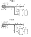
- Figure 3 relates to a third embodiment of the present invention which shows a further simplification of the invention.
- the reference optical fiber 13 is constructed by a single line, and light reflected from the wall 27 in the sensor head 11 is arranged to be branched off by a coupler 29 which is provided at the midpoint in the optical fiber for reference 13, to be led to the second photosensitive element 9b. Therefore, in addition to the fact that the improved pressure measurement of the first embodiment is obtainable, the third embodiment further is easy to construct and makes possible compacting of the system.
- the manufacture of the system due to this embodiment may further be simplified since the coupler 29 may be constructed as a half mirror, or instead of giving a mirror surface finishing to the wall surface 27, the end surface 13a of the reference optical fiber 13 in the sensor head 11 may be given a mirror surface finishing by means of aluminum evaporation or the like.
- the remaining construction is substantially identical to the first embodiment and further explanation is therefore omitted.
- Figure 4 shows a fourth embodiment of the present invention which is a further simplification of the third embodiment.
- two couplers 31 and 33 are placed in the optical fiber 5.
- Light is branched to the optical fiber 7 from the coupler, 31, while branching to the first photosensitive element 9a is made through the other coupler 33. Therefore, in addition to the fact that effects similar to the third embodiment are obtained, a further compacting of the construction of the system is achieved by the fourth embodiment.
- the remaining construction is substantially identical to the third embodiment and further explanation is therefore omitted.
- the present invention is not limited to the embodiments described in the foregoing.
- the light source may be replaced by a laser light source.
- the optical fiber 5, the optical fiber 7, and reference optical fiber 13 may be constructed of fiber bundles.
- the operational circuit 15 use may be made of a multiplicative operational circuit, an additional operational circuit, or a subtractional operational circuit.
- stains on the reflecting surface may be prevented by sealing an inert gas in the space 23.
- the.pressure measuring system will function as a differential pressure-type system.
- the present invention may be embodied in various modified forms.
- optical fibers are used for signal transmission so that the system of the invention is insensitive to electromagnetic inductive noise accompanying a large current and a high voltage, which enables accurate pressure measurements.
- the reflected signal output which is obtained by converting the reflected light from the reflecting surface of the pressure-receiving diaphragm into an electrical signal
- the reference signal output derived from reference light which travelled along substantially the same path between the light source and the photosensitive element
- the optical fiber 5 and the optical fiber 7 are given an angle with respect to the normal to the reflecting surface in order to direct light at least from one fiber to the other.
- the amount of reflected light received by the optical fiber 7 will be increased, and it is made less susceptible to the influence of the reduction in the amount of the reflected light due to stains on the reflecting surface or the like, enabling one to obtain more accurate measurements.
- more sensitive measurements of pressure become possible due to increase in the amount of the reflected light.
Landscapes
- Physics & Mathematics (AREA)
- General Physics & Mathematics (AREA)
- Measuring Fluid Pressure (AREA)
Applications Claiming Priority (4)
| Application Number | Priority Date | Filing Date | Title |
|---|---|---|---|
| JP26172384A JPS61139735A (ja) | 1984-12-13 | 1984-12-13 | 光フアイバ圧力計 |
| JP261723/84 | 1984-12-13 | ||
| JP11679485A JPS61275632A (ja) | 1985-05-31 | 1985-05-31 | 圧力測定装置 |
| JP116794/85 | 1985-05-31 |
Publications (3)
| Publication Number | Publication Date |
|---|---|
| EP0184721A2 true EP0184721A2 (fr) | 1986-06-18 |
| EP0184721A3 EP0184721A3 (en) | 1989-04-19 |
| EP0184721B1 EP0184721B1 (fr) | 1992-06-17 |
Family
ID=26455041
Family Applications (1)
| Application Number | Title | Priority Date | Filing Date |
|---|---|---|---|
| EP85115062A Expired - Lifetime EP0184721B1 (fr) | 1984-12-13 | 1985-11-27 | Système pour mesurer la pression |
Country Status (3)
| Country | Link |
|---|---|
| US (1) | US4687927A (fr) |
| EP (1) | EP0184721B1 (fr) |
| DE (1) | DE3586238T2 (fr) |
Cited By (4)
| Publication number | Priority date | Publication date | Assignee | Title |
|---|---|---|---|---|
| EP0455241A2 (fr) * | 1990-05-02 | 1991-11-06 | Dynisco, Inc. | Transducteur de pression optique |
| US5319978A (en) * | 1990-05-02 | 1994-06-14 | Dynisco, Inc. | Optical pressure transducer |
| US5351547A (en) * | 1990-05-02 | 1994-10-04 | Dynisco, Inc. | Optical pressure transducer having a fixed reflector and a movable reflector attached to a diaphragm |
| DE19747343A1 (de) * | 1997-10-27 | 1999-05-06 | Jenoptik Jena Gmbh | Partialdrucksensor |
Families Citing this family (20)
| Publication number | Priority date | Publication date | Assignee | Title |
|---|---|---|---|---|
| US5068527A (en) * | 1987-01-07 | 1991-11-26 | Kabushiki Kaisha Toshiba | Wide range fiber optical displacement sensor |
| US5359445A (en) * | 1987-10-30 | 1994-10-25 | Alliedsignal Inc. | Fiber optic sensor |
| US5138155A (en) * | 1989-02-13 | 1992-08-11 | Span Instruments, Inc. | Pressure gauge with fiber optic sensor |
| US4986671A (en) * | 1989-04-12 | 1991-01-22 | Luxtron Corporation | Three-parameter optical fiber sensor and system |
| NO167691C (no) * | 1989-06-07 | 1991-11-27 | Michelsens Chr Inst | Fremgangsmaate og system til aa maale en fysisk stoerrelse i gass og/eller vaeske. |
| US5017771A (en) * | 1989-11-20 | 1991-05-21 | The Boeing Company | Position sensor using optical fibers and a variable filter |
| US5031987A (en) * | 1990-01-02 | 1991-07-16 | Sundstrand Data Control, Inc. | Fiber optic thermal switch utilizing frustrated total internal reflection readout |
| JP2507656B2 (ja) * | 1990-03-28 | 1996-06-12 | 株式会社日立製作所 | 内燃機関の回転数検出装置 |
| US5149963A (en) * | 1990-07-03 | 1992-09-22 | Parker Hannifin Corporation | Fiber-optic position sensor including photovoltaic bi-cell |
| US5146083A (en) * | 1990-09-21 | 1992-09-08 | The United States Of America As Represented By The Administrator Of The National Aeronautics And Space Administration | High temperature fiber optic microphone having a pressure-sensing reflective membrane under tensile stress |
| US5140155A (en) * | 1990-10-17 | 1992-08-18 | Edjewise Sensor Products, Inc. | Fiber optic sensor with dual condition-responsive beams |
| US5252826A (en) * | 1991-12-30 | 1993-10-12 | Honeywell Inc. | Differential pressure utilizing opto-reflective sensor |
| US5446279A (en) * | 1993-08-27 | 1995-08-29 | Hughes Aircraft Company | Fiber optic sensor sensing curvature of a diaphragm |
| US5481919A (en) * | 1993-12-21 | 1996-01-09 | Brandt, Jr.; Robert O. | Force multiplying pressure transmitter diaphragm and method employing flexible force transmitting column |
| DE4407176A1 (de) * | 1994-03-04 | 1995-09-07 | Diehl Gmbh & Co | Druckmessung mittels Faseroptik |
| US5657163A (en) * | 1995-05-31 | 1997-08-12 | Delco Electronics Corporation | Fiber optic illumination of HUD image source |
| AU7519296A (en) * | 1996-10-23 | 1998-05-15 | Optrand, Inc. | Integrated fiber optic combustion pressure sensor |
| US6820487B2 (en) * | 2000-03-07 | 2004-11-23 | Masayoshi Esahi | Reflective moveable diaphragm unit and pressure sensor containing same |
| US9107245B2 (en) | 2011-06-09 | 2015-08-11 | Mindspeed Technologies, Inc. | High accuracy, high dynamic range LED/laser driver |
| DE102018133053A1 (de) | 2018-12-20 | 2020-06-25 | Endress+Hauser SE+Co. KG | Druckmessaufnehmer |
Citations (3)
| Publication number | Priority date | Publication date | Assignee | Title |
|---|---|---|---|---|
| JPS5760239A (en) * | 1980-09-29 | 1982-04-12 | Mitsubishi Electric Corp | Pressure sensor |
| EP0074055A2 (fr) * | 1981-09-03 | 1983-03-16 | Honeywell Inc. | Capteur de pression à fibres optiques |
| US4487206A (en) * | 1982-10-13 | 1984-12-11 | Honeywell Inc. | Fiber optic pressure sensor with temperature compensation and reference |
-
1985
- 1985-10-23 US US06/790,501 patent/US4687927A/en not_active Expired - Lifetime
- 1985-11-27 DE DE8585115062T patent/DE3586238T2/de not_active Expired - Lifetime
- 1985-11-27 EP EP85115062A patent/EP0184721B1/fr not_active Expired - Lifetime
Patent Citations (3)
| Publication number | Priority date | Publication date | Assignee | Title |
|---|---|---|---|---|
| JPS5760239A (en) * | 1980-09-29 | 1982-04-12 | Mitsubishi Electric Corp | Pressure sensor |
| EP0074055A2 (fr) * | 1981-09-03 | 1983-03-16 | Honeywell Inc. | Capteur de pression à fibres optiques |
| US4487206A (en) * | 1982-10-13 | 1984-12-11 | Honeywell Inc. | Fiber optic pressure sensor with temperature compensation and reference |
Non-Patent Citations (4)
| Title |
|---|
| NAVY TECHNICAL DISCLOSURE BULLETIN) * |
| NAVY TECHNICAL DISCLOSURE BULLETIN, vol. 4, no. 7, July 1979, pages 9-12; TH. Y. WU "Fiber Optical Pressure Transducer" * |
| PATENT ABSTRACTS OF JAPAN * |
| PATENT ABSTRACTS OF JAPAN, vol. 6, no. 137 (P-130)(1015), 24th July 1982; & JP-A-57 60239 * |
Cited By (5)
| Publication number | Priority date | Publication date | Assignee | Title |
|---|---|---|---|---|
| EP0455241A2 (fr) * | 1990-05-02 | 1991-11-06 | Dynisco, Inc. | Transducteur de pression optique |
| EP0455241A3 (en) * | 1990-05-02 | 1993-06-30 | Dynisco, Inc. | Optical pressure transducer |
| US5319978A (en) * | 1990-05-02 | 1994-06-14 | Dynisco, Inc. | Optical pressure transducer |
| US5351547A (en) * | 1990-05-02 | 1994-10-04 | Dynisco, Inc. | Optical pressure transducer having a fixed reflector and a movable reflector attached to a diaphragm |
| DE19747343A1 (de) * | 1997-10-27 | 1999-05-06 | Jenoptik Jena Gmbh | Partialdrucksensor |
Also Published As
| Publication number | Publication date |
|---|---|
| EP0184721A3 (en) | 1989-04-19 |
| DE3586238D1 (de) | 1992-07-23 |
| DE3586238T2 (de) | 1993-01-21 |
| US4687927A (en) | 1987-08-18 |
| EP0184721B1 (fr) | 1992-06-17 |
Similar Documents
| Publication | Publication Date | Title |
|---|---|---|
| US4687927A (en) | Pressure measuring system | |
| CA1108430A (fr) | Systeme optique de metrologie | |
| US4596925A (en) | Fiber optic displacement sensor with built-in reference | |
| KR900005779B1 (ko) | 실리카다이아프램을 갖춘 고온고압트랜스듀우서 | |
| US4543831A (en) | Optical pressure transducer | |
| GB2144215A (en) | Interferometric detector with fibre-optic sensor | |
| EP0167220B1 (fr) | Transducteur optique et dispositif de mesure | |
| US5017771A (en) | Position sensor using optical fibers and a variable filter | |
| JPS63210602A (ja) | 光電位置測定装置 | |
| US5428219A (en) | Fiber optic inclination detector system having a weighted sphere with reference points | |
| JPS6356924B2 (fr) | ||
| US4607162A (en) | Sensing apparatus for measuring a physical quantity | |
| JPS61145403A (ja) | 光学的検出装置 | |
| JPS61275632A (ja) | 圧力測定装置 | |
| JPH03243822A (ja) | 変位測定装置 | |
| JPH0550710B2 (fr) | ||
| JPS60146112A (ja) | 光反射型検出装置 | |
| JPS6148748A (ja) | 光学測定装置 | |
| JPH0249115A (ja) | 変位測定装置とそれを利用した圧力測定装置 | |
| JPS59180406A (ja) | 距離センサ | |
| Lu et al. | A compact two dimensional optical fibre displacement sensor | |
| SU1078289A1 (ru) | Цифровой регистратор углового смещени света в атмосфере | |
| JPH0257909A (ja) | 変位測定装置及び圧力測定装置 | |
| JPS6473214A (en) | Non-contact displacement meter | |
| SU1305539A1 (ru) | Оптико-электронное углоизмерительное устройство |
Legal Events
| Date | Code | Title | Description |
|---|---|---|---|
| PUAI | Public reference made under article 153(3) epc to a published international application that has entered the european phase |
Free format text: ORIGINAL CODE: 0009012 |
|
| AK | Designated contracting states |
Kind code of ref document: A2 Designated state(s): CH DE LI SE |
|
| PUAL | Search report despatched |
Free format text: ORIGINAL CODE: 0009013 |
|
| AK | Designated contracting states |
Kind code of ref document: A3 Designated state(s): CH DE LI SE |
|
| RHK1 | Main classification (correction) |
Ipc: G01L 9/00 |
|
| 17P | Request for examination filed |
Effective date: 19890915 |
|
| 17Q | First examination report despatched |
Effective date: 19900828 |
|
| GRAA | (expected) grant |
Free format text: ORIGINAL CODE: 0009210 |
|
| AK | Designated contracting states |
Kind code of ref document: B1 Designated state(s): CH DE LI SE |
|
| REF | Corresponds to: |
Ref document number: 3586238 Country of ref document: DE Date of ref document: 19920723 |
|
| PLBE | No opposition filed within time limit |
Free format text: ORIGINAL CODE: 0009261 |
|
| STAA | Information on the status of an ep patent application or granted ep patent |
Free format text: STATUS: NO OPPOSITION FILED WITHIN TIME LIMIT |
|
| 26N | No opposition filed | ||
| EAL | Se: european patent in force in sweden |
Ref document number: 85115062.3 |
|
| PGFP | Annual fee paid to national office [announced via postgrant information from national office to epo] |
Ref country code: SE Payment date: 20041105 Year of fee payment: 20 |
|
| PGFP | Annual fee paid to national office [announced via postgrant information from national office to epo] |
Ref country code: DE Payment date: 20041125 Year of fee payment: 20 |
|
| PGFP | Annual fee paid to national office [announced via postgrant information from national office to epo] |
Ref country code: CH Payment date: 20041129 Year of fee payment: 20 |
|
| REG | Reference to a national code |
Ref country code: CH Ref legal event code: PL |
|
| EUG | Se: european patent has lapsed |