EP0184583B1 - Capping machines - Google Patents
Capping machines Download PDFInfo
- Publication number
- EP0184583B1 EP0184583B1 EP86200037A EP86200037A EP0184583B1 EP 0184583 B1 EP0184583 B1 EP 0184583B1 EP 86200037 A EP86200037 A EP 86200037A EP 86200037 A EP86200037 A EP 86200037A EP 0184583 B1 EP0184583 B1 EP 0184583B1
- Authority
- EP
- European Patent Office
- Prior art keywords
- sealing
- capping head
- cap
- capping
- support post
- Prior art date
- Legal status (The legal status is an assumption and is not a legal conclusion. Google has not performed a legal analysis and makes no representation as to the accuracy of the status listed.)
- Expired
Links
- 238000007789 sealing Methods 0.000 claims abstract description 72
- 239000011435 rock Substances 0.000 claims abstract description 3
- 230000001154 acute effect Effects 0.000 claims abstract 2
- 239000000725 suspension Substances 0.000 claims description 14
- 230000006835 compression Effects 0.000 claims description 7
- 238000007906 compression Methods 0.000 claims description 7
- 230000000630 rising effect Effects 0.000 abstract 1
- 238000010438 heat treatment Methods 0.000 description 3
- 239000000463 material Substances 0.000 description 3
- 229910052751 metal Inorganic materials 0.000 description 3
- 239000002184 metal Substances 0.000 description 3
- 238000006243 chemical reaction Methods 0.000 description 2
- 239000011521 glass Substances 0.000 description 2
- 229920003023 plastic Polymers 0.000 description 2
- 239000004033 plastic Substances 0.000 description 2
- 239000004411 aluminium Substances 0.000 description 1
- 229910052782 aluminium Inorganic materials 0.000 description 1
- XAGFODPZIPBFFR-UHFFFAOYSA-N aluminium Chemical compound [Al] XAGFODPZIPBFFR-UHFFFAOYSA-N 0.000 description 1
- 230000008878 coupling Effects 0.000 description 1
- 238000010168 coupling process Methods 0.000 description 1
- 238000005859 coupling reaction Methods 0.000 description 1
- 230000003247 decreasing effect Effects 0.000 description 1
- 230000000694 effects Effects 0.000 description 1
- 230000005484 gravity Effects 0.000 description 1
- 238000007689 inspection Methods 0.000 description 1
- 238000012423 maintenance Methods 0.000 description 1
- 238000000034 method Methods 0.000 description 1
- 210000003739 neck Anatomy 0.000 description 1
- 239000011087 paperboard Substances 0.000 description 1
- 230000003068 static effect Effects 0.000 description 1
- 238000011144 upstream manufacturing Methods 0.000 description 1
Images


Classifications
-
- B—PERFORMING OPERATIONS; TRANSPORTING
- B67—OPENING, CLOSING OR CLEANING BOTTLES, JARS OR SIMILAR CONTAINERS; LIQUID HANDLING
- B67B—APPLYING CLOSURE MEMBERS TO BOTTLES JARS, OR SIMILAR CONTAINERS; OPENING CLOSED CONTAINERS
- B67B3/00—Closing bottles, jars or similar containers by applying caps
- B67B3/20—Closing bottles, jars or similar containers by applying caps by applying and rotating preformed threaded caps
- B67B3/204—Linear-type capping machines
- B67B3/2046—Linear-type capping machines using friction means for screwing the caps, e.g. belts or wheels
Definitions
- This invention relates to capping machines, that is to say machines for applying, to a succession of containers, closure members which are usually in the form of removable caps of various kinds, and which for convenience will be referred to herein by the generic term "caps".
- the containers may be for example in the form of bottles, jars or cans, and may be manufactured from any suitable material such as glass, plastics, paperboard or metal.
- suitable material such as glass, plastics, paperboard or metal.
- the caps these may be of any suitable material and will typically be of metal, though they may for example be of plastics materials.
- the invention is particularly concerned with capping machines capable of applying, at high speed, a succession of caps to a succession of respective containers, the caps being (by way of non-limiting example) screw caps, twist-off caps, "push-on twist-off” caps, or pry-off caps which are applied by a simple axial force.
- caps being (by way of non-limiting example) screw caps, twist-off caps, "push-on twist-off” caps, or pry-off caps which are applied by a simple axial force.
- Many products are required to be vacuum packed, i.e. the filled container, as yet uncapped, is passed into an enclosure in which the air pressure is lower than the ambient pressure.
- the cap is secured to the container within this enclosure, so that on emerging from the enclosure, the filled and sealed container contains, above the product therein, a partial vacuum.
- the term "vacuum”, when used herein, is to be understood to mean such a partial vacuum.
- a typical capping machine has a cap-applying or capping head mounted above the conveyor, the capping head being arranged to place a cap upon each container in turn at a feed or pick-up station, and to secure or seal the cap to the container at a subsequent sealing station.
- the capping head includes a capping head body, carrying a cap chute at the pick-up station and sealing means at the sealing station.
- the cap is secured to the container by sealing means which applies an axial force to the cap (with or without any necessary rotational movement) according to the type of cap being applied.
- the sealing means of the capping machine applies downward axial pressure on the cap which has been placed upon the container at the pick-up point, by means of a sealing shoe, which is biassed downwardly by a spring or springs to provide the necessary axial sealing force.
- the sealing shoe may also be provided with means for heating the shoe and consequently the cap if the latter is of a kind requiring such heating.
- the sealing belt assists the forward movement of the container, and ensures that the cap remains placed upon the latter until it has been moved axially downwards so that it can no longer be pushed off the container in a direction having a radial component.
- twisting action is also required in order to effect securing of the cap upon the container (as is for example the case with a screw cap or a twist-off cap of the kind which is not adapted to be pushed on to the container by application of a simple axial force)
- two sealing belts are provided. The two sealing belts are driven at different speeds; and both engage the top of the cap simultaneously. Thus the cap is turned about its axis whilst being pushed down on the container.
- a capping machine of the type described above are known.
- a capping machine for applying removable closures to containers comprises container-advancing means for moving the containers in succession in a generally-horizontal, longitudinal forward direction, means for delivering closure members in succession to place them upon the containers without securing them, and a capping head having a body and including sealing means for subsequently securing each closure member in turn to its container, the sealing means comprising a sealing shoe which is adapted to apply downward sealing pressure upon each of a succession of the closure members previously placed upon a respective container, the present invention is characterised in that the sealing shoe is carried by a pair of suspension arms extending generally in said longitudinal direction and arranged one behind the other in that direction, each suspension arm being pivoted at one end to the capping head body and at the other end to the sealing shoe and being in addition suspended from the capping head body through indi- vidiual resilient load-applying means connected so as to apply
- each of the resilient load-applying means comprises a compression spring coupled through a substantially vertical hanger with the respective suspension arm, to which the hanger is pivoted at said point of connection.
- Each of these compression springs can conveniently be made separately adjustable as to spring pressure, thus enabling particularly sensitive adjustment of the pressure exerted by the sealing shoe on the cap to be effected. Furthermore, this adjustment can be made without upsetting the position of the sealing shoe.
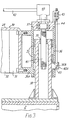
- the capping machine illustrated therein is a vapour vacuum capping machine for the high-speed capping of jars, bottles and other containers using caps which may be of any suitable kind, the machine being adjustable (as will be seen) so that it can handle a wide variety of shapes and sizes of both containers and caps.
- the machine is in use for applying "twist-on, twist-off" metal caps to glass jars filled with a foodstuff.
- the capping machine has a casing comprising a main frame 2 clad with outer panelling 4, to define a working chamber 6, which has a front access opening 8 and a rear access opening not shown. Each of these access openings has doors such as the door shown at 10.
- the main frame 2 supports a conveyor assembly which extends through the capping machine from one side to the other.
- the conveyor assembly includes an endless conveyor 12 of the flat- plate type, having at one end a driving drum 14.
- the conveyor runs on a flat bed 16.
- Below the conveyor 12, within the casing, is a drive motor 22, coupled to a main gearbox 24 which in turn is coupled, through a conveyor drive shaft 26 having a pair of flexible couplings, to the driving gearbox of the conveyor driving drum 14.
- a capping head 28 is arranged within the working chamber 6, over the conveyor 12.
- the capping head 28 has an anodised aluminium body 30 which comprises a horizontal top portion 29, bent to form an apron portion 32 at the left-hand (inlet) end of the head.
- a pair of integral wing portions bent downwardly to form flanges 34 extend outwardly from the top portion 29.
- an integral mounting bracket 31 extends downwardly from the rear of the top portion 29, an integral mounting bracket 31 extends downwardly.
- a post housing 36 comprises a generally-cylindrical portion mounted coaxially on the post 38 and slidable vertical on the latter.
- the post housing 36 also has an integral, forwardly, extending portion 36A; the mounting bracket 31 of the capping head body is rigidly secured to the portion 36A so that the head body 30 is cantilevered from the post housing 36 and supported thereby. This is the only means of support of the capping head body.
- the facility for sliding vertical movement of the post housing 36 on the post 38 is provided for the purpose of adjusting the head height, i.e. the height at which the capping head 28 is positioned above the conveyor 12.
- This adjustment is made by means of a leadscrew 41 which is mounted rotatably in an upper closure plate 37 of the post housing and which is rotatable by means of a handwheel ( Figure 1) and shaft 42, through a head height adjusting gearbox 40 mounted on the upper closure plate 37.
- the shaft 42 is supported in a bearing (not shown) carried by the head body 30 behind the handwheel.
- the leadscrew 41 engages in a threaded bush 39 secured in the top of the post 38.
- the bore of the cylindrical portion of the post housing 36 is lined with sliding bearing rings 35 which engage the post 38 itself.
- the entire static force due to the weight of the capping head 28, and any dynamic forces transmitted to the post 38 from the capping head during operation of the machine, are supported by the post 38 partly via the bearing rings 35 and partly via the leadscrew 41 and bush 39.
- a locking device mounted on the outside of the head housing 36, to prevent any vertical movement of the capping head taking place due to accidental rotation of the leadscrew 41 (which could for example occur as a result of either inadvertent operation of the handwheel on the shaft 42, or mechanical vibration).
- the locking device comprises a long, slender locking pin 44 which has a threaded portion carried by a release nut 43, the latter being captive on the head housing 36.
- the pin 44 extends downwardly from the nut 43 and carries at its lower end a wedge member 45 having a vertical face for frictional locking engagement with the post 38.
- the wedge member 45 also has an inclined face engagin a fixed cam element 45A which is part of the post housing 36.
- the wedge member extends through a slot 36B formed in the side of the post housing. Rotation of the adjusting nut 43, such as to raise the locking pin 44, releases the wedge member from frictional locking engagement between the cam element 45A and post 38, thus allowing the capping head 28 to be raised or lowered.
- cap heating tunnel 54 mounted on the capping head body 30, at the inlet end, is a cap heating tunnel 54 provided with means, not shown, for preheating the caps before the latter are delivered to the containers to be closed.
- An inclined cap feed chute extends downwardly through the tunnel 54 from a suitable supply chute, not shown, which extends through an opening in a portion of the roof of the machine casing 4 that is cut away in Figure 1.
- the lower part 46 of the cap feed chute comprises an assembly which is indicated diagrammatically in Figure 1 and shown in more detail in Figure 2 and Figures 4 to 7. This assembly 46 will be referred to hereinafter simply as the "cap chute". It will be described more fully hereinafter.
- a sealing head assembly 48 Forward of the cap chute 46 is a sealing head assembly 48, carried by the capping head body 30.
- a pair of endless side belts 50 are carried, one either side of the capping head, by the sealing head assembly which will be described hereinafter.
- a vacuum (as hereinbefore explained) is maintained in the region below the capping head body 30 by suitable means, being controllable by a main vacuum control valve 52, Figure 1, mounted on top of the body 30.
- suitable means being controllable by a main vacuum control valve 52, Figure 1, mounted on top of the body 30.
- the vacuum and the means for creating and maintaining it can be conventional; they form no part of the present invention, and no further discussion of these aspects will be undertaken herein.
- filled jars 56 are carried by the conveyor 12 through the inlet tunnel 18 into the working chamber 6, in which each jar first receives a cap, placed upon it at the placement or pick-up position 58 by the cap chute 46. The cap is then secured and sealed upon the jar by the sealing head assembly 48, before being carried out of the working chamber through the exit tunnel 20.
- Each jar is centralised on the conveyor 12 by a pair of adjustable guides 60, Figure 1, overlying the conveyor in the inlet tunnel 18. Immediately after this, the jars are engaged by the side belts 50 which maintain the jars in their straight central path throughout the capping process.
- the cap chute 46 comprises a pair of cap support rails 62, of gradually decreasing inclination to the horizontal in the usual manner.
- Each cap support rail 62 has a side wall 64 and a cap-supporting portion 65, the side walls 64 being spaced apart by slightly more than the diameter of a cap.
- the final section 65A of each of the cap-supporting portions 65 is narrower than the remainder of the portion 65 upstream of the section 65A, so as to provide a suitable gap (indicated at 66 in Figure 4) for the passage of the necks of the successive jars through the gap 66.
- the cap chute is adjustably mounted on a portion 176 ( Figure 6) of the capping body 30, in the following manner.
- a mounting block 172 Secured by studs 174 to the body portion 176 is a mounting block 172 carrying a transverse pivot pin 178 which passes through a bifurcated centre beam 182 of the cap chute. In this way the latter is hung from the mounting block 172.
- the pin 178 carries a nut securing the cap chute to the block 172.
- the mounting block also includes a bracket 184 associated with an adjustment lever 186 which is fixed to the cap chute centre beam 182.
- the bracket 184 carries an adjusting screw 188 whereby the spacing between the lever 186 and bracket 184, maintained by a compression spring 190, is adjustable when the pivot pin nut 180 is loosened. In this manner the altitude of the cap chute is adjustable to obtain the required angle of the cap chute section 65A to the horizontal, for feeding the caps 76 to the jars.
- the centre beam has a width-adjusting shaft 192 mounted through the beam; the shaft 192 has opposed left- and right-hand screw threaded portions, each in screw-threaded engagement with a suitable bracket portion of a respective one of two cap chute side plates 194, so that when the shaft 192 is rotated the side plates are moved towards or away from each other.
- a pair of stretchers 196 provide the main means for securing the side plates 194 together by means of clamping screws 198, the latter being released to allow the width between the side plates to be altered when necessary.
- Each cap support rail 62 is fixed to the adjacent one of the side plates 194. It can be seen from the foregoing how the rails 62 are mounted so as to be readily adjustable both for transverse width bew- een them, so that the cap chute can be re-set to accommodate caps of different diameters; and for the optimum altitude in a vertical plane.
- Each support rail side wall 64 has on its outer surface a mounting bracket 63 carrying a pivot 72 whereby the rear end of a cap stop roller arm or lever 70 is pivoted about a vertical axis.
- the roller arms 70 extend forwardly for some distance, the forward end portion 71 of each arm being directed inwardly through an aperture 67 in the side wall 64; at the free end of the end portion 71, each roller arm carries a cap stop roller 74, which is freely rotatable about its own axis.
- the axes of the stop rollers 74 are so orientated as to lie parallel to each other and substantially parallel to the axis of a cap 76 when the latter is lying, as shown in Figure 4, with its skirt engaging the two stop rollers.
- each cap in turn is arrested by the rollers 74 in its gravity-induced slide down the cap chute; in this position also, the cap becomes engaged by its jar 56 for the first time.
- the stop rollers 74 overlie the final section 65A of the cap-supporting rail portions 65, the rollers protruding through the apertures 67. They are biassed towards this normal position by tension springs 78 connected between the respective roller arms 70 and the associated side walls 64.
- the springs 78 are mounted on top of the respective side walls 64, in an exposed position in which they are readily available for inspection and, if necessary, replacement.
- a pin 202 Attached by a spring clip 200 to the mounting block bracket 184 is a pin 202 on which one end of a pair of arms 82 and 88 are freely pivoted.
- the other end of the arm 82 is pivoted to a vertical push rod 83 carrying a rear presser foot 80.
- the other end of the arm 88 carries a forward presser foot 86; the arm 88 is pivoted about half-way along its length to a vertical push rod 85.
- the presser feet and their linkages are omitted for clarity from Figure 7.
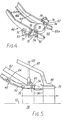
- FIG. 5 The operation of placing a cap 76 upon a jar 56 at the pick-up station 58 is illustrated in Figure 5, in which the cap is indicated, in the same position as in Figure 4, by full lines. Behind it there are indicated in phantom lines, some following caps in the cap chute, awaiting their turn for placement.
- the cap 76 at the pick-up station is held down against the cap-supporting portions 65 of the rails 62 by the rear presser foot 80.
- the pressure exerted on the cap 76 by the presser foot 80 is adjustable, through the push rod 83, by means of an adjuster 92 ( Figure 2) mounted on top of the body 30.
- the rear portion of the cap skirt falls on to the top of the jar.
- the cap Immediately after the cap has left the cap chute, it is restrained laterally by resilient side guides 89 carried by the cap chute side plates 194 ( Figures 2, 6 and 7), and axially by the forward presser shoe 86.
- the axial pressure exerted by the forward presser shoe 86 upon the cap 76 is adjustable in the same manner as that exerted by the rear presser shoe 80, as described above, by a similar adjuster 90 ( Figure 2) acting through the push rod 85.
- Each endless side belt 50 presenting a working or jar-engaging portion 94 and an outer or idle portion 96 ( Figure 2) is carried by a pair of side belt pulleys 98,100, one at each extreme end of the capping head.
- the rear side belt pulleys 98 are freely rotatable, on vertical axes, at the ends of support arms 102 which are pivoted to a cross-beam 104.
- the support arms 102 are biassed by side belt tensioning springs 106.
- the cross-beam 104 is fixed at each of its ends to the rear end of a respective one of a pair of side belt frames or support beams 108 extending along the capping head at either side of the latter.
- Each support beam 108 carries a plurality of side belt locating shoes 110 along which the working portion 94 of the side belt runs.
- each support beam 108 there are two locating shoes 110 to each support beam 108.
- the locating shoes 110 at each side of the capping head serve to maintain the working portion 94 of the respective side belt in a straight configuration and at the correct transverse distance from the working portion of the other belt 50.
- the transverse distances of the locating shoes 110 from their side belt support beams 108 are adjustable by means of suitable adjusters 112, Figure 2.
- the leading side belt pulleys 100 are each carried by a respective side belt pulley gearbox 114 fixed to the front end of the corresponding support beam 108.
- the pulley gearboxes 114 are coupled together by a transverse final drive shaft 116 which is driven by a chain drive 118 from a main driven shaft 120.
- the shaft 120 is cantilevered from a spiral-bevel gearbox 122 mounted at the back of the capping head body 30.
- the gearbox 122 is driven by a vertical main drive shaft 124 which is, in turn, driven by the main gearbox 24, so that the driven shaft 120 and the side belts 50 are all driven, in synchronism with the conveyor 12, by the motor 22.
- Each beam 108 carries two pivots 126, one near each end of the beam. These four pivots lie in a common horizontal plane which is parallel with the top of the conveyor 12. Pivoted at the pivots 126 to the beams 108, and thus connecting the latter together transversely, are two rigid cross-members 128,130.
- the rearward cross-member 128 has a transversely-extending portion joining a pair of side crank portions 132,134, each of which carries the appropriate element of the respective pivot 126 and is also pivoted about a transverse axis (common to the pivots of both crank portions) to the capping head body 30 as indicated at 136.
- the rear crank portion 134 has an upstanding portion to which is pivoted one end of a horizontal tie bar 138.
- the forward cross-member 130 also comprises a transversely-extending portion joining a pair of side crank portions, each pivoted to the beam 108 by the respective pivot 126 and also being pivoted to the capping head body 30 about a transverse axis at 140.
- the axes 136 and 140 lie in a common horizontal plane which is again parallel to the top of the conveyor 12.
- the front end of the horizontal tie bar 138 is pivoted to the transverse portion of the forward cross-member 130.
- the tie bar 138 has a threaded portion 142, which passes through a U-shaped bracket 144 secured to the top of the capping head body 30.
- An adjusting nut 146 is threaded on to the portion 142 and held captive in the bracket 144.
- the side belt support beams 108 are carried in the capping head by a parallelogram-type linkage comprising the beams themselves as lower horizontal members, the tie bar 138 as the upper horizontal member, and, as the side members, the cross members 128 and 130.
- the vertical distance between the side belts 50 and the top of the conveyor 12 (the "side belt height") is infinitely adjustable within a predetermined range by simply turning the nut 146 by means of a spanner, so as to move the tie bar 138 to the right (as seen in Figures 8 and 9) to lower the side belts, and to the left in order to raise them.
- the use of the chain drive 118 enables this adjustment to be made without disturbing the motion of the side belts 50.
- Figures 8 and 9 show two containers of different shapes on the conveyor 12, each container having a cylindrical portion in a different position, and the side belts being adjusted in each case to engage that cylindrical portion.
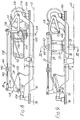
- the sealing head assembly comprises a pair of sealing belt drums 148, 150, of slightly different diameters, carried by the main driven shaft 120 already described, and therefore rotated continuously in synchronism with the conveyor 12 and the side belts 50.
- a pair of endless sealing belts 152,154 extend around the respective drums 148,150 and around respective, rearwardly- disposed, idler pulleys 156.
- the pulleys 156 are carried by brackets 157 ( Figure 2) which are carried, via a spring-tensioning device, not shown, to maintain tension in the belts 152 and 154, by a sealing shoe 158.
- the brackets 157 are omitted from Figures 10 and 11 for clarity.
- the sealing shoe 158 extends generally horizontally and has a flat lower surface overlying, and in contact with, the lower runs of both of the sealing belts 152 and 154.
- the sealing shoe is pivoted to the forward end of each of a forward suspension arm 160 and a rearward suspension arm 162. Both of these suspension arms are pivoted, at their rear ends 164, to the capping head body 30. (These pivots are out of sight in Figure 2).
- the springs 168 cause the sealing shoe 158 to exert upon the caps 76, through the sealing belts 152 and 154, the axial force necessary to secure the caps to the jars 56.
- This force is adjustable by means of spring adjusters 170 ( Figure 2) incorporated in the mountings of the compression springs 168.
- spring adjusters 170 Figure 2 incorporated in the mountings of the compression springs 168.
- Figure 11 (a) illustrates by a heavy arrow the upward reaction force, compressing the rear spring 168, imposed upon the sealing head assembly when a container, carrying a cap, initially arrives under the sealing shoe; whilst Figure 11 (b) illustrates by a similar arrow the reaction force when the capped container is about to pass from below the sealing shoe.
- Figure 11 (b) illustrates by a similar arrow the reaction force when the capped container is about to pass from below the sealing shoe.
Landscapes
- Mechanical Engineering (AREA)
- Engineering & Computer Science (AREA)
- Sealing Of Jars (AREA)
- Glass Compositions (AREA)
- Steering Control In Accordance With Driving Conditions (AREA)
- Injection Moulding Of Plastics Or The Like (AREA)
- Closing Of Containers (AREA)
- Auxiliary Devices For And Details Of Packaging Control (AREA)
- Vending Machines For Individual Products (AREA)
- Medicinal Preparation (AREA)
- Making Paper Articles (AREA)
- Lubricants (AREA)
- Mixers With Rotating Receptacles And Mixers With Vibration Mechanisms (AREA)
- Formation And Processing Of Food Products (AREA)
- Details Of Garments (AREA)
- Diaphragms For Electromechanical Transducers (AREA)
- Meat, Egg Or Seafood Products (AREA)
- Cookers (AREA)
- Soundproofing, Sound Blocking, And Sound Damping (AREA)
- Sealing Devices (AREA)
- Closures For Containers (AREA)
- Supplying Of Containers To The Packaging Station (AREA)
Priority Applications (1)
| Application Number | Priority Date | Filing Date | Title |
|---|---|---|---|
| AT86200037T ATE42728T1 (de) | 1982-08-17 | 1983-08-04 | Verschliessmaschinen. |
Applications Claiming Priority (2)
| Application Number | Priority Date | Filing Date | Title |
|---|---|---|---|
| GB08223653A GB2125379B (en) | 1982-08-17 | 1982-08-17 | Capping machines |
| GB8223653 | 1982-08-17 |
Related Parent Applications (1)
| Application Number | Title | Priority Date | Filing Date |
|---|---|---|---|
| EP83304502.4 Division | 1983-08-04 |
Publications (3)
| Publication Number | Publication Date |
|---|---|
| EP0184583A2 EP0184583A2 (en) | 1986-06-11 |
| EP0184583A3 EP0184583A3 (en) | 1987-08-26 |
| EP0184583B1 true EP0184583B1 (en) | 1989-05-03 |
Family
ID=10532355
Family Applications (2)
| Application Number | Title | Priority Date | Filing Date |
|---|---|---|---|
| EP86200037A Expired EP0184583B1 (en) | 1982-08-17 | 1983-08-04 | Capping machines |
| EP83304502A Expired EP0103389B1 (en) | 1982-08-17 | 1983-08-04 | Capping machines |
Family Applications After (1)
| Application Number | Title | Priority Date | Filing Date |
|---|---|---|---|
| EP83304502A Expired EP0103389B1 (en) | 1982-08-17 | 1983-08-04 | Capping machines |
Country Status (19)
| Country | Link |
|---|---|
| US (1) | US4608806A (da) |
| EP (2) | EP0184583B1 (da) |
| JP (2) | JPS5984788A (da) |
| AT (1) | ATE42728T1 (da) |
| AU (2) | AU555562B2 (da) |
| CA (1) | CA1215694A (da) |
| DD (1) | DD215519A5 (da) |
| DE (1) | DE3374554D1 (da) |
| DK (1) | DK156048C (da) |
| ES (1) | ES525552A0 (da) |
| FI (1) | FI77002C (da) |
| GB (1) | GB2125379B (da) |
| GR (1) | GR79633B (da) |
| HU (1) | HUH3044A (da) |
| IE (1) | IE54565B1 (da) |
| NO (2) | NO161435C (da) |
| PL (1) | PL138677B1 (da) |
| PT (1) | PT77201B (da) |
| SU (2) | SU1537132A3 (da) |
Families Citing this family (20)
| Publication number | Priority date | Publication date | Assignee | Title |
|---|---|---|---|---|
| GB8901460D0 (en) * | 1989-01-24 | 1989-03-15 | Glover Clive E | Capping device |
| US5012630A (en) * | 1990-03-01 | 1991-05-07 | Owens-Illinois Closure Inc. | Closure application system |
| US5218811A (en) * | 1992-05-27 | 1993-06-15 | Diversified Capping Equipment, Inc. | Closure pre-tightening mechanism for a container filling and capping system |
| US6941724B2 (en) * | 2001-06-07 | 2005-09-13 | Klockner Khs, Inc. | Screw capping head |
| DE10352016B3 (de) * | 2003-11-07 | 2005-08-11 | Khs Maschinen- Und Anlagenbau Ag | Verschließmaschine zum Verschließen von Gefäßen |
| US7032363B1 (en) * | 2004-10-19 | 2006-04-25 | Tetra Laval Holdings & Finance, Sa | Linear fitment applicator and method |
| US7325369B2 (en) * | 2006-02-21 | 2008-02-05 | Luc Jalbert | Apparatus including a differential for rotating a cap relatively to a container |
| JP2010070248A (ja) * | 2008-09-22 | 2010-04-02 | Shibuya Kogyo Co Ltd | キャッパ |
| IT1395607B1 (it) * | 2009-09-14 | 2012-10-16 | Ft System Srl | Impianto di riempimento di bottiglie o contenitori a taratura continua e metodo di taratura in continuo di un tale impianto |
| ES2431267B1 (es) * | 2013-05-24 | 2014-09-10 | José Francisco González Sánchez | Utillaje para el montaje de una tapa de protección en un envase y un método para colocar una tapa protectora en un envase |
| US9751741B2 (en) * | 2014-07-23 | 2017-09-05 | Xentiq Partners Pte Ltd | Dispensing apparatus, method of dispensing, capping apparatus and method of capping |
| US10351405B2 (en) * | 2016-02-11 | 2019-07-16 | NJM Packaging Inc. | Capping machine |
| EP3205589B1 (en) * | 2016-02-12 | 2019-04-03 | Tetra Laval Holdings & Finance S.A. | A distribution unit for feeding lids to necks of containers |
| US20180346158A1 (en) * | 2017-06-02 | 2018-12-06 | Inline Plastics Corp. | Closure Systems and Methods For Containers |
| WO2022197318A1 (en) * | 2021-03-18 | 2022-09-22 | Vonco Products, Llc | Cap for spout and modified spout |
| IT202100014288A1 (it) * | 2021-06-01 | 2022-12-01 | Sasib Spa | Macchina per il confezionamento di prodotti dell’industria del tabacco |
| CN113979393A (zh) * | 2021-09-14 | 2022-01-28 | 苏州得一鲜食品科技有限公司 | 一种食品罐的封装设备及封装方法 |
| US11993414B2 (en) | 2021-12-13 | 2024-05-28 | Boomerang Water, Llc | Cleaning, filling, and capping containers |
| FR3139805B1 (fr) * | 2022-09-20 | 2025-01-17 | Coudert Constructions | Dispositif pour le vissage d’une capsule sur un corps d’emballage |
| CN115991452B (zh) * | 2023-03-22 | 2023-06-27 | 江苏尚纯自动化技术有限公司 | 一种压盖高度可调的包装机 |
Family Cites Families (20)
| Publication number | Priority date | Publication date | Assignee | Title |
|---|---|---|---|---|
| CA597618A (en) * | 1960-05-10 | L. Day Carl | Container sealing apparatus | |
| GB394480A (en) * | 1931-06-03 | 1933-06-29 | Standard Cap & Seal Corp | Improvements in bottle capping mechanism |
| US2256415A (en) * | 1938-08-19 | 1941-09-16 | Crown Cork & Seal Co | Container sealing apparatus |
| US2319214A (en) * | 1940-04-17 | 1943-05-18 | White Cap Co | Sealing apparatus |
| GB646441A (en) * | 1946-09-20 | 1950-11-22 | Anchor Hocking Glass Corp | Improvements relating to machines for applying and sealing closure caps to bottles, jars, cans and like containers |
| US2876605A (en) * | 1958-06-19 | 1959-03-10 | White Cap Co | Machine for applying rotatable closure caps to containers |
| US3054234A (en) * | 1960-02-05 | 1962-09-18 | Anchor Hocking Glass Corp | Sealing machine and method |
| US3071909A (en) * | 1960-04-22 | 1963-01-08 | Anchor Hocking Glass Corp | Screw cap applicator |
| US3274748A (en) * | 1963-05-10 | 1966-09-27 | Anchor Hocking Glass Corp | Sealing machine and method |
| US3438174A (en) * | 1965-02-11 | 1969-04-15 | Anchor Hocking Glass Corp | Container sealing machine |
| GB1071008A (en) * | 1965-11-17 | 1967-06-07 | Skane Emballage Ab | A device for placing threaded closures on containers |
| US3559365A (en) * | 1968-02-27 | 1971-02-02 | Haskon Inc | Capping apparatus and method |
| US3800501A (en) * | 1972-02-03 | 1974-04-02 | Continental Can Co | Cap feeding apparatus |
| US3803800A (en) * | 1973-02-09 | 1974-04-16 | Neuvelle Baele Gangloff Racine | Device for fitting bottle and container caps |
| US3905177A (en) * | 1973-10-29 | 1975-09-16 | Michael Herzog | Bottle capping machine |
| SU571432A1 (ru) * | 1975-12-18 | 1977-09-05 | Всесоюзный Научно-Исследовательский Кинофотоинститут | Устройство дл закрывани крышками цилиндрических сосудов |
| US4199914A (en) * | 1978-09-08 | 1980-04-29 | Anchor Hocking Corporation | Sealing machine closure cap pickup |
| SE7908966L (sv) * | 1978-11-15 | 1980-05-16 | Schmalbach Lubeca | Anordning for applicering av skruvlock/-kapsyler pa forvaringskerl |
| US4279115A (en) * | 1979-03-12 | 1981-07-21 | Anchor Hocking Corporation | High speed straight line container sealing machine |
| IT1163993B (it) * | 1979-05-08 | 1987-04-08 | Italcaps Spa | Procedimento per la precchiusura con capsule di vasi contenenti prodotti eventualmente debordanti e dispositivo per realizzarla |
-
1982
- 1982-08-17 GB GB08223653A patent/GB2125379B/en not_active Expired
-
1983
- 1983-08-04 EP EP86200037A patent/EP0184583B1/en not_active Expired
- 1983-08-04 EP EP83304502A patent/EP0103389B1/en not_active Expired
- 1983-08-04 DE DE8383304502T patent/DE3374554D1/de not_active Expired
- 1983-08-04 AT AT86200037T patent/ATE42728T1/de not_active IP Right Cessation
- 1983-08-08 US US06/521,107 patent/US4608806A/en not_active Expired - Fee Related
- 1983-08-09 AU AU17817/83A patent/AU555562B2/en not_active Ceased
- 1983-08-11 GR GR72195A patent/GR79633B/el unknown
- 1983-08-12 IE IE1900/83A patent/IE54565B1/en not_active IP Right Cessation
- 1983-08-12 PT PT77201A patent/PT77201B/pt not_active IP Right Cessation
- 1983-08-16 NO NO832942A patent/NO161435C/no unknown
- 1983-08-16 DK DK375183A patent/DK156048C/da not_active IP Right Cessation
- 1983-08-16 SU SU833650403A patent/SU1537132A3/ru active
- 1983-08-16 FI FI832943A patent/FI77002C/fi not_active IP Right Cessation
- 1983-08-16 CA CA000434730A patent/CA1215694A/en not_active Expired
- 1983-08-16 HU HU832881A patent/HUH3044A/hu unknown
- 1983-08-17 DD DD83254034A patent/DD215519A5/de unknown
- 1983-08-17 ES ES525552A patent/ES525552A0/es active Granted
- 1983-08-17 PL PL1983243446A patent/PL138677B1/pl unknown
- 1983-08-17 JP JP58149270A patent/JPS5984788A/ja active Granted
-
1985
- 1985-04-29 SU SU853888448A patent/SU1398769A3/ru active
- 1985-09-26 NO NO853788A patent/NO853788L/no unknown
-
1986
- 1986-04-11 AU AU56032/86A patent/AU572390B2/en not_active Ceased
-
1987
- 1987-09-16 JP JP62229942A patent/JPS63178984A/ja active Pending
Also Published As
Similar Documents
| Publication | Publication Date | Title |
|---|---|---|
| EP0184583B1 (en) | Capping machines | |
| US4199914A (en) | Sealing machine closure cap pickup | |
| US3905177A (en) | Bottle capping machine | |
| US3438174A (en) | Container sealing machine | |
| US2876605A (en) | Machine for applying rotatable closure caps to containers | |
| US3874147A (en) | Device for guiding and/or preliminary tightening of caps in an apparatus for closing jars or other containers with caps | |
| US3012388A (en) | Means for sealing threaded-type containers | |
| US4559760A (en) | Universal capping machine | |
| US2319213A (en) | Packaging apparatus | |
| US2656084A (en) | Jar-handling equipment for capping machines | |
| US3435587A (en) | Self-adjusting cap applying mechanism | |
| US3850284A (en) | Container sealing machine side belt system | |
| US2942394A (en) | Container closing apparatus | |
| CA1228579A (en) | Capping machines | |
| GB2161150A (en) | Capping machines | |
| US3623292A (en) | Capping machine | |
| US3175337A (en) | Container headspacer | |
| US2169973A (en) | Apparatus for feeding and applying closure caps | |
| US3879921A (en) | Overcap seater for aerosol containers | |
| US2735600A (en) | Apparatus for sealing containers | |
| FI77003B (fi) | Foerslutningsmaskin foer anbringande av loestagbara tillslutningsdelar pao behaollare. | |
| JP7455306B2 (ja) | キャッパー | |
| GB2045731A (en) | Closure application machine |
Legal Events
| Date | Code | Title | Description |
|---|---|---|---|
| PUAI | Public reference made under article 153(3) epc to a published international application that has entered the european phase |
Free format text: ORIGINAL CODE: 0009012 |
|
| 17P | Request for examination filed |
Effective date: 19860122 |
|
| AC | Divisional application: reference to earlier application |
Ref document number: 103389 Country of ref document: EP |
|
| AK | Designated contracting states |
Kind code of ref document: A2 Designated state(s): AT BE CH DE FR GB IT LI LU NL SE |
|
| RIN1 | Information on inventor provided before grant (corrected) |
Inventor name: HASLAM, JAMES KEITH Inventor name: HASLAM, JAMES KEITH MAY COTTAGE PICCADILLY LANE |
|
| PUAL | Search report despatched |
Free format text: ORIGINAL CODE: 0009013 |
|
| AK | Designated contracting states |
Kind code of ref document: A3 Designated state(s): AT BE CH DE FR GB IT LI LU NL SE |
|
| 17Q | First examination report despatched |
Effective date: 19880902 |
|
| GRAA | (expected) grant |
Free format text: ORIGINAL CODE: 0009210 |
|
| RAP1 | Party data changed (applicant data changed or rights of an application transferred) |
Owner name: MB GROUP PLC |
|
| AC | Divisional application: reference to earlier application |
Ref document number: 103389 Country of ref document: EP |
|
| AK | Designated contracting states |
Kind code of ref document: B1 Designated state(s): AT BE CH DE FR GB IT LI LU NL SE |
|
| PG25 | Lapsed in a contracting state [announced via postgrant information from national office to epo] |
Ref country code: SE Effective date: 19890503 Ref country code: CH Effective date: 19890503 Ref country code: BE Effective date: 19890503 Ref country code: AT Effective date: 19890503 Ref country code: IT Free format text: LAPSE BECAUSE OF FAILURE TO SUBMIT A TRANSLATION OF THE DESCRIPTION OR TO PAY THE FEE WITHIN THE PRE;WARNING: LAPSES OF ITALIAN PATENTS WITH EFFECTIVE DATE BEFORE 2007 MAY HAVE OCCURRED AT ANY TIME BEFORE 2007. THE CORRECT EFFECTIVE DATE MAY BE DIFFERENT FROM THE ONE RECORDED.SCRIBED TIME-LIMIT Effective date: 19890503 Ref country code: NL Effective date: 19890503 Ref country code: FR Free format text: THE PATENT HAS BEEN ANNULLED BY A DECISION OF A NATIONAL AUTHORITY Effective date: 19890503 Ref country code: LI Effective date: 19890503 |
|
| REF | Corresponds to: |
Ref document number: 42728 Country of ref document: AT Date of ref document: 19890515 Kind code of ref document: T |
|
| REF | Corresponds to: |
Ref document number: 3379785 Country of ref document: DE Date of ref document: 19890608 |
|
| REG | Reference to a national code |
Ref country code: CH Ref legal event code: PL |
|
| PG25 | Lapsed in a contracting state [announced via postgrant information from national office to epo] |
Ref country code: LU Free format text: LAPSE BECAUSE OF NON-PAYMENT OF DUE FEES Effective date: 19890831 |
|
| EN | Fr: translation not filed | ||
| NLV1 | Nl: lapsed or annulled due to failure to fulfill the requirements of art. 29p and 29m of the patents act | ||
| PLBE | No opposition filed within time limit |
Free format text: ORIGINAL CODE: 0009261 |
|
| STAA | Information on the status of an ep patent application or granted ep patent |
Free format text: STATUS: NO OPPOSITION FILED WITHIN TIME LIMIT |
|
| 26N | No opposition filed | ||
| PG25 | Lapsed in a contracting state [announced via postgrant information from national office to epo] |
Ref country code: DE Effective date: 19900501 |
|
| PGFP | Annual fee paid to national office [announced via postgrant information from national office to epo] |
Ref country code: GB Payment date: 19910712 Year of fee payment: 9 |
|
| PG25 | Lapsed in a contracting state [announced via postgrant information from national office to epo] |
Ref country code: GB Effective date: 19920804 |
|
| GBPC | Gb: european patent ceased through non-payment of renewal fee |
Effective date: 19920804 |