EP3205589B1 - A distribution unit for feeding lids to necks of containers - Google Patents
A distribution unit for feeding lids to necks of containers Download PDFInfo
- Publication number
- EP3205589B1 EP3205589B1 EP16155511.5A EP16155511A EP3205589B1 EP 3205589 B1 EP3205589 B1 EP 3205589B1 EP 16155511 A EP16155511 A EP 16155511A EP 3205589 B1 EP3205589 B1 EP 3205589B1
- Authority
- EP
- European Patent Office
- Prior art keywords
- active portion
- lid
- containers
- neck
- container
- Prior art date
- Legal status (The legal status is an assumption and is not a legal conclusion. Google has not performed a legal analysis and makes no representation as to the accuracy of the status listed.)
- Active
Links
Images
Classifications
-
- B—PERFORMING OPERATIONS; TRANSPORTING
- B65—CONVEYING; PACKING; STORING; HANDLING THIN OR FILAMENTARY MATERIAL
- B65B—MACHINES, APPARATUS OR DEVICES FOR, OR METHODS OF, PACKAGING ARTICLES OR MATERIALS; UNPACKING
- B65B7/00—Closing containers or receptacles after filling
- B65B7/16—Closing semi-rigid or rigid containers or receptacles not deformed by, or not taking-up shape of, contents, e.g. boxes or cartons
- B65B7/28—Closing semi-rigid or rigid containers or receptacles not deformed by, or not taking-up shape of, contents, e.g. boxes or cartons by applying separate preformed closures, e.g. lids, covers
- B65B7/2807—Feeding closures
-
- B—PERFORMING OPERATIONS; TRANSPORTING
- B65—CONVEYING; PACKING; STORING; HANDLING THIN OR FILAMENTARY MATERIAL
- B65B—MACHINES, APPARATUS OR DEVICES FOR, OR METHODS OF, PACKAGING ARTICLES OR MATERIALS; UNPACKING
- B65B65/00—Details peculiar to packaging machines and not otherwise provided for; Arrangements of such details
-
- B—PERFORMING OPERATIONS; TRANSPORTING
- B65—CONVEYING; PACKING; STORING; HANDLING THIN OR FILAMENTARY MATERIAL
- B65B—MACHINES, APPARATUS OR DEVICES FOR, OR METHODS OF, PACKAGING ARTICLES OR MATERIALS; UNPACKING
- B65B7/00—Closing containers or receptacles after filling
- B65B7/16—Closing semi-rigid or rigid containers or receptacles not deformed by, or not taking-up shape of, contents, e.g. boxes or cartons
- B65B7/28—Closing semi-rigid or rigid containers or receptacles not deformed by, or not taking-up shape of, contents, e.g. boxes or cartons by applying separate preformed closures, e.g. lids, covers
- B65B7/2835—Closing semi-rigid or rigid containers or receptacles not deformed by, or not taking-up shape of, contents, e.g. boxes or cartons by applying separate preformed closures, e.g. lids, covers applying and rotating preformed threaded caps
-
- B—PERFORMING OPERATIONS; TRANSPORTING
- B67—OPENING, CLOSING OR CLEANING BOTTLES, JARS OR SIMILAR CONTAINERS; LIQUID HANDLING
- B67B—APPLYING CLOSURE MEMBERS TO BOTTLES JARS, OR SIMILAR CONTAINERS; OPENING CLOSED CONTAINERS
- B67B3/00—Closing bottles, jars or similar containers by applying caps
- B67B3/20—Closing bottles, jars or similar containers by applying caps by applying and rotating preformed threaded caps
- B67B3/204—Linear-type capping machines
-
- B—PERFORMING OPERATIONS; TRANSPORTING
- B67—OPENING, CLOSING OR CLEANING BOTTLES, JARS OR SIMILAR CONTAINERS; LIQUID HANDLING
- B67B—APPLYING CLOSURE MEMBERS TO BOTTLES JARS, OR SIMILAR CONTAINERS; OPENING CLOSED CONTAINERS
- B67B2201/00—Indexing codes relating to constructional features of closing machines
- B67B2201/06—Details of cap feeding devices
Definitions
- the invention relates to a distribution unit for feeding lids to necks of containers, particularly sealed containers for packaging pourable food products.
- the distribution unit according to the invention is especially suitable for applying a lid onto a neck that has been moulded on a sheet packaging material, the latter being in turn adapted to be folded, filled with a pourable food product and sealed to form a container.
- pourable food products such as fruit juice, UHT (ultra-high-temperature treated) milk, wine, tomato sauce, etc.
- containers made of sterilized sheet packaging material are sold in containers made of sterilized sheet packaging material.
- Tetra Brik Aseptic registered trademark
- a typical example of this type of containers is the parallelepiped-shaped container for liquid or pourable food products known as Tetra Brik Aseptic (registered trademark), which is made by folding and sealing laminated strip packaging material.
- the packaging material has a multilayer structure substantially comprising a base layer for stiffness and strength, which may include a layer of fibrous material, e.g. paper, or mineral-filled polypropylene material, and a number of lamination layers of heat-sealable plastic material, e.g. polyethylene films, covering both sides of the base layer.
- a base layer for stiffness and strength may include a layer of fibrous material, e.g. paper, or mineral-filled polypropylene material, and a number of lamination layers of heat-sealable plastic material, e.g. polyethylene films, covering both sides of the base layer.
- the packaging material also comprises a layer of gas-barrier material, e.g. aluminium foil or ethyl vinyl alcohol (EVOH) film, which is superimposed on a layer of heat-sealable plastic material, and is in turn covered with another layer of heat-sealable plastic material forming the inner face of the container eventually contacting the food product.
- gas-barrier material e.g. aluminium foil or ethyl vinyl alcohol (EVOH) film
- Containers of this sort are normally produced on fully automatic packaging machines, which are fed with a web of packaging material that is sterilized in the packaging machine, e.g. by applying a chemical sterilizing agent, such as a hydrogen peroxide solution, which, once sterilization is completed, is removed from the surfaces of the packaging material, e.g. evaporated by heating.
- a chemical sterilizing agent such as a hydrogen peroxide solution
- the web of packaging material so sterilized is then maintained in a closed, sterile environment, and is folded and sealed longitudinally to form a vertical tube.
- the tube is filled with a sterilized or sterile-processed food product, and is sealed and subsequently cut along equally spaced cross sections to form pillow packs, which are then folded mechanically to form respective finished, e.g. substantially parallelepiped-shaped, containers.
- the packaging material may be cut into blanks, which are formed into containers on forming spindles, and the containers are filled with the food product and sealed.
- a container known by the trade name Tetra Rex (registered trademark).
- the opening of the pouring spout is sealed by a closing element connected integrally to the pouring spout and detachable from it along a normally circular tear line.
- the closing element extends at the same level as the packaging material, so as to seal the hole in the wall of the container.
- the closing element On the side facing the lid, the closing element has an integral projecting pull ring, the free end of which is pulled by the user to detach the closing element from the pouring spout along the tear line and so open the pouring opening. More specifically, the pull ring extends inside, and at a predetermined distance from, the pouring spout.
- a removable, e.g. screw or hinged, lid is subsequently fitted to the pouring spout in order to outwardly close the latter.
- the closing element of the opening device is formed in one piece with a protruding portion extending inside the pouring spout and welded to the lid.
- the latter is provided with a disk-shaped welding promoting element that is welded to the protruding portion so that, when removing the lid from the pouring spout, the protruding portion and the closing element remain attached to the lid.
- each container When coming out from the filling machine, each container has a neck that defines the pouring spout. The neck is closed by a respective closing element, and protrudes from a top wall of the container.
- an applying unit for applying lids to the necks of the containers.
- the applying unit comprises a conveyor along which the containers are advanced and wherein a lid is placed on a respective neck and a capping unit that screws the lid onto the neck.
- Distribution units are known that delivers a lid to a corresponding neck of a container while the container is being advanced by the conveyor.
- the known distribution units comprise a chute containing a row of lids.
- the chute has an outlet projecting on the conveyor so that the neck of the container interacts with the lid closer to the outlet of the chute, i.e. the first lid of the row, and removes the lid from the chute.
- a drawback of these distribution units is that the lid may be incorrectly positioned on the neck. This is due to the fact that the lid is removed from the chute by the moving neck. The removal, therefore, is highly affected by the interaction between the neck and the lid at the outlet of the chute.
- the position of the container with respect to the conveyor can vary - within a certain range of tolerance - from container to container and the position of the lid with respect to the outlet of the chute can vary - within a certain range of tolerance - from lid to lid, the final position of the lid on the container cannot be completely controlled. This may create problems in the capping unit, when the lid has to be screwed on the neck.
- US3755987 discloses a machine for sealingly closing containers each provided with an upper outwardly projecting collar, by means of a cap which is applied on the said collar, comprising container-conveying means adapted to drive the containers along a first circular path, cap-conveying means adapted to convey the containers along a second circular path tangent to the first path and arranged above the latter, so that each cap travelling along the second-path portion is located above a container and moves by gravity onto its collar, and fixing means adapted to secure a cap on each container.
- US2003/159408 dislcoses a cap chute end for capping a plurality of in-line containers in an ambient atmosphere
- a fluid manifold having a plurality of first manifold apertures for injecting a first fluid into the plurality of containers.
- a fluid shoe is operatively adjacent the fluid manifold and has a plurality of shoe apertures for dispensing a second fluid into the plurality of caps and plurality of containers.
- a frame that supports the fluid shoe is configured to receive a plurality of caps at a receiving end of the frame.
- a wiper supported at a dispensing end of the frame has a pair of arms operatively adjacent the fluid shoe. The pair of arms is configured to orient the plurality of caps to the plurality of containers.
- An object of the invention is to improve the distribution units for feeding lids to necks of containers.
- a further object is to improve accuracy of distribution units for feeding lids to necks of containers, without excessively complicating the mechanical structure of the distribution units.
- a further object is to provide a distribution unit that can precisely feed lids to necks of deformable containers, for example container made of packaging material having a multilayer structure.
- a distribution unit for feeding lids to necks of containers as claimed in claim 1.
- Figure 1 shows a lid 1 intended to be applied onto a container neck.
- the lid 1 comprises an end wall 2, which may be shaped as a disk, particularly a circular disk.
- the lid 1 further comprises a side wall 3, which may be substantially cylindrical, appended to the end wall 2.
- the side wall 3 extends around an axis of the lid 1, whereas the end wall 2 extends transversely, in particular perpendicularly, to the axis of the lid 1.
- the side wall 3 is provided with one or more internal threads 4 capable of engaging with corresponding threads obtained on the container neck.
- the side wall 3 may be externally provided with a plurality of knurls 5, which allow a user to more easily grip the lid 1.
- Two appendages 6 project from an outer surface of the side wall 3, at diametrically opposite positions.
- the lid 1 may comprise an annular rib 8, obtained integrally with the end wall 2, which axially protrudes from the end wall 2 towards the inside of the lid 1.
- the annular rib 8 defines a seat for receiving the welding promoting element 7.
- the welding promoting element 7 is defined by a multilayer sheet element distinct from the end wall 2 and permanently connected to the latter.
- the welding promoting element 7 comprises a layer of conductive material, e.g. an aluminium foil, and at least two layers of heat-sealable plastic material, e.g. polyethylene films, covering both sides of the layer of conductive material and defining respective opposite faces of the welding promoting element 7.
- a face of the welding promoting element 7 is welded to the end wall 2 by the heat generated when inducing a current in the layer made of conductive material.
- the lid 1 is intended to be applied onto a neck 9 of a container 10, particularly a sealed container for packaging pourable food products.
- the container can be made of a packaging material having a multilayer structure, as disclosed in the introductory part of this patent application.
- the neck 9 is included in an opening device comprising a pouring spout 11 fixed to the packaging material forming the container 10.
- the neck 9 has a substantially cylindrical tubular shape and extends around an axis A.
- the neck 9 defines a pouring opening 12, through which the content of the container 10 can be poured by a user.
- the lid 1 can be removably coupled to the neck 9.
- the axis of the lid 1 is coincident with the axis A of the neck 9.
- the pouring opening 12 is initially closed by a closing element 14 that is integrally connected to the pouring spout 11 at a tear line 15, along which the closing element 14 can be detached from the pouring spout 11.
- the pouring spout 11 and the closing element 14 are formed in one piece on a receiving portion 16 of the packaging material forming the container 10, whilst the lid 1 is formed separately from the pouring spout 11 and the closing element 14, and then fitted thereto.
- the pouring spout 11 and the closing element 14 may be obtained by moulding molten plastic material - in particular by an injection moulding operation - on the packaging material before it is transformed into a container 10.
- the receiving portion 16 may be defined by a so called pre-laminated hole made in the packaging material forming the container 10, i.e. a hole made through a base layer of the packaging material and covered by one, two, or more lamination layers of the packaging material, which seal the hole.
- the receiving portion 16 may be simply defined by a hole made through the whole thickness of the packaging material forming the container 1, which is intended to be sealed by the pouring spout 11 and the closing element 14.
- the receiving portion 16 may be defined by a patch fixed to the rest of packaging material to seal a hole formed, in this case, through the whole thickness of the packaging material.
- the closing element 14 is formed in one piece with a protruding portion 17 extending through the pouring opening 12.
- the protruding portion 17 is intended to be welded to the welding promoting element 7, after the lid 1 has been screwed onto the neck 9.
- the protruding portion 17 may comprise an annular body 18 for contacting the welding promoting element 7, and two or more legs 19 for connecting the annular body 18 to the closing element 14.
- the legs 19 are diametrically opposite one another.
- the container 10 is formed, filled and sealed in a filling machine and is already provided with the pouring spout 11, the closing element 14 and the protruding portion 17 when leaving the filling machine. Thereafter, as will be described in greater detail hereinbelow, an applying head screws a lid 1 onto the neck 9.
- the welding promoting element 7 of the lid 1 is then welded to the protruding portion 17, by inducing an electric current in the conductive layer of the welding promoting element 7. This current melts the heat-sealable layer of the welding promoting element 7 that faces the neck 9, thereby permanently joining the welding promoting element 7 to the protruding portion 17.
- the first opening of the container 10 is obtained by rotating the lid 1 relative to the pouring spout 11 around the axis A.
- the legs 19 bend in the direction of rotation, thereby exerting a pulling action on the closing element 14 at a given point of the tear line 15.
- the torque exerted on the lid 1 is transformed in a pulling action on the closing element 14, which starts to detach from the pouring spout 11 at two given points along the tear line 15.
- the user can then use the lid 1 to again close or open the container 10, by screwing the lid 1 onto the neck 9 or, respectively, unscrewing the lid 1 from the neck 9, as often as desired.
- Figure 4 shows an applying unit or apparatus 20 for applying lids 1 onto respective containers 10, which have already been formed, filled and sealed in a filling machine provided upstream of the apparatus 20.
- Each container 10 has, in the embodiment shown, a substantially parallelepiped body and a slanted top wall, i.e. a top wall that is inclined with respect to a base wall of the container 10.
- a substantially parallelepiped body and a slanted top wall i.e. a top wall that is inclined with respect to a base wall of the container 10.
- the top wall is inclined with respect to a horizontal plane parallel to the base wall.
- each container 10 has a substantially parallelepiped body and a top wall substantially parallel to the base wall.
- the apparatus 20 may work with containers 10 having different shapes and/or dimensions.
- the apparatus 20 comprises a conveying device 100 (shown in Figures 6 to 9 ) for advancing the containers 10 in an advancement direction F, particularly along a rectilinear path.
- the conveying device 100 comprises a linear conveyor, for example a belt conveyor or a roller conveyor.
- the conveying device 100 is configured to advance the containers 10 continuously along the advancement direction F.
- a sequencing device may be provided, in order to arrange the containers 10 at a preset distance one from another, i.e. in a sequence having a preset pitch. It is thus ensured that the containers 10 are regularly spaced when entering the apparatus 20.
- the apparatus 20 further comprises a distribution unit 101 for feeding the lids 1 to the necks 9 of the containers 10 advancing along the advancement direction F.
- the distribution unit 101 comprises a chute element 102 arranged for receiving a row of lids.
- the distribution unit further comprises a feeding unit, which is not shown, for supplying the lids 1 to the chute element 102.
- the chute element 102 is inclined with respect to the conveying device 100, so that the distance between the chute element 102 and the conveying device 100 decreases when moving along the advancement direction F.
- the chute element 102 has an outlet opening 103 arranged for releasing the lids one at a time.
- the chute element 102 has a couple of flexible retaining element 104 that loosely retains one lid 1, i.e. the first lid of the above-mentioned row.
- the distribution unit 101 is positioned above the conveying device 100 so that each container 10 being advanced by the conveying device 100 interacts with the chute element 102 to remove a corresponding lid 1 from the outlet opening 103.
- the distribution unit 101 further comprises a guide element 105.
- the guide element 105 comprises a fastening portion 107 connected to the chute element 102 by means of connecting elements, for example nuts.
- the guide element 105 comprises an active surface 106 extending on the opposite side of the chute element 102 with respect to the outlet opening 103 and arranged for interacting with the lids 1.
- the active surface 106 faces towards the conveying device 100, i.e. towards the necks 9 on which the lids 2 have to be applied.
- the active surface 106 has a stepped profile.
- the active surface 106 comprises a first active portion 108 arranged downstream of the outlet opening 103 with respect to the advancement direction F.
- the first active portion 108 extends immediately downstream of the outlet opening 103.
- the first active portion 108 is so shaped as to guide the lid 1 during removal from the outlet opening 103 and place the lid 1 in a plane substantially parallel to the top wall of the container 10, i.e. substantially parallel to the plane defined by an upper edge 111 of the neck 9.
- the first active portion 108 defines with a side surface 112 of the guide element 105 a driving element 116 that interacts with the end wall 2 of the lid 1 when the lid 1 is retained by the flexible retaining elements 104 and when the lid 1 is removed from the outlet opening 103.
- the first active portion 108 comprises a first planar face 113 that places the lid 1 in the above-mentioned plane substantially parallel to the top wall of the container 10 and keeps the lid 1 in position when the container 10 that has received the lid 1 is advanced by the conveying device 101.
- the active surface 106 comprises a second active portion 109 arranged downstream of the first active portion 108 with respect to the advancement direction F.
- the second active portion 109 is arranged on the opposite side of the first active portion 108 with respect to the outlet opening 103.
- the second active portion 109 is so shaped as to press the lid 1 on the neck 9 in order to correctly position the lid 1 with respect to the neck 9.
- the top panel of the container 10 may be slightly elastically deformed, i.e. it may pass from a substantially planar configuration to a curved configuration.
- the second active portion 109 comprises a second planar face 114 that causes a preliminary engagement, i.e. before the screwing operation, of the lid 1 on the neck 9, so as to avoid that the lid 1 is tilted with respect to the neck 9 and therefore the subsequent screwing operation is made difficult, or even impossible.
- the active surface 106 comprises a third active portion 110 arranged downstream of the second active portion 109 with respect to the advancement direction F.
- the third active portion 110 is arranged on the opposite side of the second active portion 109 with respect to the first active portion 108.
- the second active portion 109 is interposed between the first active portion 108 and the third active portion 110.
- the third active portion 110 is so shaped as to allow releasing the pressure generated by the second active portion 109 on the lid 1, and therefore on the container 10.
- the third active portion 110 comprises a third planar face 115 that prevents the lid 1 from being expelled from the neck 9 once the second active portion 109 does not pushes the lid 1 on the neck 9 anymore and therefore the top panel of the container 10 moves back from the curved configuration to the substantially planar configuration.
- the first active portion 108 is placed at a first distance d1 from the conveying device 100.
- the second active portion 109 is placed at a second distance d2 from the conveying device 100.
- the third active portion 110 is placed at a third distance d3 from the conveying device 100.
- the first distance d1 is greater than the second distance d2.
- the third distance d3 is greater than the second distance d2.
- the first distance d1 may be different from the third distance d3.
- the guide element 105 further comprises a first connecting portion 117 connecting the first planar face 113 and the second planar face 114.
- the first connecting portion 117 has a slanted, or curved, configuration.
- the distance of the first connecting portion 117 from the conveying device 100 decreases when moving from the first planar face 113 to the second planar face 114, i.e. along the advancement direction F.
- the guide element 105 further comprises a second connecting portion 118 connecting the second planar face 114 and the third planar face 115.
- the second connecting portion 118 has a slanted, or curved, configuration.
- the distance of the second connecting portion 118 from the conveying device 100 increases when moving from the second planar face 114 to the third planar face 115, i.e. along the advancement direction F.
- the first active portion 108 guides the lid 1 during removal from the outlet opening 103 and places the lid 1 in a plane substantially parallel to the top wall of the container 10, i.e. substantially parallel to the plane defined by the upper edge 111 of the neck 9.
- the second active portion 109 presses the lid 1 on the neck 9 in order to cause a preliminary engagement of the lid 1 on the neck.
- the second active portion 109 correctly positions the lid 1 with respect to the neck 9 and avoids that the lid 1, once placed on the neck 9, is tilted with respect to the neck 9.
- the third active portion 110 - being placed further away from the conveying device 100 than the second active portion 109 - allows the top panel of the container 10 to move back from the curved configuration to the substantially planar configuration and, at the same time, prevents the lid 1 from being expelled from the neck 9 when the deformation due to the pressure exerted by the second active portion 109 is released.
- the lid 2 is screwed on the neck 9, as will be better explained in the following.
- the apparatus 20 further comprises a group of applying heads 23 for applying the lids 1 to the respective containers 10, particularly by screwing each lid 1 onto a corresponding neck 9 of a container 10.
- the group of applying heads comprises two applying heads 23, arranged in sequence along the advancement direction F.
- the group of applying heads may comprise also a number of applying heads 23 different from two, for example three, four or more applying heads 23.
- Each applying head 23 is arranged to screw a lid 1 onto a corresponding neck 9.
- the applying heads 23 are supported by a common support element 24.
- the support element 24 may be formed in one piece, or may be assembled from a plurality of components that are connected to one another so as to behave, in use, like a single piece.
- the support element 24 is shaped as a back plate from which a plurality of projecting walls extend, so as to define a plurality of recesses 25, in each of which an applying head 23 is partially housed.
- the support element 24 may nevertheless have shapes different from that shown in the drawings.
- the applying heads 23 are fitted to the support element 24 so that the distance between two consecutive applying heads 23 is equal to the distance between two consecutive containers 10 advanced along the advancement direction F, i.e. to the pitch of the containers 10.
- a movement device 26 is provided for moving the group of applying heads 23 along the advancement direction F, so that each applying head 23 is coupled to an underlying container 10 for a portion of the path thereof along the advancement direction F.
- the movement device 26 allows the applying heads 23 to follow the containers 10 with which they interact along a portion of the path of the containers 10.
- the applying heads 23 are hence movable synchronously with the conveying device 100 that advances the containers 10 in the advancement direction F, along the above mentioned portion of the path of the conveying device 100.
- the movement device 26 may comprise a motor 27, possibly connected to a gear box 28, arranged for driving a pulley 30 around which a belt 29 is wound.
- the belt 29 is further wound around a driven pulley 31.
- the belt 29 has an active branch that is intended to drive the support element 24 and runs parallelly to the advancement direction F.
- a pair of guiding bars 32 each of which extends parallelly to the advancement direction F, is provided for guiding the support element 24 as the latter moves along the advancement direction F.
- a sliding element that is not shown is slidable along the guiding bars 32.
- the support element 24 is fixed relative to the sliding element.
- One or more connecting plates which are not shown, are fastened to the belt 29.
- the connecting plates are fixed relative to the sliding element mentioned above.
- the motor 27 is configured for rotating the pulley 30 in two opposite rotation directions, so that the belt 29 may be driven forwards or backwards parallelly to the advancement direction F.
- the support element 24 - which, as explained above, is fixed relative to the belt 29 - moves together with the belt 29.
- the applying heads 23, which are supported by the support element 24, are therefore moved forwards or backwards along the advancement direction F.
- the applying heads 23 can follow respective containers 10 so that each applying head 23 applies a lid 1 on the corresponding neck 9.
- the applying heads 23 can be moved backwards along the advancement direction F so as to be brought back to a starting point at which the applying heads 23 can start to interact with new containers 10.
- the movement device 26 thus moves synchronously the applying heads 23, which means that the applying heads 23 are moved together along the advancement direction F by the movement device 26.
- the applying heads 23 are moved by the movement device 26 simultaneously and by the same extent, along the advancement direction F.
- the movement device 26 may comprise a toothed rack fixed relative to the support element 24.
- the motor 27 has a shaft coupled to a toothed wheel or pinion that engages with the toothed rack, so as to move the latter forwards or backwards parallelly to the advancement direction F.
- the movement device 26 may comprise any transmission device that is capable of transforming rotation of a shaft of the motor 27 into a linear motion of a linearly movable element fixed relative to the support element 24.
- Each applying head 23 comprises a pair of gripping elements 33 intended to interact with the lid 1 for screwing it onto the neck 9.
- the gripping elements 33 of an applying head 23 are supported by a supporting component 35 connected to a stem 36.
- Each applying head 23 further comprises a driving device 34 for driving the gripping elements 33.
- the driving device is fastened to the support element 24.
- the driving device 34 is directly connected to the stem 36, so as to move the supporting component 35 and hence drive simultaneously both the gripping elements 33.
- the driving device 34 is capable of causing the stem 36 to slide parallelly to the longitudinal axis thereof, thereby displacing the supporting component 35 and hence the gripping elements 33 in a direction parallel to the axis A of a neck 9.
- the gripping elements 33 can thus be moved towards a lid 1 to be screwed, or alternatively be moved away from a lid 1 that has already been screwed onto the corresponding neck 9.
- the driving device 34 may comprise a linear motor.
- the driving device 34 is furthermore configured to rotate the stem 36, and hence the supporting component 35 and the gripping elements 33, around a longitudinal axis of the stem 36 that, in use, coincides with the axis A of a neck 9.
- the applying heads 23 may be configured to apply, onto the containers 10, lids 1 that do not comprise the appendages 6, i.e. lids 1 that are delimited by a cylindrical side wall 3.
- the apparatus 20 further comprises a plurality of welding heads 43 for induction welding the lid 1 to the protruding portion 17 that projects from the closing element 14.
- each welding head 43 is configured to generate in the conductive layer of the welding promoting element 7 an electric current, which melts the heat-sealable layer of the welding promoting element 7 facing the closing element 14. This heat-sealable layer thus adheres to the protruding portion 17, which consequently becomes permanently attached to the lid 1.
- the welding heads 43 are arranged downstream of the applying heads 23, along the conveying device 100 that advances the containers 10 in the advancement direction F.
- the welding heads 43 thus interact with the containers 10 after the applying heads 23 have screwed the lids 1 onto the containers 10.
- the number of welding heads 43 may be equal to the number of applying heads 23. In the example shown, two welding heads 43 are provided, but this condition is not essential and the number of welding heads 43 could also be different from two.
- the distance between two consecutive welding heads 43 is equal to the distance between two consecutive containers 10 advancing along the advancement direction F. Similarly, the distance between the last applying head 23 and the first welding head 43 is equal to the distance between two consecutive containers 10.
- the welding heads 43 are movable forwards and backwards in the advancement direction F, i.e. are movable synchronously with the conveying device 100 that advances the containers 10 in the advancement direction F, along a part of the path of the conveying device 100.
- each welding head 43 is capable of following a container 10 in order to interact with the corresponding lid 1 for a time sufficient to ensure welding of the lid 1 to the protruding portion 17.
- the welding head 43 moves backwards so as to reach an initial position in which it is ready to weld a new lid 1 to the corresponding container 10.
- All the welding heads 43 can be moved synchronously by a common mechanism. To this end, all the welding heads 43 can be supported by a common support member 44 so that, by moving the support member 44 in the advancement direction F, all the welding heads 43 are moved together in the advancing direction F forwards or backwards.
- the welding heads 43 are moved by the same movement device 26 that also displaces the applying heads 23.
- the support member 44 is fixed relative to the support element 24, for example because the support member 44 is directly fastened to the support element 24.
- the motor 27 moves the support element 24 by driving the belt 29, the support member 44, and consequently also the welding heads 43, are also displaced in the advancement direction F.
- Each welding head 43 comprises an electric induction generating element 51 including a coil that is not shown. By activating the coil, an electric current is induced in the conductive layer of the welding promoting element 7, with a consequent generation of localized heat causing the heat-sealable layer of the welding promoting element 7 facing the neck 9 to be welded to the protruding portion 17.
- the welding head 43 comprises an actuator device 52 for displacing the electric induction generating element 51 in a displacement direction arranged transversely, in particular perpendicularly, to the advancement direction F, so as to move the electric induction generating element 51 towards a lid 1 or alternatively away from a lid 1. More precisely, the actuator device 52 is intended to move the electric induction generating element 51 parallelly to the axis of the lid 1 that is being welded.
- the actuator device 52 may comprise for example an electric linear motor or a pneumatic actuator.
- the above description mainly refers to lids 1 that are intended to be welded to corresponding protruding portions 17 of the closing elements 14.
- the resulting containers 10 can be opened in a single step, because by unscrewing the lid 1, the closing element 14 is detached from the neck 9.
- the apparatus 20 may nevertheless be used also for applying lids 1 that do not comprise the welding promoting element 7.
- the resulting containers 10 will have to be opened in two steps, by first unscrewing the lid 1 and then removing, for example by means of a pull ring, the closing element 14.
- the welding heads 43 are absent, because the apparatus 20 needs simply to screw the lids 1 onto the necks 9. No welding operations need to be carried out onto the lids 1.
- the apparatus 20 may be used to apply, onto the necks 9, lids 1 that are substantially round, i.e. which do not possess the appendages 6.
- the first active portion of the guide element places the lids in a plane substantially parallel to the top wall of the container.
- the second active portion by slightly deforming the the top panel of the container from a substantially planar configuration to a curved configuration - presses the lid on the neck in order to cause a preliminary engagement of the lid on the neck.
- the third active portion allows the top panel of the container to move back from the curved configuration to the substantially planar configuration and, at the same time, prevents the lid from being expelled from the neck when the deformation due to the pressure exerted by the second active portion is released.
Description
- The invention relates to a distribution unit for feeding lids to necks of containers, particularly sealed containers for packaging pourable food products. The distribution unit according to the invention is especially suitable for applying a lid onto a neck that has been moulded on a sheet packaging material, the latter being in turn adapted to be folded, filled with a pourable food product and sealed to form a container.
- As known, many pourable food products, such as fruit juice, UHT (ultra-high-temperature treated) milk, wine, tomato sauce, etc., are sold in containers made of sterilized sheet packaging material.
- A typical example of this type of containers is the parallelepiped-shaped container for liquid or pourable food products known as Tetra Brik Aseptic (registered trademark), which is made by folding and sealing laminated strip packaging material.
- The packaging material has a multilayer structure substantially comprising a base layer for stiffness and strength, which may include a layer of fibrous material, e.g. paper, or mineral-filled polypropylene material, and a number of lamination layers of heat-sealable plastic material, e.g. polyethylene films, covering both sides of the base layer.
- In the case of aseptic containers for long-storage products, such as UHT milk, the packaging material also comprises a layer of gas-barrier material, e.g. aluminium foil or ethyl vinyl alcohol (EVOH) film, which is superimposed on a layer of heat-sealable plastic material, and is in turn covered with another layer of heat-sealable plastic material forming the inner face of the container eventually contacting the food product.
- Containers of this sort are normally produced on fully automatic packaging machines, which are fed with a web of packaging material that is sterilized in the packaging machine, e.g. by applying a chemical sterilizing agent, such as a hydrogen peroxide solution, which, once sterilization is completed, is removed from the surfaces of the packaging material, e.g. evaporated by heating. The web of packaging material so sterilized is then maintained in a closed, sterile environment, and is folded and sealed longitudinally to form a vertical tube.
- The tube is filled with a sterilized or sterile-processed food product, and is sealed and subsequently cut along equally spaced cross sections to form pillow packs, which are then folded mechanically to form respective finished, e.g. substantially parallelepiped-shaped, containers.
- Alternatively, the packaging material may be cut into blanks, which are formed into containers on forming spindles, and the containers are filled with the food product and sealed. One example of this type of container is the so-called "gable-top" container known by the trade name Tetra Rex (registered trademark).
- To open the containers described above, various solutions have been proposed, including reclosable opening devices made of plastic material and substantially comprising a pouring spout, defining a through pouring opening and fitted to a hole in a wall of the container.
- When producing the opening device, the opening of the pouring spout is sealed by a closing element connected integrally to the pouring spout and detachable from it along a normally circular tear line. The closing element extends at the same level as the packaging material, so as to seal the hole in the wall of the container. On the side facing the lid, the closing element has an integral projecting pull ring, the free end of which is pulled by the user to detach the closing element from the pouring spout along the tear line and so open the pouring opening. More specifically, the pull ring extends inside, and at a predetermined distance from, the pouring spout.
- It is also possible to fix the closing element of the opening device directly over a prelaminated hole in the packaging material, i.e. a hole formed in the base layer only and covered by the other lamination layers, including the layer of gas-barrier material.
- In both cases, a removable, e.g. screw or hinged, lid, is subsequently fitted to the pouring spout in order to outwardly close the latter.
- According to another solution, the closing element of the opening device is formed in one piece with a protruding portion extending inside the pouring spout and welded to the lid. The latter is provided with a disk-shaped welding promoting element that is welded to the protruding portion so that, when removing the lid from the pouring spout, the protruding portion and the closing element remain attached to the lid.
- In any case, the containers are formed, filled and sealed in a filling machine. When coming out from the filling machine, each container has a neck that defines the pouring spout. The neck is closed by a respective closing element, and protrudes from a top wall of the container.
- Downstream of the filling machine, there is provided an applying unit for applying lids to the necks of the containers.
- The applying unit comprises a conveyor along which the containers are advanced and wherein a lid is placed on a respective neck and a capping unit that screws the lid onto the neck.
- Distribution units are known that delivers a lid to a corresponding neck of a container while the container is being advanced by the conveyor.
- The known distribution units comprise a chute containing a row of lids. The chute has an outlet projecting on the conveyor so that the neck of the container interacts with the lid closer to the outlet of the chute, i.e. the first lid of the row, and removes the lid from the chute.
- A drawback of these distribution units is that the lid may be incorrectly positioned on the neck. This is due to the fact that the lid is removed from the chute by the moving neck. The removal, therefore, is highly affected by the interaction between the neck and the lid at the outlet of the chute.
- Since the position of the container with respect to the conveyor can vary - within a certain range of tolerance - from container to container and the position of the lid with respect to the outlet of the chute can vary - within a certain range of tolerance - from lid to lid, the final position of the lid on the container cannot be completely controlled. This may create problems in the capping unit, when the lid has to be screwed on the neck.
- In addition, in case of containers made of packaging material having a multilayer structure, for example cardboard-based multilayer packaging material, it may happen that when the neck interacts with the lid at the outlet of the chute a top panel of the container is deformed, i.e. the top panel passes from a substantially planar configuration to a curved configuration, and therefore the lid is not placed in the right position with respect to the neck.
- In addition, even in case the lid is placed in the right position with respect to the neck it may happen that, when the deformation of the top panel of the container is released, i.e. the top panel moves back from the curved configuration to the substantially planar configuration, the cap is expelled from the neck.
-
US3755987 discloses a machine for sealingly closing containers each provided with an upper outwardly projecting collar, by means of a cap which is applied on the said collar, comprising container-conveying means adapted to drive the containers along a first circular path, cap-conveying means adapted to convey the containers along a second circular path tangent to the first path and arranged above the latter, so that each cap travelling along the second-path portion is located above a container and moves by gravity onto its collar, and fixing means adapted to secure a cap on each container. -
US2003/159408 dislcoses a cap chute end for capping a plurality of in-line containers in an ambient atmosphere includes a fluid manifold having a plurality of first manifold apertures for injecting a first fluid into the plurality of containers. A fluid shoe is operatively adjacent the fluid manifold and has a plurality of shoe apertures for dispensing a second fluid into the plurality of caps and plurality of containers. A frame that supports the fluid shoe is configured to receive a plurality of caps at a receiving end of the frame. A wiper supported at a dispensing end of the frame has a pair of arms operatively adjacent the fluid shoe. The pair of arms is configured to orient the plurality of caps to the plurality of containers. - An object of the invention is to improve the distribution units for feeding lids to necks of containers.
- A further object is to improve accuracy of distribution units for feeding lids to necks of containers, without excessively complicating the mechanical structure of the distribution units.
- A further object is to provide a distribution unit that can precisely feed lids to necks of deformable containers, for example container made of packaging material having a multilayer structure.
- According to the invention there is provided a distribution unit for feeding lids to necks of containers as claimed in
claim 1. - The invention will be better understood and carried out with reference to the enclosed drawings, which show an exemplifying and non-limiting embodiment thereof, in which:
-
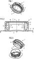
Figure 1 is a perspective view of a lid intended to be applied onto a neck of a container; -
Figure 2 is an enlarged cross-section showing the lid ofFigure 1 , screwed onto a corresponding neck; -
Figure 3 is a perspective view showing the lid and neck ofFigure 2 , when the lid has been removed from the respective container by a user; -
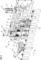
Figure 4 is a perspective view showing an apparatus for applying lids onto corresponding necks of containers; -
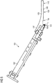
Figure 5 is a side view of a distribution unit for feeding lids to necks of containers; -
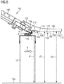
Figures 6 to 9 are side views showing the distribution unit ofFigure 5 in successive steps of the application of a lid to a corresponding container. -
Figure 1 shows alid 1 intended to be applied onto a container neck. Thelid 1 comprises anend wall 2, which may be shaped as a disk, particularly a circular disk. Thelid 1 further comprises aside wall 3, which may be substantially cylindrical, appended to theend wall 2. - The
side wall 3 extends around an axis of thelid 1, whereas theend wall 2 extends transversely, in particular perpendicularly, to the axis of thelid 1. - The
side wall 3 is provided with one or more internal threads 4 capable of engaging with corresponding threads obtained on the container neck. Theside wall 3 may be externally provided with a plurality ofknurls 5, which allow a user to more easily grip thelid 1. - Two
appendages 6 project from an outer surface of theside wall 3, at diametrically opposite positions. - A
welding promoting element 7, which may be for example disk-shaped, is anchored to an inner surface of theend wall 2, i.e. to a surface that, in use, faces the container neck. - The
lid 1 may comprise anannular rib 8, obtained integrally with theend wall 2, which axially protrudes from theend wall 2 towards the inside of thelid 1. Theannular rib 8 defines a seat for receiving thewelding promoting element 7. - The
welding promoting element 7 is defined by a multilayer sheet element distinct from theend wall 2 and permanently connected to the latter. In particular, thewelding promoting element 7 comprises a layer of conductive material, e.g. an aluminium foil, and at least two layers of heat-sealable plastic material, e.g. polyethylene films, covering both sides of the layer of conductive material and defining respective opposite faces of thewelding promoting element 7. A face of thewelding promoting element 7 is welded to theend wall 2 by the heat generated when inducing a current in the layer made of conductive material. - As shown in
Figure 2 , thelid 1 is intended to be applied onto aneck 9 of acontainer 10, particularly a sealed container for packaging pourable food products. - The container can be made of a packaging material having a multilayer structure, as disclosed in the introductory part of this patent application.
- The
neck 9 is included in an opening device comprising a pouringspout 11 fixed to the packaging material forming thecontainer 10. Theneck 9 has a substantially cylindrical tubular shape and extends around an axis A. Theneck 9 defines a pouringopening 12, through which the content of thecontainer 10 can be poured by a user. On an outer surface of theneck 9, extending around the axis A, one or moreouter threads 13 are provided, which are capable of engaging with the inner threads 4 of thelid 1. Thus, thelid 1 can be removably coupled to theneck 9. When thelid 1 is screwed onto theneck 9, the axis of thelid 1 is coincident with the axis A of theneck 9. - The pouring
opening 12 is initially closed by aclosing element 14 that is integrally connected to the pouringspout 11 at atear line 15, along which theclosing element 14 can be detached from the pouringspout 11. - The pouring
spout 11 and theclosing element 14 are formed in one piece on a receivingportion 16 of the packaging material forming thecontainer 10, whilst thelid 1 is formed separately from the pouringspout 11 and theclosing element 14, and then fitted thereto. The pouringspout 11 and theclosing element 14 may be obtained by moulding molten plastic material - in particular by an injection moulding operation - on the packaging material before it is transformed into acontainer 10. - The receiving
portion 16 may be defined by a so called pre-laminated hole made in the packaging material forming thecontainer 10, i.e. a hole made through a base layer of the packaging material and covered by one, two, or more lamination layers of the packaging material, which seal the hole. In an alternative embodiment, the receivingportion 16 may be simply defined by a hole made through the whole thickness of the packaging material forming thecontainer 1, which is intended to be sealed by the pouringspout 11 and theclosing element 14. In another embodiment, the receivingportion 16 may be defined by a patch fixed to the rest of packaging material to seal a hole formed, in this case, through the whole thickness of the packaging material. - The closing
element 14 is formed in one piece with a protrudingportion 17 extending through the pouringopening 12. The protrudingportion 17 is intended to be welded to thewelding promoting element 7, after thelid 1 has been screwed onto theneck 9. - The protruding
portion 17 may comprise anannular body 18 for contacting thewelding promoting element 7, and two ormore legs 19 for connecting theannular body 18 to theclosing element 14. In the example shown, thelegs 19 are diametrically opposite one another. - The
container 10 is formed, filled and sealed in a filling machine and is already provided with the pouringspout 11, the closingelement 14 and the protrudingportion 17 when leaving the filling machine. Thereafter, as will be described in greater detail hereinbelow, an applying head screws alid 1 onto theneck 9. Thewelding promoting element 7 of thelid 1 is then welded to the protrudingportion 17, by inducing an electric current in the conductive layer of thewelding promoting element 7. This current melts the heat-sealable layer of thewelding promoting element 7 that faces theneck 9, thereby permanently joining thewelding promoting element 7 to the protrudingportion 17. - In use, the first opening of the
container 10 is obtained by rotating thelid 1 relative to the pouringspout 11 around the axis A. At the beginning of the rotation impressed by the user on thelid 1, thelegs 19 bend in the direction of rotation, thereby exerting a pulling action on theclosing element 14 at a given point of thetear line 15. In other words, due to thelegs 19, the torque exerted on thelid 1 is transformed in a pulling action on theclosing element 14, which starts to detach from the pouringspout 11 at two given points along thetear line 15. - By continuing to rotate the
lid 1, the latter unscrews completely from the pouringspout 11. As shown inFigure 3 , the closingelement 14 is fully detached from the pouringspout 11 along thetear line 15, and remains attached to thelid 1. At this point, the user can pour the content of thecontainer 10 through the pouringopening 12. - The user can then use the
lid 1 to again close or open thecontainer 10, by screwing thelid 1 onto theneck 9 or, respectively, unscrewing thelid 1 from theneck 9, as often as desired. -
Figure 4 shows an applying unit orapparatus 20 for applyinglids 1 ontorespective containers 10, which have already been formed, filled and sealed in a filling machine provided upstream of theapparatus 20. - Each
container 10 has, in the embodiment shown, a substantially parallelepiped body and a slanted top wall, i.e. a top wall that is inclined with respect to a base wall of thecontainer 10. In other words, when the base wall of thecontainer 10 rests on a horizontal surface, the top wall is inclined with respect to a horizontal plane parallel to the base wall. - In another embodiment, not shown, each
container 10 has a substantially parallelepiped body and a top wall substantially parallel to the base wall. - In general, the
apparatus 20 may work withcontainers 10 having different shapes and/or dimensions. - The
apparatus 20 comprises a conveying device 100 (shown inFigures 6 to 9 ) for advancing thecontainers 10 in an advancement direction F, particularly along a rectilinear path. The conveyingdevice 100 comprises a linear conveyor, for example a belt conveyor or a roller conveyor. The conveyingdevice 100 is configured to advance thecontainers 10 continuously along the advancement direction F. - Upstream of the conveying
device 100, a sequencing device may be provided, in order to arrange thecontainers 10 at a preset distance one from another, i.e. in a sequence having a preset pitch. It is thus ensured that thecontainers 10 are regularly spaced when entering theapparatus 20. - The
apparatus 20 further comprises adistribution unit 101 for feeding thelids 1 to thenecks 9 of thecontainers 10 advancing along the advancement direction F. - The
distribution unit 101 comprises achute element 102 arranged for receiving a row of lids. - The distribution unit further comprises a feeding unit, which is not shown, for supplying the
lids 1 to thechute element 102. - The
chute element 102 is inclined with respect to the conveyingdevice 100, so that the distance between thechute element 102 and the conveyingdevice 100 decreases when moving along the advancement direction F. - The
chute element 102 has anoutlet opening 103 arranged for releasing the lids one at a time. - At the
outlet opening 103, thechute element 102 has a couple offlexible retaining element 104 that loosely retains onelid 1, i.e. the first lid of the above-mentioned row. - The
distribution unit 101 is positioned above the conveyingdevice 100 so that eachcontainer 10 being advanced by the conveyingdevice 100 interacts with thechute element 102 to remove acorresponding lid 1 from theoutlet opening 103. - The
distribution unit 101 further comprises aguide element 105. - The
guide element 105 comprises afastening portion 107 connected to thechute element 102 by means of connecting elements, for example nuts. - The
guide element 105 comprises anactive surface 106 extending on the opposite side of thechute element 102 with respect to theoutlet opening 103 and arranged for interacting with thelids 1. - The
active surface 106 faces towards the conveyingdevice 100, i.e. towards thenecks 9 on which thelids 2 have to be applied. - The
active surface 106 has a stepped profile. - The
active surface 106 comprises a firstactive portion 108 arranged downstream of the outlet opening 103 with respect to the advancement direction F. The firstactive portion 108 extends immediately downstream of theoutlet opening 103. - The first
active portion 108 is so shaped as to guide thelid 1 during removal from theoutlet opening 103 and place thelid 1 in a plane substantially parallel to the top wall of thecontainer 10, i.e. substantially parallel to the plane defined by anupper edge 111 of theneck 9. - The first
active portion 108 defines with aside surface 112 of the guide element 105 a drivingelement 116 that interacts with theend wall 2 of thelid 1 when thelid 1 is retained by theflexible retaining elements 104 and when thelid 1 is removed from theoutlet opening 103. - The first
active portion 108 comprises a firstplanar face 113 that places thelid 1 in the above-mentioned plane substantially parallel to the top wall of thecontainer 10 and keeps thelid 1 in position when thecontainer 10 that has received thelid 1 is advanced by the conveyingdevice 101. - The
active surface 106 comprises a secondactive portion 109 arranged downstream of the firstactive portion 108 with respect to the advancement direction F. In other words, the secondactive portion 109 is arranged on the opposite side of the firstactive portion 108 with respect to theoutlet opening 103. - The second
active portion 109 is so shaped as to press thelid 1 on theneck 9 in order to correctly position thelid 1 with respect to theneck 9. - When the second
active portion 109 presses thelid 1 on theneck 9, the top panel of thecontainer 10 may be slightly elastically deformed, i.e. it may pass from a substantially planar configuration to a curved configuration. - The second
active portion 109 comprises a secondplanar face 114 that causes a preliminary engagement, i.e. before the screwing operation, of thelid 1 on theneck 9, so as to avoid that thelid 1 is tilted with respect to theneck 9 and therefore the subsequent screwing operation is made difficult, or even impossible. - The
active surface 106 comprises a thirdactive portion 110 arranged downstream of the secondactive portion 109 with respect to the advancement direction F. In other words, the thirdactive portion 110 is arranged on the opposite side of the secondactive portion 109 with respect to the firstactive portion 108. - The second
active portion 109 is interposed between the firstactive portion 108 and the thirdactive portion 110. - The third
active portion 110 is so shaped as to allow releasing the pressure generated by the secondactive portion 109 on thelid 1, and therefore on thecontainer 10. - The third
active portion 110 comprises a thirdplanar face 115 that prevents thelid 1 from being expelled from theneck 9 once the secondactive portion 109 does not pushes thelid 1 on theneck 9 anymore and therefore the top panel of thecontainer 10 moves back from the curved configuration to the substantially planar configuration. - The first
active portion 108 is placed at a first distance d1 from the conveyingdevice 100. - The second
active portion 109 is placed at a second distance d2 from the conveyingdevice 100. - The third
active portion 110 is placed at a third distance d3 from the conveyingdevice 100. - The first distance d1 is greater than the second distance d2.
- The third distance d3 is greater than the second distance d2.
- The first distance d1 may be different from the third distance d3.
- The
guide element 105 further comprises a first connectingportion 117 connecting the firstplanar face 113 and the secondplanar face 114. - The first connecting
portion 117 has a slanted, or curved, configuration. - The distance of the first connecting
portion 117 from the conveyingdevice 100 decreases when moving from the firstplanar face 113 to the secondplanar face 114, i.e. along the advancement direction F. - The
guide element 105 further comprises a second connectingportion 118 connecting the secondplanar face 114 and the thirdplanar face 115. - The second connecting
portion 118 has a slanted, or curved, configuration. - The distance of the second connecting
portion 118 from the conveyingdevice 100 increases when moving from the secondplanar face 114 to the thirdplanar face 115, i.e. along the advancement direction F. - During operation, as shown in
Figure 6 , when acontainer 10, advanced along the advancement direction F, reaches thechute element 102, theneck 9 of thecontainer 10 interacts with thelid 1 retained by the outlet opening 103 of thedistribution unit 101 and removes thelid 1 from thedistribution unit 102. In other words, thelid 1 is stripped from the outlet opening 103 located downstream of thechute element 102 by theneck 9 of anunderlying container 10. - As shown in
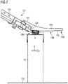
Figure 7 , the firstactive portion 108 guides thelid 1 during removal from theoutlet opening 103 and places thelid 1 in a plane substantially parallel to the top wall of thecontainer 10, i.e. substantially parallel to the plane defined by theupper edge 111 of theneck 9. - As shown in
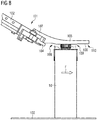
Figure 8 , the secondactive portion 109 presses thelid 1 on theneck 9 in order to cause a preliminary engagement of thelid 1 on the neck. In particular, the secondactive portion 109 correctly positions thelid 1 with respect to theneck 9 and avoids that thelid 1, once placed on theneck 9, is tilted with respect to theneck 9. - The second active portion 109 - when pressing the
lid 1 on the neck 9 - slightly deforms the top panel of thecontainer 10, which passes from a substantially planar configuration to a curved configuration. - As shown in
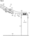
Figure 9 , the third active portion 110 - being placed further away from the conveyingdevice 100 than the second active portion 109 - allows the top panel of thecontainer 10 to move back from the curved configuration to the substantially planar configuration and, at the same time, prevents thelid 1 from being expelled from theneck 9 when the deformation due to the pressure exerted by the secondactive portion 109 is released. - Subsequently, the
lid 2 is screwed on theneck 9, as will be better explained in the following. - The
apparatus 20 further comprises a group of applyingheads 23 for applying thelids 1 to therespective containers 10, particularly by screwing eachlid 1 onto acorresponding neck 9 of acontainer 10. - In the embodiment shown, the group of applying heads comprises two applying
heads 23, arranged in sequence along the advancement direction F. However, the group of applying heads may comprise also a number of applyingheads 23 different from two, for example three, four or more applyingheads 23. Each applyinghead 23 is arranged to screw alid 1 onto acorresponding neck 9. - The applying heads 23 are supported by a
common support element 24. Thesupport element 24 may be formed in one piece, or may be assembled from a plurality of components that are connected to one another so as to behave, in use, like a single piece. - In the example shown, the
support element 24 is shaped as a back plate from which a plurality of projecting walls extend, so as to define a plurality ofrecesses 25, in each of which an applyinghead 23 is partially housed. Thesupport element 24 may nevertheless have shapes different from that shown in the drawings. - The applying heads 23 are fitted to the
support element 24 so that the distance between two consecutive applyingheads 23 is equal to the distance between twoconsecutive containers 10 advanced along the advancement direction F, i.e. to the pitch of thecontainers 10. - A
movement device 26 is provided for moving the group of applyingheads 23 along the advancement direction F, so that each applyinghead 23 is coupled to anunderlying container 10 for a portion of the path thereof along the advancement direction F. In other words, themovement device 26 allows the applyingheads 23 to follow thecontainers 10 with which they interact along a portion of the path of thecontainers 10. The applying heads 23 are hence movable synchronously with the conveyingdevice 100 that advances thecontainers 10 in the advancement direction F, along the above mentioned portion of the path of the conveyingdevice 100. - The
movement device 26 may comprise amotor 27, possibly connected to agear box 28, arranged for driving apulley 30 around which abelt 29 is wound. Thebelt 29 is further wound around a drivenpulley 31. Thebelt 29 has an active branch that is intended to drive thesupport element 24 and runs parallelly to the advancement direction F. - A pair of guiding
bars 32, each of which extends parallelly to the advancement direction F, is provided for guiding thesupport element 24 as the latter moves along the advancement direction F. In particular, a sliding element that is not shown is slidable along the guiding bars 32. Thesupport element 24 is fixed relative to the sliding element. - One or more connecting plates, which are not shown, are fastened to the
belt 29. The connecting plates are fixed relative to the sliding element mentioned above. - The
motor 27 is configured for rotating thepulley 30 in two opposite rotation directions, so that thebelt 29 may be driven forwards or backwards parallelly to the advancement direction F. - When the active branch of the
belt 29 moves parallelly to the advancement direction F, the support element 24 - which, as explained above, is fixed relative to the belt 29 - moves together with thebelt 29. The applying heads 23, which are supported by thesupport element 24, are therefore moved forwards or backwards along the advancement direction F. In particular, when the applyingheads 23 are moved forwards along the advancement direction F, the applyingheads 23 can followrespective containers 10 so that each applyinghead 23 applies alid 1 on thecorresponding neck 9. After disengaging fromrespective containers 10, the applyingheads 23 can be moved backwards along the advancement direction F so as to be brought back to a starting point at which the applyingheads 23 can start to interact withnew containers 10. - The
movement device 26 thus moves synchronously the applyingheads 23, which means that the applyingheads 23 are moved together along the advancement direction F by themovement device 26. In other words, the applyingheads 23 are moved by themovement device 26 simultaneously and by the same extent, along the advancement direction F. - In an embodiment that is not shown, the
movement device 26 may comprise a toothed rack fixed relative to thesupport element 24. Themotor 27 has a shaft coupled to a toothed wheel or pinion that engages with the toothed rack, so as to move the latter forwards or backwards parallelly to the advancement direction F. - More in general, the
movement device 26 may comprise any transmission device that is capable of transforming rotation of a shaft of themotor 27 into a linear motion of a linearly movable element fixed relative to thesupport element 24. - Each applying
head 23 comprises a pair ofgripping elements 33 intended to interact with thelid 1 for screwing it onto theneck 9. Thegripping elements 33 of an applyinghead 23 are supported by a supportingcomponent 35 connected to astem 36. Each applyinghead 23 further comprises a drivingdevice 34 for driving thegripping elements 33. The driving device is fastened to thesupport element 24. The drivingdevice 34 is directly connected to thestem 36, so as to move the supportingcomponent 35 and hence drive simultaneously both thegripping elements 33. - In particular, the driving
device 34 is capable of causing thestem 36 to slide parallelly to the longitudinal axis thereof, thereby displacing the supportingcomponent 35 and hence thegripping elements 33 in a direction parallel to the axis A of aneck 9. Thegripping elements 33 can thus be moved towards alid 1 to be screwed, or alternatively be moved away from alid 1 that has already been screwed onto thecorresponding neck 9. To this end, the drivingdevice 34 may comprise a linear motor. - The driving
device 34 is furthermore configured to rotate thestem 36, and hence the supportingcomponent 35 and thegripping elements 33, around a longitudinal axis of thestem 36 that, in use, coincides with the axis A of aneck 9. - By rotating the supporting
component 35 around the longitudinal axis of thestem 36, while the latter is moved towards thecontainer 1, thegripping elements 33 move along a helix, thereby screwing thelid 1 onto theneck 9, as will be described in greater detail hereinbelow. - In an embodiment that is not shown, the applying
heads 23 may be configured to apply, onto thecontainers 10,lids 1 that do not comprise theappendages 6, i.e. lids 1 that are delimited by acylindrical side wall 3. - The
apparatus 20 further comprises a plurality of welding heads 43 for induction welding thelid 1 to the protrudingportion 17 that projects from the closingelement 14. In particular, each weldinghead 43 is configured to generate in the conductive layer of thewelding promoting element 7 an electric current, which melts the heat-sealable layer of thewelding promoting element 7 facing the closingelement 14. This heat-sealable layer thus adheres to the protrudingportion 17, which consequently becomes permanently attached to thelid 1. - The welding heads 43 are arranged downstream of the applying
heads 23, along the conveyingdevice 100 that advances thecontainers 10 in the advancement direction F. The welding heads 43 thus interact with thecontainers 10 after the applyingheads 23 have screwed thelids 1 onto thecontainers 10. - The number of welding heads 43 may be equal to the number of applying
heads 23. In the example shown, two welding heads 43 are provided, but this condition is not essential and the number of welding heads 43 could also be different from two. - The distance between two consecutive welding heads 43 is equal to the distance between two
consecutive containers 10 advancing along the advancement direction F. Similarly, the distance between the last applyinghead 23 and thefirst welding head 43 is equal to the distance between twoconsecutive containers 10. - The welding heads 43 are movable forwards and backwards in the advancement direction F, i.e. are movable synchronously with the conveying
device 100 that advances thecontainers 10 in the advancement direction F, along a part of the path of the conveyingdevice 100. Thus, each weldinghead 43 is capable of following acontainer 10 in order to interact with thecorresponding lid 1 for a time sufficient to ensure welding of thelid 1 to the protrudingportion 17. When thelid 1 has been welded to the protrudingportion 17, thewelding head 43 moves backwards so as to reach an initial position in which it is ready to weld anew lid 1 to the correspondingcontainer 10. - All the welding heads 43 can be moved synchronously by a common mechanism. To this end, all the welding heads 43 can be supported by a
common support member 44 so that, by moving thesupport member 44 in the advancement direction F, all the welding heads 43 are moved together in the advancing direction F forwards or backwards. - In the example shown, the welding heads 43 are moved by the
same movement device 26 that also displaces the applyingheads 23. Thesupport member 44 is fixed relative to thesupport element 24, for example because thesupport member 44 is directly fastened to thesupport element 24. Thus, when themotor 27 moves thesupport element 24 by driving thebelt 29, thesupport member 44, and consequently also the welding heads 43, are also displaced in the advancement direction F. - Each
welding head 43 comprises an electricinduction generating element 51 including a coil that is not shown. By activating the coil, an electric current is induced in the conductive layer of thewelding promoting element 7, with a consequent generation of localized heat causing the heat-sealable layer of thewelding promoting element 7 facing theneck 9 to be welded to the protrudingportion 17. - The
welding head 43 comprises anactuator device 52 for displacing the electricinduction generating element 51 in a displacement direction arranged transversely, in particular perpendicularly, to the advancement direction F, so as to move the electricinduction generating element 51 towards alid 1 or alternatively away from alid 1. More precisely, theactuator device 52 is intended to move the electricinduction generating element 51 parallelly to the axis of thelid 1 that is being welded. - The
actuator device 52 may comprise for example an electric linear motor or a pneumatic actuator. - The above description mainly refers to
lids 1 that are intended to be welded to corresponding protrudingportions 17 of theclosing elements 14. The resultingcontainers 10 can be opened in a single step, because by unscrewing thelid 1, the closingelement 14 is detached from theneck 9. - The
apparatus 20 may nevertheless be used also for applyinglids 1 that do not comprise thewelding promoting element 7. The resultingcontainers 10 will have to be opened in two steps, by first unscrewing thelid 1 and then removing, for example by means of a pull ring, the closingelement 14. In this case, the welding heads 43 are absent, because theapparatus 20 needs simply to screw thelids 1 onto thenecks 9. No welding operations need to be carried out onto thelids 1. - In an alternative embodiment, the
apparatus 20 may be used to apply, onto thenecks 9,lids 1 that are substantially round, i.e. which do not possess theappendages 6. - From the above description it appears that owing to the guide element it is possible to provide a distribution unit that can precisely feed lids to necks of containers, particularly deformable containers made of packaging material having a multilayer structure.
- In particular, the first active portion of the guide element places the lids in a plane substantially parallel to the top wall of the container.
- The second active portion - by slightly deforming the the top panel of the container from a substantially planar configuration to a curved configuration - presses the lid on the neck in order to cause a preliminary engagement of the lid on the neck.
- The third active portion allows the top panel of the container to move back from the curved configuration to the substantially planar configuration and, at the same time, prevents the lid from being expelled from the neck when the deformation due to the pressure exerted by the second active portion is released.
- Clearly, changes may be made to the distribution unit as described and illustrated herein without, however, departing from the scope of the present invention as defined in the accompanying claims.
Claims (9)
- A distribution unit for feeding lids (1) to necks (9) of containers (10), comprising a chute element (102) arranged for receiving a row of lids (1), an outlet opening (103) arranged for releasing said lids (1) one at a time, said outlet opening (103) being positioned above a conveying device (100) suitable for conveying said containers (10) along an advancement direction (F) so that each of said containers (10) interacts with said chute element (102) to remove a corresponding lid (1) from said outlet opening (103), wherein said distribution unit (101) further comprises a guide element (105) having an active surface (106) extending on an opposite side of said chute element (102) with respect to said outlet opening (103) and arranged for interacting with said lids (1), said active surface (106) having a stepped profile, wherein said active surface (106) comprises a first active portion (108) extending from said outlet opening (103), wherein said active surface (106) comprises a second active portion (109) arranged on an opposite side of said first active portion (108) with respect to said outlet opening (103), characterized in that said active surface (106) comprises a third active portion (110) arranged on an opposite side of said second active portion (109) with respect to said first active portion (108), said first active portion (108) is arranged downstream of said outlet opening (103) with respect to said advancement
direction (F), said second active portion (109) is arranged downstream of said first active portion (108) with respect to said advancement direction (F) and said third active portion (110) is arranged downstream of said second active portion (109) with respect to said advancement direction (F), and said first active portion (108) is placed at a first distance (d1) from said conveying device (100), said second active portion (109) is placed at a second distance (d2) from said conveying device (100) and said third active portion (110) is placed at a third distance (d3) from said conveying device (100), said first distance (d1) being greater than said second distance (d2) and said third distance (d3) being greater than said second distance (d2). - A distribution unit according to claim 1, wherein said guide element (105) comprises a fastening portion (107) connected to said chute element (102) by means of connecting elements.
- A distribution unit according to claim 1, or 2, wherein said first active portion (108) comprises a first planar face (113).
- A distribution unit according to any one of the preceding claims, wherein said second active portion (109) comprises a second planar face (114).
- A distribution unit according to any one of the preceding claims, wherein said third active portion (110) comprises a third planar face (115).
- A distribution unit according to any one of the preceding claims, wherein said second active portion (109) is interposed between said first active portion (108) and said third active portion (110) .
- A distribution unit according to any one of the preceding claims, wherein said guide element (105) further comprises a first connecting portion (117) connecting said first active portion (108) and said second active portion (109) and a second connecting portion (118) connecting said second active portion (109) and said third active portion (110).
- A distribution unit according to claim 7, wherein said first connecting portion (117) and said second connecting portion (118) have a slanted, or curved, configuration.
- A distribution unit according to any one of the preceding claims, wherein said chute element (102) is inclined with respect to said conveying device (100), so that the distance between said chute element (102) and said conveying device (100) decreases when moving along said advancement direction (F) .
Priority Applications (5)
| Application Number | Priority Date | Filing Date | Title |
|---|---|---|---|
| EP16155511.5A EP3205589B1 (en) | 2016-02-12 | 2016-02-12 | A distribution unit for feeding lids to necks of containers |
| CN201780004130.4A CN108290655B (en) | 2016-02-12 | 2017-02-02 | Dispensing unit for feeding caps to the neck of a container |
| US15/776,271 US11186392B2 (en) | 2016-02-12 | 2017-02-02 | Distribution unit for feeding lids to necks of containers |
| PCT/EP2017/052286 WO2017137308A1 (en) | 2016-02-12 | 2017-02-02 | A distribution unit for feeding lids to necks of containers |
| JP2018542243A JP6758789B2 (en) | 2016-02-12 | 2017-02-02 | Distribution unit that supplies the lid to the neck of the container |
Applications Claiming Priority (1)
| Application Number | Priority Date | Filing Date | Title |
|---|---|---|---|
| EP16155511.5A EP3205589B1 (en) | 2016-02-12 | 2016-02-12 | A distribution unit for feeding lids to necks of containers |
Publications (2)
| Publication Number | Publication Date |
|---|---|
| EP3205589A1 EP3205589A1 (en) | 2017-08-16 |
| EP3205589B1 true EP3205589B1 (en) | 2019-04-03 |
Family
ID=55361372
Family Applications (1)
| Application Number | Title | Priority Date | Filing Date |
|---|---|---|---|
| EP16155511.5A Active EP3205589B1 (en) | 2016-02-12 | 2016-02-12 | A distribution unit for feeding lids to necks of containers |
Country Status (5)
| Country | Link |
|---|---|
| US (1) | US11186392B2 (en) |
| EP (1) | EP3205589B1 (en) |
| JP (1) | JP6758789B2 (en) |
| CN (1) | CN108290655B (en) |
| WO (1) | WO2017137308A1 (en) |
Families Citing this family (2)
| Publication number | Priority date | Publication date | Assignee | Title |
|---|---|---|---|---|
| JP2021011298A (en) * | 2019-07-08 | 2021-02-04 | 株式会社細川洋行 | Structure of mouth plug part, package, and closing method of package |
| CN112875611A (en) * | 2021-01-08 | 2021-06-01 | 成都易佰联自动化设备有限公司 | Automatic in-line type cap screwing machine with good cap screwing effect |
Family Cites Families (62)
| Publication number | Priority date | Publication date | Assignee | Title |
|---|---|---|---|---|
| US1835335A (en) * | 1929-04-10 | 1931-12-08 | U S Bottlers Machinery Co | Bottle capping machine |
| US2053763A (en) * | 1932-10-14 | 1936-09-08 | Standard Cap & Seal Corp | Cap feeding device |
| US2132335A (en) * | 1935-08-09 | 1938-10-04 | White Cap Co | Closure cap applying apparatus |
| US2337032A (en) * | 1940-04-17 | 1943-12-21 | White Cap Co | Cap applying apparatus |
| US2522437A (en) * | 1942-11-14 | 1950-09-12 | Crown Cork & Seal Co | Container sealing apparatus |
| US2386797A (en) * | 1942-12-07 | 1945-10-16 | Owens Illinois Glass Co | Jar capping apparatus |
| US2357826A (en) * | 1942-12-07 | 1944-09-12 | Owens Illinois Glass Co | Capping machine |
| US2435127A (en) * | 1945-05-19 | 1948-01-27 | Boyle Midway Inc | Capping machine |
| US2518856A (en) * | 1946-08-27 | 1950-08-15 | Anchor Hocking Glass Corp | Method and apparatus for sealing containers |
| US2835963A (en) * | 1955-07-07 | 1958-05-27 | Owens Illinois Glass Co | Apparatus for feeding, sorting, and applying ring fitments to containers |
| US2805532A (en) * | 1956-03-19 | 1957-09-10 | Ralph F Anderson | Cover applying apparatus |
| US2931147A (en) * | 1956-07-03 | 1960-04-05 | Owens Illinois Glass Co | Method and apparatus for excluding air in packaging powdered materials |
| US2954900A (en) * | 1956-12-20 | 1960-10-04 | Nat Dairy Prod Corp | Cap feeding apparatus |
| US2972184A (en) * | 1957-11-29 | 1961-02-21 | Andrew & Waitkens Machine Co I | Machine for mounting spouts in the tops of containers |
| US2876605A (en) * | 1958-06-19 | 1959-03-10 | White Cap Co | Machine for applying rotatable closure caps to containers |
| US3012388A (en) * | 1958-10-23 | 1961-12-12 | Anchor Hocking Glass Corp | Means for sealing threaded-type containers |
| US3054234A (en) * | 1960-02-05 | 1962-09-18 | Anchor Hocking Glass Corp | Sealing machine and method |
| US3100957A (en) * | 1960-07-01 | 1963-08-20 | Matthews & Co Jas H | Machine for embossing container lids and placing them on containers |
| US3137982A (en) * | 1961-05-05 | 1964-06-23 | Bopp Decker Plastics Inc | Container capper |
| US3332209A (en) * | 1964-11-27 | 1967-07-25 | David S Knudsen | Lid applicator |
| US3332210A (en) * | 1964-12-02 | 1967-07-25 | Better Plastics Inc | Closure dispenser |
| US3345801A (en) * | 1965-01-04 | 1967-10-10 | Maryland Cup Corp | Auxiliary unit for packaging machine |
| US3438174A (en) * | 1965-02-11 | 1969-04-15 | Anchor Hocking Glass Corp | Container sealing machine |
| GB1061705A (en) * | 1965-05-05 | 1967-03-15 | Metal Box Co Ltd | Improvements in or relating to apparatus for feeding caps to containers |
| US3380225A (en) * | 1965-10-12 | 1968-04-30 | Anchor Hocking Glass Corp | Cap applicator |
| US3460314A (en) * | 1966-10-17 | 1969-08-12 | Anderson Bros Mfg Co | Lid dispensing apparatus |
| US3533216A (en) * | 1968-09-26 | 1970-10-13 | Filler Machine Co Inc The | Mechanism for feeding and applying circular caps to containers |
| US3656605A (en) * | 1970-06-05 | 1972-04-18 | Larry C Gess | Apparatus for orienting and feeding caps |
| CH560627A5 (en) * | 1971-01-28 | 1975-04-15 | Remy & Cie E P | |
| SE361162B (en) * | 1972-01-24 | 1973-10-22 | E Zetterberg | |
| US3800501A (en) * | 1972-02-03 | 1974-04-02 | Continental Can Co | Cap feeding apparatus |
| US3908341A (en) * | 1974-02-07 | 1975-09-30 | Dairy Cap Corp | Cap feeding device |
| US3924384A (en) * | 1975-01-30 | 1975-12-09 | Phillips Petroleum Co | Method and apparatus for capping containers |
| US3977161A (en) * | 1975-07-28 | 1976-08-31 | Anchor Hocking Corporation | Closure cap feed chute with automatic cap stop |
| US4077188A (en) * | 1977-03-07 | 1978-03-07 | Anderson Bros. Mfg. Co. | Apparatus for applying covers to containers |
| US4199914A (en) * | 1978-09-08 | 1980-04-29 | Anchor Hocking Corporation | Sealing machine closure cap pickup |
| US4279115A (en) * | 1979-03-12 | 1981-07-21 | Anchor Hocking Corporation | High speed straight line container sealing machine |
| US4246738A (en) * | 1979-06-18 | 1981-01-27 | Shibuya Kogyo Company, Ltd. | Air chuck for capping or uncapping machine |
| GB2125379B (en) * | 1982-08-17 | 1986-06-18 | Metal Box Plc | Capping machines |
| US4601160A (en) * | 1985-03-08 | 1986-07-22 | Heisler Raymond A | Cover separating, feeding, placing and metering apparatus |
| US4932824A (en) * | 1989-01-06 | 1990-06-12 | Pneumatic Scale Corporation | Cap feeder |
| US5012630A (en) * | 1990-03-01 | 1991-05-07 | Owens-Illinois Closure Inc. | Closure application system |
| US5426912A (en) * | 1990-10-31 | 1995-06-27 | Continental White Cap, Inc. | Magnetic cap guide |
| US5398480A (en) * | 1994-06-27 | 1995-03-21 | New England Machinery, Inc. | Device for stabilizing caps while being attached to containers |
| GB9504778D0 (en) * | 1995-03-09 | 1995-04-26 | Metal Box Plc | "Capping apparatus" |
| CA2216240C (en) * | 1996-10-15 | 2001-04-24 | Jeffrey E. Gunderson | Lid dispenser with dial adjustment and pivoting access door |
| IT1296516B1 (en) * | 1997-06-30 | 1999-07-02 | Donatella Pedrotti | EQUIPMENT FOR THE SEQUENTIAL APPLICATION OF PLASTIC LIDS TO GROUPS OF CANS OR JARS. |
| US7040075B2 (en) * | 2001-08-08 | 2006-05-09 | The Clorox Company | Nitrogen cap chute end |
| JP2004359286A (en) * | 2003-06-04 | 2004-12-24 | Toho Kogyo Kk | Lid member fitting device |
| US20070056251A1 (en) * | 2005-01-05 | 2007-03-15 | Ruppman Kurt H Sr | Method and Apparatus for Flushing a Container with an Inert Gas |
| US7412811B2 (en) * | 2005-04-15 | 2008-08-19 | Packaging Technologies, Inc. | Multiflow gassing system |
| DE102007023400A1 (en) * | 2006-12-12 | 2008-06-19 | Robert Bosch Gmbh | Tactical machine for filling containers |
| DE602007005462D1 (en) * | 2007-06-15 | 2010-05-06 | Tetra Laval Holdings & Finance | Separating unit for separating individually attachable to corresponding packaging for flowable food opening devices |
| DE102008035605B4 (en) * | 2008-07-31 | 2012-06-14 | Khs Gmbh | Transport line for conveying caps or similar closures for closing bottles or similar containers |
| FR2947811B1 (en) * | 2009-07-07 | 2015-07-24 | Sidel Participations | GUIDING CORRIDOR FOR CLOSURE ARTICLES |
| DE202013007124U1 (en) * | 2013-08-08 | 2013-09-18 | Beko-Trucks Gmbh | Variable, self-locking lashing system |
| DE202013007104U1 (en) * | 2013-08-09 | 2013-09-24 | Dietz & Rollwa Automation Gmbh | Device for automatic feeding and / or sorting systems for guiding, conveying and / or positioning of container closures, in particular of container closures for tubes, cream jars or bottles |
| US20150107197A1 (en) * | 2013-10-23 | 2015-04-23 | Tyson Foods, Inc. | System and method for installing a lid |
| EP2927132B1 (en) * | 2014-04-04 | 2016-09-14 | Tetra Laval Holdings & Finance S.A. | Unit for the application of lids of opening devices |
| DK3153414T3 (en) * | 2015-10-05 | 2018-06-25 | Tetra Laval Holdings & Finance | APPLICATION UNIT TO APPLY A COVER TO A CONTAINER |
| DK3153415T3 (en) * | 2015-10-05 | 2019-01-21 | Tetra Laval Holdings & Finance | DEVICE TO CLOSE A CONTAINER |
| DK3153413T3 (en) * | 2015-10-05 | 2019-01-21 | Tetra Laval Holdings & Finance | PROCEDURE AND MOUNTING MECHANISM, INCLUDING A MOUNTING HEAD FOR, MOUNTING A COVER TO A CONTAINER |
-
2016
- 2016-02-12 EP EP16155511.5A patent/EP3205589B1/en active Active
-
2017
- 2017-02-02 WO PCT/EP2017/052286 patent/WO2017137308A1/en active Application Filing
- 2017-02-02 JP JP2018542243A patent/JP6758789B2/en active Active
- 2017-02-02 CN CN201780004130.4A patent/CN108290655B/en active Active
- 2017-02-02 US US15/776,271 patent/US11186392B2/en active Active
Non-Patent Citations (1)
| Title |
|---|
| None * |
Also Published As
| Publication number | Publication date |
|---|---|
| WO2017137308A1 (en) | 2017-08-17 |
| US11186392B2 (en) | 2021-11-30 |
| JP2019506340A (en) | 2019-03-07 |
| JP6758789B2 (en) | 2020-09-23 |
| CN108290655B (en) | 2021-12-07 |
| EP3205589A1 (en) | 2017-08-16 |
| CN108290655A (en) | 2018-07-17 |
| US20200255171A1 (en) | 2020-08-13 |
Similar Documents
| Publication | Publication Date | Title |
|---|---|---|
| EP3456521B1 (en) | A welding head | |
| US10815017B2 (en) | Apparatus for capping a container | |
| EP3153414B1 (en) | An applying unit for applying a lid onto a container | |
| CN107921715B (en) | Welding head | |
| US10967996B2 (en) | Method of, and an applying head for, applying a lid onto a container | |
| US11186392B2 (en) | Distribution unit for feeding lids to necks of containers | |
| JP2018531164A6 (en) | Welding head |
Legal Events
| Date | Code | Title | Description |
|---|---|---|---|
| PUAI | Public reference made under article 153(3) epc to a published international application that has entered the european phase |
Free format text: ORIGINAL CODE: 0009012 |
|
| STAA | Information on the status of an ep patent application or granted ep patent |
Free format text: STATUS: THE APPLICATION HAS BEEN PUBLISHED |
|
| AK | Designated contracting states |
Kind code of ref document: A1 Designated state(s): AL AT BE BG CH CY CZ DE DK EE ES FI FR GB GR HR HU IE IS IT LI LT LU LV MC MK MT NL NO PL PT RO RS SE SI SK SM TR |
|
| AX | Request for extension of the european patent |
Extension state: BA ME |
|
| STAA | Information on the status of an ep patent application or granted ep patent |
Free format text: STATUS: REQUEST FOR EXAMINATION WAS MADE |
|
| 17P | Request for examination filed |
Effective date: 20180216 |
|
| RBV | Designated contracting states (corrected) |
Designated state(s): AL AT BE BG CH CY CZ DE DK EE ES FI FR GB GR HR HU IE IS IT LI LT LU LV MC MK MT NL NO PL PT RO RS SE SI SK SM TR |
|
| GRAP | Despatch of communication of intention to grant a patent |
Free format text: ORIGINAL CODE: EPIDOSNIGR1 |
|
| STAA | Information on the status of an ep patent application or granted ep patent |
Free format text: STATUS: GRANT OF PATENT IS INTENDED |
|
| INTG | Intention to grant announced |
Effective date: 20180824 |
|
| GRAJ | Information related to disapproval of communication of intention to grant by the applicant or resumption of examination proceedings by the epo deleted |
Free format text: ORIGINAL CODE: EPIDOSDIGR1 |
|
| STAA | Information on the status of an ep patent application or granted ep patent |
Free format text: STATUS: REQUEST FOR EXAMINATION WAS MADE |
|
| GRAP | Despatch of communication of intention to grant a patent |
Free format text: ORIGINAL CODE: EPIDOSNIGR1 |
|
| STAA | Information on the status of an ep patent application or granted ep patent |
Free format text: STATUS: GRANT OF PATENT IS INTENDED |
|
| INTC | Intention to grant announced (deleted) | ||
| INTG | Intention to grant announced |
Effective date: 20181205 |
|
| GRAS | Grant fee paid |
Free format text: ORIGINAL CODE: EPIDOSNIGR3 |
|
| GRAA | (expected) grant |
Free format text: ORIGINAL CODE: 0009210 |
|
| STAA | Information on the status of an ep patent application or granted ep patent |
Free format text: STATUS: THE PATENT HAS BEEN GRANTED |
|
| AK | Designated contracting states |
Kind code of ref document: B1 Designated state(s): AL AT BE BG CH CY CZ DE DK EE ES FI FR GB GR HR HU IE IS IT LI LT LU LV MC MK MT NL NO PL PT RO RS SE SI SK SM TR |
|
| REG | Reference to a national code |
Ref country code: GB Ref legal event code: FG4D |
|
| REG | Reference to a national code |
Ref country code: CH Ref legal event code: EP Ref country code: AT Ref legal event code: REF Ref document number: 1115442 Country of ref document: AT Kind code of ref document: T Effective date: 20190415 |
|
| REG | Reference to a national code |
Ref country code: DE Ref legal event code: R096 Ref document number: 602016011737 Country of ref document: DE |
|
| REG | Reference to a national code |
Ref country code: IE Ref legal event code: FG4D |
|
| REG | Reference to a national code |
Ref country code: NL Ref legal event code: MP Effective date: 20190403 |
|
| REG | Reference to a national code |
Ref country code: LT Ref legal event code: MG4D |
|
| REG | Reference to a national code |
Ref country code: AT Ref legal event code: MK05 Ref document number: 1115442 Country of ref document: AT Kind code of ref document: T Effective date: 20190403 |
|
| PG25 | Lapsed in a contracting state [announced via postgrant information from national office to epo] |
Ref country code: NL Free format text: LAPSE BECAUSE OF FAILURE TO SUBMIT A TRANSLATION OF THE DESCRIPTION OR TO PAY THE FEE WITHIN THE PRESCRIBED TIME-LIMIT Effective date: 20190403 |
|
| PG25 | Lapsed in a contracting state [announced via postgrant information from national office to epo] |
Ref country code: CZ Free format text: LAPSE BECAUSE OF FAILURE TO SUBMIT A TRANSLATION OF THE DESCRIPTION OR TO PAY THE FEE WITHIN THE PRESCRIBED TIME-LIMIT Effective date: 20190403 Ref country code: HR Free format text: LAPSE BECAUSE OF FAILURE TO SUBMIT A TRANSLATION OF THE DESCRIPTION OR TO PAY THE FEE WITHIN THE PRESCRIBED TIME-LIMIT Effective date: 20190403 Ref country code: LT Free format text: LAPSE BECAUSE OF FAILURE TO SUBMIT A TRANSLATION OF THE DESCRIPTION OR TO PAY THE FEE WITHIN THE PRESCRIBED TIME-LIMIT Effective date: 20190403 Ref country code: FI Free format text: LAPSE BECAUSE OF FAILURE TO SUBMIT A TRANSLATION OF THE DESCRIPTION OR TO PAY THE FEE WITHIN THE PRESCRIBED TIME-LIMIT Effective date: 20190403 Ref country code: ES Free format text: LAPSE BECAUSE OF FAILURE TO SUBMIT A TRANSLATION OF THE DESCRIPTION OR TO PAY THE FEE WITHIN THE PRESCRIBED TIME-LIMIT Effective date: 20190403 Ref country code: PT Free format text: LAPSE BECAUSE OF FAILURE TO SUBMIT A TRANSLATION OF THE DESCRIPTION OR TO PAY THE FEE WITHIN THE PRESCRIBED TIME-LIMIT Effective date: 20190803 Ref country code: NO Free format text: LAPSE BECAUSE OF FAILURE TO SUBMIT A TRANSLATION OF THE DESCRIPTION OR TO PAY THE FEE WITHIN THE PRESCRIBED TIME-LIMIT Effective date: 20190703 Ref country code: AL Free format text: LAPSE BECAUSE OF FAILURE TO SUBMIT A TRANSLATION OF THE DESCRIPTION OR TO PAY THE FEE WITHIN THE PRESCRIBED TIME-LIMIT Effective date: 20190403 Ref country code: SE Free format text: LAPSE BECAUSE OF FAILURE TO SUBMIT A TRANSLATION OF THE DESCRIPTION OR TO PAY THE FEE WITHIN THE PRESCRIBED TIME-LIMIT Effective date: 20190403 |
|
| PG25 | Lapsed in a contracting state [announced via postgrant information from national office to epo] |
Ref country code: LV Free format text: LAPSE BECAUSE OF FAILURE TO SUBMIT A TRANSLATION OF THE DESCRIPTION OR TO PAY THE FEE WITHIN THE PRESCRIBED TIME-LIMIT Effective date: 20190403 Ref country code: PL Free format text: LAPSE BECAUSE OF FAILURE TO SUBMIT A TRANSLATION OF THE DESCRIPTION OR TO PAY THE FEE WITHIN THE PRESCRIBED TIME-LIMIT Effective date: 20190403 Ref country code: BG Free format text: LAPSE BECAUSE OF FAILURE TO SUBMIT A TRANSLATION OF THE DESCRIPTION OR TO PAY THE FEE WITHIN THE PRESCRIBED TIME-LIMIT Effective date: 20190703 Ref country code: GR Free format text: LAPSE BECAUSE OF FAILURE TO SUBMIT A TRANSLATION OF THE DESCRIPTION OR TO PAY THE FEE WITHIN THE PRESCRIBED TIME-LIMIT Effective date: 20190704 Ref country code: RS Free format text: LAPSE BECAUSE OF FAILURE TO SUBMIT A TRANSLATION OF THE DESCRIPTION OR TO PAY THE FEE WITHIN THE PRESCRIBED TIME-LIMIT Effective date: 20190403 |
|
| PG25 | Lapsed in a contracting state [announced via postgrant information from national office to epo] |
Ref country code: AT Free format text: LAPSE BECAUSE OF FAILURE TO SUBMIT A TRANSLATION OF THE DESCRIPTION OR TO PAY THE FEE WITHIN THE PRESCRIBED TIME-LIMIT Effective date: 20190403 Ref country code: IS Free format text: LAPSE BECAUSE OF FAILURE TO SUBMIT A TRANSLATION OF THE DESCRIPTION OR TO PAY THE FEE WITHIN THE PRESCRIBED TIME-LIMIT Effective date: 20190803 |
|
| REG | Reference to a national code |
Ref country code: DE Ref legal event code: R097 Ref document number: 602016011737 Country of ref document: DE |
|
| PG25 | Lapsed in a contracting state [announced via postgrant information from national office to epo] |
Ref country code: RO Free format text: LAPSE BECAUSE OF FAILURE TO SUBMIT A TRANSLATION OF THE DESCRIPTION OR TO PAY THE FEE WITHIN THE PRESCRIBED TIME-LIMIT Effective date: 20190403 Ref country code: EE Free format text: LAPSE BECAUSE OF FAILURE TO SUBMIT A TRANSLATION OF THE DESCRIPTION OR TO PAY THE FEE WITHIN THE PRESCRIBED TIME-LIMIT Effective date: 20190403 Ref country code: DK Free format text: LAPSE BECAUSE OF FAILURE TO SUBMIT A TRANSLATION OF THE DESCRIPTION OR TO PAY THE FEE WITHIN THE PRESCRIBED TIME-LIMIT Effective date: 20190403 Ref country code: SK Free format text: LAPSE BECAUSE OF FAILURE TO SUBMIT A TRANSLATION OF THE DESCRIPTION OR TO PAY THE FEE WITHIN THE PRESCRIBED TIME-LIMIT Effective date: 20190403 |
|
| PLBE | No opposition filed within time limit |
Free format text: ORIGINAL CODE: 0009261 |
|
| STAA | Information on the status of an ep patent application or granted ep patent |
Free format text: STATUS: NO OPPOSITION FILED WITHIN TIME LIMIT |
|
| PG25 | Lapsed in a contracting state [announced via postgrant information from national office to epo] |
Ref country code: SM Free format text: LAPSE BECAUSE OF FAILURE TO SUBMIT A TRANSLATION OF THE DESCRIPTION OR TO PAY THE FEE WITHIN THE PRESCRIBED TIME-LIMIT Effective date: 20190403 |
|
| 26N | No opposition filed |
Effective date: 20200106 |
|
| PG25 | Lapsed in a contracting state [announced via postgrant information from national office to epo] |
Ref country code: TR Free format text: LAPSE BECAUSE OF FAILURE TO SUBMIT A TRANSLATION OF THE DESCRIPTION OR TO PAY THE FEE WITHIN THE PRESCRIBED TIME-LIMIT Effective date: 20190403 |
|
| PG25 | Lapsed in a contracting state [announced via postgrant information from national office to epo] |
Ref country code: SI Free format text: LAPSE BECAUSE OF FAILURE TO SUBMIT A TRANSLATION OF THE DESCRIPTION OR TO PAY THE FEE WITHIN THE PRESCRIBED TIME-LIMIT Effective date: 20190403 |
|
| REG | Reference to a national code |
Ref country code: CH Ref legal event code: PL |
|
| GBPC | Gb: european patent ceased through non-payment of renewal fee |
Effective date: 20200212 |
|
| REG | Reference to a national code |
Ref country code: BE Ref legal event code: MM Effective date: 20200229 |
|
| PG25 | Lapsed in a contracting state [announced via postgrant information from national office to epo] |
Ref country code: LU Free format text: LAPSE BECAUSE OF NON-PAYMENT OF DUE FEES Effective date: 20200212 Ref country code: MC Free format text: LAPSE BECAUSE OF FAILURE TO SUBMIT A TRANSLATION OF THE DESCRIPTION OR TO PAY THE FEE WITHIN THE PRESCRIBED TIME-LIMIT Effective date: 20190403 |
|
| PG25 | Lapsed in a contracting state [announced via postgrant information from national office to epo] |
Ref country code: CH Free format text: LAPSE BECAUSE OF NON-PAYMENT OF DUE FEES Effective date: 20200229 Ref country code: LI Free format text: LAPSE BECAUSE OF NON-PAYMENT OF DUE FEES Effective date: 20200229 |
|
| PG25 | Lapsed in a contracting state [announced via postgrant information from national office to epo] |
Ref country code: IE Free format text: LAPSE BECAUSE OF NON-PAYMENT OF DUE FEES Effective date: 20200212 Ref country code: FR Free format text: LAPSE BECAUSE OF NON-PAYMENT OF DUE FEES Effective date: 20200229 Ref country code: GB Free format text: LAPSE BECAUSE OF NON-PAYMENT OF DUE FEES Effective date: 20200212 |
|
| PG25 | Lapsed in a contracting state [announced via postgrant information from national office to epo] |
Ref country code: BE Free format text: LAPSE BECAUSE OF NON-PAYMENT OF DUE FEES Effective date: 20200229 |
|
| PG25 | Lapsed in a contracting state [announced via postgrant information from national office to epo] |
Ref country code: MT Free format text: LAPSE BECAUSE OF FAILURE TO SUBMIT A TRANSLATION OF THE DESCRIPTION OR TO PAY THE FEE WITHIN THE PRESCRIBED TIME-LIMIT Effective date: 20190403 Ref country code: CY Free format text: LAPSE BECAUSE OF FAILURE TO SUBMIT A TRANSLATION OF THE DESCRIPTION OR TO PAY THE FEE WITHIN THE PRESCRIBED TIME-LIMIT Effective date: 20190403 |
|
| PG25 | Lapsed in a contracting state [announced via postgrant information from national office to epo] |
Ref country code: MK Free format text: LAPSE BECAUSE OF FAILURE TO SUBMIT A TRANSLATION OF THE DESCRIPTION OR TO PAY THE FEE WITHIN THE PRESCRIBED TIME-LIMIT Effective date: 20190403 |
|
| PGFP | Annual fee paid to national office [announced via postgrant information from national office to epo] |
Ref country code: IT Payment date: 20230220 Year of fee payment: 8 Ref country code: DE Payment date: 20230227 Year of fee payment: 8 |
|
| P01 | Opt-out of the competence of the unified patent court (upc) registered |
Effective date: 20230426 |