EP0103389A2 - Capping machines - Google Patents
Capping machines Download PDFInfo
- Publication number
- EP0103389A2 EP0103389A2 EP83304502A EP83304502A EP0103389A2 EP 0103389 A2 EP0103389 A2 EP 0103389A2 EP 83304502 A EP83304502 A EP 83304502A EP 83304502 A EP83304502 A EP 83304502A EP 0103389 A2 EP0103389 A2 EP 0103389A2
- Authority
- EP
- European Patent Office
- Prior art keywords
- capping head
- sealing
- container
- cap
- containers
- Prior art date
- Legal status (The legal status is an assumption and is not a legal conclusion. Google has not performed a legal analysis and makes no representation as to the accuracy of the status listed.)
- Granted
Links
- 238000007789 sealing Methods 0.000 claims abstract description 82
- 230000033001 locomotion Effects 0.000 claims abstract description 24
- 230000001154 acute effect Effects 0.000 claims abstract description 5
- 239000011435 rock Substances 0.000 claims abstract description 4
- 239000000725 suspension Substances 0.000 claims description 17
- 230000006835 compression Effects 0.000 claims description 9
- 238000007906 compression Methods 0.000 claims description 9
- 238000005304 joining Methods 0.000 claims description 5
- 230000000630 rising effect Effects 0.000 abstract 1
- 230000008859 change Effects 0.000 description 8
- 230000009471 action Effects 0.000 description 3
- 239000011521 glass Substances 0.000 description 3
- 238000010438 heat treatment Methods 0.000 description 3
- 239000000463 material Substances 0.000 description 3
- 229910052751 metal Inorganic materials 0.000 description 3
- 239000002184 metal Substances 0.000 description 3
- 230000005540 biological transmission Effects 0.000 description 2
- 238000006243 chemical reaction Methods 0.000 description 2
- 238000012423 maintenance Methods 0.000 description 2
- 229920003023 plastic Polymers 0.000 description 2
- 239000004033 plastic Substances 0.000 description 2
- 241000282472 Canis lupus familiaris Species 0.000 description 1
- 239000004411 aluminium Substances 0.000 description 1
- 229910052782 aluminium Inorganic materials 0.000 description 1
- XAGFODPZIPBFFR-UHFFFAOYSA-N aluminium Chemical compound [Al] XAGFODPZIPBFFR-UHFFFAOYSA-N 0.000 description 1
- 230000008901 benefit Effects 0.000 description 1
- 235000013361 beverage Nutrition 0.000 description 1
- 230000036461 convulsion Effects 0.000 description 1
- 230000008878 coupling Effects 0.000 description 1
- 238000010168 coupling process Methods 0.000 description 1
- 238000005859 coupling reaction Methods 0.000 description 1
- 230000003247 decreasing effect Effects 0.000 description 1
- 230000000694 effects Effects 0.000 description 1
- 230000009969 flowable effect Effects 0.000 description 1
- 230000005484 gravity Effects 0.000 description 1
- 238000007689 inspection Methods 0.000 description 1
- 238000004519 manufacturing process Methods 0.000 description 1
- 238000000034 method Methods 0.000 description 1
- 210000003739 neck Anatomy 0.000 description 1
- 239000011087 paperboard Substances 0.000 description 1
- 230000008569 process Effects 0.000 description 1
- 230000002441 reversible effect Effects 0.000 description 1
- 238000005096 rolling process Methods 0.000 description 1
- 230000003068 static effect Effects 0.000 description 1
- 239000000126 substance Substances 0.000 description 1
- 238000011144 upstream manufacturing Methods 0.000 description 1
Images


Classifications
-
- B—PERFORMING OPERATIONS; TRANSPORTING
- B67—OPENING, CLOSING OR CLEANING BOTTLES, JARS OR SIMILAR CONTAINERS; LIQUID HANDLING
- B67B—APPLYING CLOSURE MEMBERS TO BOTTLES JARS, OR SIMILAR CONTAINERS; OPENING CLOSED CONTAINERS
- B67B3/00—Closing bottles, jars or similar containers by applying caps
- B67B3/20—Closing bottles, jars or similar containers by applying caps by applying and rotating preformed threaded caps
- B67B3/204—Linear-type capping machines
- B67B3/2046—Linear-type capping machines using friction means for screwing the caps, e.g. belts or wheels
Definitions
- This invention relates to capping machines, that is to say machines for applying, to a succession of containers, closure members which are usually in the form of removable caps of various kinds, and which for convenience will be referred to herein by the generic term "caps".
- the containers may be for example in the form of bottles,jars or cans, and may be manufactured from any suitable material such as glass, plastics, paperboard or metal.
- suitable material such as glass, plastics, paperboard or metal.
- the caps these may be of any suitable material and will typically be of metal, though they may for example be of plastics materials.
- Caps may be of any one of a number of different kinds. For example, they may be of the familiar type which is removed from the container by twisting the cap through part of one turn so as to release a plurality of locking projections of the cap from corresponding retaining means formed about the mouth of the container. These caps can be referred to as "twist-off caps", as distinct from another type which is the screw cap.
- a screw cap has to be unscrewed in order to remove it from the container, (usually by at least one full revolution of rotation), and most screw caps are applied to the containers by screwing them on to the latter by rotation through the same number of revolutions in the opposite direction.
- Twist-off caps may be applied by similar reverse rotation; but they may alternatively be adapted to be secured to the containers by applying to the cap a simple axial force which pushes the cap into position, the cap or the container or both (but usually the cap) having suitable resilience to allow the locking projection or projections to be deformed during this operation and to spring into their locking condition when the cap is fully home on the container.
- a cap may be referred to as a "push-on, twist-off" cap.
- a further kind of cap which is secured to the container by application of a simple axial force is that of the so-called "pry-off” type which is removed by upward leverage so that it springs off the container without any rotational movement.
- the invention is particularly concerned with capping machines capable of applying, at high speed, a succession of caps to a succession of respective containers, the caps being for example of any of the kinds discussed above.
- capping machines capable of applying, at high speed, a succession of caps to a succession of respective containers, the caps being for example of any of the kinds discussed above.
- Such machines are to be found in the filling plants of manufacturers of products such as foodstuffs, beverages and other flowable substances.
- the product be vacuum packed, i.e. the filled container, as yet uncapped, is passed into an enclosure in which the air pressure is lower than the ambient pressure.
- the cap is secured to the container within this enclosure, so that on emerging from the enclosure, the filled and sealed container contains, above the product therein, a partial vacuum.
- the term "vacuum”, when used herein, is to be understood to mean such a partial vacuum.
- a typical capping machine has a cap-applying or capping head mounted above the conveyor, the capping head being arranged to place a cap upon each container in turn at a feed or pick-up station, and to secure or seal the cap to the container at a subsequent sealing station.
- the capping head includes a capping head body, carrying a cap chute at the pick-up station and sealing means at the sealing station.
- the capping head is mounted above the conveyor by means of appropriate vertical supports at both sides of the conveyor. To adjust the vertical position of the capping head above the conveyor (the "head height") it is necessary to provide change parts in the form of these supports of different lengths.
- the cap chute must be capable of accurately positioning each cap in turn so that the appropriate container will engage the cap in the correct orientation and centrally. Accordingly the cap chute comprises a pair of guide rails, along which the caps are fed, and which in the pick-up position are separated, transversely of the path of the containers, by an amount approximating to the diameter of the cap so as to hold the latter in its correct position.
- the cap chute conventionally has some means for arresting each cap in turn, and for retaining it temporarily, in its pick-up position.
- Such arresting and retaining means has to be such that, when the cap is engaged by a leading upper portion of the approaching container, the cap can then be advanced past the retaining means without difficulty, and particularly without applying to the cap any force that might lift or jerk it off the container or out of its correct position upon the latter.
- Numerous arresting and retaining means for this purpose have been proposed in the past, and a number of them have been used successfully in production.
- the arresting and retaining means of the cap chute comprises a pair of stop pins extending towards each other, transversely of the path of the caps, each stop pin being mounted in a housing formed integrally in a side guide wall of a respective one of the cap guide rails of the chute, and biassed into its extended position by a compression spring concealed within the housing.
- the containers be correctly centred with respect to a longitudinal centre plane of their path along the conveyor of the capping machine, and also that they be positively driven along this path. Whilst the moving conveyor does advance the containers mounted on it, and could be provided with dogs or other pushing devices for applying a positive forward driving force to them, there is always a danger of the containers toppling when subjected to forces at their upper ends during the capping operations of placing the cap upon the container, (cap placement), and subsequently of sealing the container. For these reasons it is conventional practice to provide a pair of endless belts above the level of the conveyor, one belt to each side. The belts advance at the same forward velocity as the conveyor, and grip the containers between them so as to urge the latter forward whilst at the same time automatically providing the required centralisation of the containers and also preventing the latter from toppling either forwards or sideways.
- side belts must engage a portion of each container so shaped as to enable the belts to exert a sufficient frictional force on the container.
- Most bottles or jars are of circular cross-section in plan (though it should be noted that this invention is not confined to applications in connection with containers of such cross-section).
- the side belts should engage upon a portion of the container which is cylindrical or nearly cylindrical, or which for some other reason is so shaped in elevation that the belts can satisfactorily grip without any tendency, for example, to slip upwardly or downwardly. Such upward or downward slippage would for example tend to occur if the greater part of the container is in the form of part of a sphere and the side belts are engaged on the spherical surface.
- the capping machine is to be adapted to handle containers of multifarious shapes, to provide means whereby the height at which the side belts are set above the conveyor may be chosen for its suitability for any particular shape of container, i.e. so that the belts will engage that part of the container best suited for the purpose.
- Adjustment of side belt height is also necessary in the case, discussed above in another connection, in which batches of containers of different heights (as between one batch and another) are to be handled by the capping machine. Conventionally., this adjustment is achieved by providing three sets of side belt brackets as change parts. The side belts are suitably mounted on these brackets, and each set of the latter is so dimensioned as to determine a different one of three heights of side belt above the conveyor.
- the cap is secured to the container by sealing means which applies an axial force to the cap (with or without any necessary rotational movement) according to the type of cap being applied.
- the sealing means of the capping machine applies downward axial pressure on the cap which has been placed upon the container at the pick-up point, by means of a sealing shoe, which is biassed downwardly by a spring or springs to provide the necessary axial sealing force.
- the sealing shoe may also be provided with means for heating the shoe and consequently the cap if the latter is of a kind requiring such heating.
- the sealing belt assists the forward movement of the container, and ensures that the cap remains placed upon the latter until it has been moved axially downwards so that it can no longer be pushed off the container in a direction having a radial component.
- twisting action is also required in order to effect securing of the cap upon the container (as is for example the case with a screw cap or a twist-off cap of the kind which is not adapted to be pushed on to the container by application of a simple axial force)
- two sealing belts are provided. The two sealing belts are driven at different speeds; and both engage the top of the cap simultaneously. Thus the cap is turned about its axis whilst being pushed down on the container.
- a capping machine for applying removable closure members to containers and including container-advancing means for moving the containers in succession in a generally-horizontal longitudinal forward direction, the machine having container support means for supporting the containers thereon during their forward movement, and a capping head above the container support means, the capping head having a body and including also a pair of elongate, longitudinally-extending side support members for engaging the containers between them during the said forward movement, wherein the capping head includes a parallelogram-type structure comprising a lower longitudinal portion including the side support members, a pair of end portions each pivoted to the lower longitudinal portion and each pivotally mounted on the capping head body about a transverse axis, and an upper longitudinal portion pivotally connected to and between the end portions, the capping head further including securing means for securing the parallelogram-type structure in a predetermined altitude with respect to the capping head body, and said securing means being adjustable so as to vary at will the said altitude whereby to vary the height of the
- This simple parallelogram-type mounting for the side support members enables the latter to be raised or lowered at will, preferably by effecting simple adjustment of the longitudinal position of the upper longitudinal portion of the structure, with respect to the body member of the capping head.
- a simple and quick means for obtaining the desired height of the side support members effecting a single adjustment without any disassembly at all.
- each side support member comprises an endless side belt, the lower longitudinal portion of the parallelogram-type structure carrying at its ends pulleys for said side belts, the machine further including side belt drive means for driving the side belts in a direction such as to urge the containers formed through the machine.
- container support means e.g. a linear conveyor
- each end member of the parallelogram linkage in the form of a pair of rigid frames joined, integrally or otherwise, by a rigid cross-member.
- Another important advantage of this first aspect of the invention is that, by contrast with the limited choice of side belt height permitted by the use of change parts, the adjustable parallelogram linkage affords infinite variation in side belt heights between the extreme upper and lower ends of the range through which such height is variable.
- the side belts are preferably driven by the same motor that drives the conveyor, so as to ensure that they travel at exactly the same forward speed as the latter. Accordingly, the drive is transmitted from the motor to a driven shaft in the capping head, and thence, via a suitable side belt drive transmission means, to the side belt pulleys. Because the latter will assume different positions relative to the driven shaft in the capping head according to the adjustment of side belt height, it is convenient to provide a chain drive as the side belt drive transmission means.
- a cap chute for a capping machine comprises a pair of substantially parallel guide rails for supporting each of a succession of the closure members at a pick-up position, there to be engaged by the rim of an open container passing in a forward longitudinal direction below the cap chute, the latter further comprising a pair of rollers for engaging with their peripheries the sides of the cap at the pick-up position, each roller being mounted for free rotation about its axis in a respective roller arm, and each roller arm being mounted by a pivot at the side of the respective guide rail such that a plane common to the lever arm pivot and the roller axis makes a relatively small acute angle with the direction of forward motion of the closure members, each roller being biassed by a tension spring towards the other roller such that the rollers together constitute a retractable stop for each successive closure member.
- rollers, roller arms and tension springs are exposed so as to be replaceable without disturbance to the remainder of the cap chute.
- Each roller arm is sufficiently long to enable the cap to push the two rollers apart with minimal force, and to ensure that any possibility of uneven pressure upon the cap is eliminated.
- rollers are in continuous rolling contact with the cap skirt until the cap has moved forward sufficiently to be clear of them.
- cylindrical rollers also prevents there being any possibility of the cap, or one side of the cap, being dislodged upwardly or tilted; on the contrary, the rollers tend to force the cap to retain a parallel alignment with respect to the conveyor and the top of the container.
- a capping machine for applying removable closures to containers comprises container-advancing means for moving the containers in succession in a generally-horizontal, longitudinal forward direction, means for delivering closure members in succession to place them upon the containers without securing them, and a capping head having a body and including sealing means for subsequently securing each closure member in turn to its container, the sealing means being adapted to apply downward sealing pressure upon each of a succession of the closure members previously placed upon a respective container, the sealing means comprising a sealing shoe which is carried by a pair of suspension arms extending generally in said longitudinal direction and arranged one behind the other in that direction, each suspension arm being pivoted at one end to the capping head body and at the other end to the sealing shoe and being in addition suspended from the capping head body through individiual resilient load-applying means connected so as to apply a substantially vertical load to the suspension arm at a point offset longitudinally from the pivot joining the arm to the sealing shoe, whereby the sealing shoe can rock longitudinally under the control of the
- each of the resilient load-applying means comprises a compression spring coupled through a substantially vertical hanger with the respective suspension arm, to which the hanger is pivoted at said point of connection.
- Each of these compression springs can conveniently be made separately adjustable as to spring pressure, thus enabling particularly sensitive adjustment of the pressure exerted by the sealing shoe on the cap to be effected. Furthermore, this adjustment can be made without upsetting the position of the sealing shoe.
- a capping machine for applying removable closure members to containers and including container-advancing means for moving the containers in succession in a generally-horizontal, longitudinal forward direction, a machine base having container support means for supporting the containers thereon during their forward movement, and a capping head mounted on the base and arranged above the container support means, the capping head having a body, wherein the capping head body is cantilevered from a single support part mounted on the machine base, the body being movable along the support post so as to vary the height of the capping head above the base, and having locking means to lock it to the support post at any predetermined height, other means mounting the capping head on the base being absent.
- This arrangement enables the "head height" (discussed earlier herein) to be readily adjusted without any need for change parts.
- the capping machine illustrated therein is a vapour vacuum capping machine for the high-speed capping of jars, bottles and other containers using caps which may be of any suitable kind, the machine being adjustable (as will be seen) so that it can handle a wide variety of shapes and sizes of both containers and caps.
- the machine is in use for applying "twist- on, twist-off" metal caps to glass jars filled with a foodstuff.
- the capping machine has a casing comprising a main frame 2 clad with outer panelling 4, to define a working chamber 6, which has a front access opening 8 and a rear access opening not shown. Each of these access openings has doors such as the door shown at 10.
- the main frame 2 supports a conveyor assembly which extends through the capping machine from one side to the other.
- the conveyor assembly includes an endless conveyor 12 of the flat-plate type, having at one end a driving drum 14.
- the conveyor runs on a flat bed 16.
- Below the conveyor 12, within the casing, is a drive motor 22, coupled to a main gearbox 24 which in turn is coupled, through a conveyor drive shaft 26 having a pair of flexible couplings, to the driving gearbox of the conveyor driving drum 14.
- a capping head 28 is arranged within the working chamber 6, over the conveyor 12.
- the capping head 28 has an anodised aluminium body 30 which comprises a horizontal top portion 29, bent to form an apron portion 32 at the left-hand (inlet) end of the head.
- a pair of integral wing portions bent downwardly to form flanges 34 extend outwardly from the top portion 29.
- an integral mounting bracket 31 extends downwardly from the rear of the top portion 29, an integral mounting bracket 31 extends downwardly.
- a post housing 36 comprises a generally-cylindrical portion mounted coaxially on the post 38 and slidable vertical on the latter.
- the post housing 36 also has an integral, forwardly, extending portion 36A; the mounting bracket 31 of the capping head body is rigidly secured to the portion 36A so that the head body 30 is cantilevered from the post housing 36 and supported thereby. This is the only means of support of the capping head body.
- the facility for sliding vertical movement of the post housing 36 on the post 38 is provided for the purpose of adjusting the head height, i.e. the height at which the capping head 28 is positioned above the conveyor 12.
- This adjustment is made by means of a leadscrew 41 which is mounted rotatably in an upper closure plate 37 of the post housing and which is rotatable by means of a handwheel ( Figure 1) and shaft 42, through a head height adjusting gearbox 40 mounted on the upper closure plate 37.
- the shaft 42 is supported in a bearing (not shown) carried by the head body 30 behind the handwheel.
- the leadscrew 41 engages in a threaded bush 39 secured in the top of the post 38.
- the bore of the cylindrical portion of the post housing 36 is lined with sliding bearing rings 35 which engage the post 38 itself.
- the entire static force due to the weight of the capping head 28, and any dynamic forces transmitted to the post 38 from the capping head during operation of the machine, are supported by the post 38 partly via the bearing rings 35 and partly via the leadscrew 41 and bush 39.
- a locking device mounted on the outside of the head housing 36, to prevent any vertical movement of the capping head taking place due to accidental rotation of the leadscrew 41 (which could for example occur as a result of either inadvertent operation of the handwheel on the shaft 42, or mechanical vibration).
- the locking device comprises a long, slender locking pin 44 which has a threaded portion carried by a release nut 43, the latter being captive on the head housing 36.
- the pin 44 extends downwardly from the nut 43 and carries at its lower end a wedge member 45 having a vertical face for frictional locking engagement with the post 38.
- the wedge member 45 also has an inclined face engagin a fixed cam element 45A which is part of the post housing 36.
- the wedge member extends through a slot 36B formed in the side of the post housing. Rotation of the adjusting nut 43, such as to raise the locking pin 44, releases the wedge member from frictional locking engagement between the cam element 45A and post 38, thus allowing the capping head 28 to be raised or lowered.
- cap heating tunnel 54 mounted on the capping head body 30, at the inlet end, is a cap heating tunnel 54 provided with means, not shown, for preheating the caps before the latter are delivered to the containers to be closed.
- An inclined cap feed chute extends downwardly through the tunnel 54 from a suitable supply chute, not shown, which extends through an opening in a portion of the roof of the machine casing 4 that is cut away in Figure 1.
- the lower part 46 of the cap feed chute comprises an assembly which is indicated diagrammatically in Figure 1 and shown in more detail in Figure 2 and Figures 4 to 7. This assembly 46 will be referred to hereinafter simply as the "cap chute". It will be described more fully hereinafter.
- a sealing head assembly 48 Forward of the cap chute 46 is a sealing head assembly 48, carried by the capping head body 30.
- a pair of endless side belts 50 are carried, one either side of the capping head, by the sealing head assembly which will be described hereinafter.
- a vacuum (as hereinbefore explained) is maintained in the region below the capping head body 30 by suitable means, being controllable by a main vacuum control valve 52, Figure 1, mounted on top of the body 30.
- suitable means being controllable by a main vacuum control valve 52, Figure 1, mounted on top of the body 30.
- the vacuum and the means for creating and maintaining it can be conventional; they form no part of the present invention, and no further discussion of these aspects will be undertaken herein.
- filled jars 56 are carried by the conveyor 12 through the inlet tunnel 18 into the working chamber 6, in which each jar first receives a cap, placed upon it at the placement or pick-up position 58 by the cap chute 46. The cap is then secured and sealed upon the jar by the sealing head assembly 48, before being carried out of the working chamber through the exit tunnel 20.
- Each jar is centralised on the conveyor 12 by a pair of adjustable guides 60, Figure 1, overlying the conveyor in the inlet tunnel 18. Immediately after this, the jars are engaged by the side belts 50 which maintain the jars in their straight central path throughout the capping process.
- the cap chute 46 comprises a pair of cap support rails 62, of gradually decreasing inclination to the horizontal in the usual manner.
- Each cap support rail 62 has a side wall 64 and a cap-supporting portion 65, the side walls 64 being spaced apart by slightly more than the diameter of a cap.
- the final section 65A of each of the cap-supporting portions 65 is narrower than the remainder of the portion 65 upstream of the section 65A, so as to provide a suitable gap (indicated at 66 in Figure 4) for the passage of the necks of the successive jars through the gap 66.
- the cap chute is adjustably mounted on a portion 176 ( Figure 6) of the capping body 30, in the following manner.
- a mounting block 172 Secured by studs 174 to the body portion 176 is a mounting block 172 carrying a transverse pivot pin 178 which passes through a bifurcated centre beam 182 of the cap chute. In this way the latter is hung from the mounting block 172.
- the pin 178 carries a nut securing the cap chute to the block 172.
- the mounting block also includes a bracket 184 associated with an adjustment lever 186 which is fixed to the cap chute centre beam 182.
- the bracket 184 carries an adjusting screw 188 whereby the spacing between the lever 186 and bracket 184, maintained by a compression spring 190, is adjustable when the pivot pin nut 180 is loosened. In this manner the altitude of the cap chute is adjustable to obtain the required angle of the cap chute section 65A to the horizontal, for feeding the caps 76 to the jars.
- the centre beam has a width-adjusting shaft 192 mounted through the beam; the shaft 192 has opposed left- and right-hand screw threaded portions, each in screw-threaded engagement with a suitable bracket portion of a respective one of two cap chute side plates 194, so that when the shaft 192 is rotated the side plates are moved towards or away from each other.
- a pair of stretchers 196 provide the main means for securing the side plates 194 together by means of clamping screws 198, the latter being released to allow the width between the side plates to be altered when necessary.
- Each cap support rail 62 is fixed to the adjacent one of the side plates 194. It can be seen from the foregoing how the rails 62 are mounted so as to be readily adjustable both for transverse width beween them, so that the cap chute can be re-set to accommodate caps of different diameters; and for the optimum altitude in a vertical plane.
- Each support rail side wall 64 has on its outer surface a mounting bracket 63 carrying a pivot 72 whereby the rear end of a cap stop roller arm or lever 70 is pivoted about a vertical axis.
- the roller arms 70 extend forwardly for some distance, the forward end portion 71 of each arm being directed inwardly through an aperture 67 in the side wall 64; at the free end of the end portion 71, each roller arm carries a cap stop roller 74, which is freely rotatable about its own axis.
- the axes of the stop rollers 74 are so orientated as to lie parallel to each other and substantially parallel to the axis of a cap 76 when the latter is lying, as shown in Figure 4, with its skirt engaging the two stop rollers.
- each cap in turn is arrested by the rollers 74 in its gravity-induced slide down the cap chute; in this position also, the cap becomes engaged by its jar 56 for the first time.
- the stop rollers 74 overlie the final section 65A of the cap-supporting rail portions 65, the rollers protruding through the apertures 67. They are biassed towards this normal position by tension springs 78 connected between the respective roller arms 70 and the associated side walls 64.
- the springs 78 are mounted on top of the respective side walls 64, in an exposed position in which they are readily available for inspection and, if necessary, replacement.
- a pin 202 Attached by a spring clip 200 to the mounting block bracket 184 is a pin 202 on which one end of a pair of arms 82 and 88 are freely pivoted.
- the other end of the arm 82 is pivoted to a vertical push rod 83 carrying a rear presser foot 80.
- the other end of the arm 88 carries a forward presser foot 86; the arm 88 is pivoted about half-way along its length to a vertical push rod 85.
- the presser feet and their linkages are omitted for clarity from Figure 7.
- FIG. 5 The operation of placing a cap 76 upon a jar 56 at the pick-up station 58 is illustrated in Figure 5, in which the cap is indicated, in the same position as in Figure 4, by full lines. Behind it there are indicated in phantom lines, some following caps in the cap chute, awaiting their turn for placement.
- the cap 76 at the pick-up station is held down against the cap-supporting portions 65 of the rails 62 by the rear presser foot 80.
- the pressure exerted on the cap 76 by the presser foot 80 is adjustable, through the push rod 83, by means of an adjuster 92 ( Figure 2) mounted on top of the body 30.
- the rear portion of the cap skirt falls on to the top of the jar.
- the cap Immediately after the cap has left the cap chute, it is restrained laterally by resilient side guides 89 carried by the cap chute side plates 194 ( Figures 2, 6 and 7), and axially by the forward presser shoe 86.
- the axial pressure exerted by the forward presser shoe 86 upon the cap 76 is adjustable in the same manner as that exerted by the rear presser shoe 80, as described above, by a similar adjuster 90 ( Figure 2) acting through the push rod 85.
- Each endless side belt 50 presenting a working or jar-engaging portion 94 and an outer or idle portion 96 ( Figure 2) is carried by a pair of side belt pulleys 98,100, one at each extreme end of the capping head.
- the rear side belt pulleys 98 are freely rotatable, on vertical axes, at the ends of support arms 102 which are pivoted to a cross-beam 104.
- the support arms 102 are biassed by side belt tensioning springs 106.
- the cross-beam 104 is fixed at each of its ends to the rear end of a respective one of a pair of side belt frames or support beams 108 extending along the capping head at either side of the latter.
- Each support beam 108 carries a plurality of side belt locating shoes 110 along which the working portion 94 of the side belt runs.
- each support beam 108 there are two locating shoes 110 to each support beam 108.
- the locating shoes 110 at each side of the capping head serve to maintain the working portion 94 of the respective side belt in a straight configuration and at the correct transverse distance from the working portion of-the other belt 50.
- the transverse distances of the locating shoes 110 from their side belt support beams 108 are adjustable by means of suitable adjusters 112, Figure 2.
- the leading side belt pulleys 100 are each carried by a respective side belt pulley gearbox 114 fixed to the front end of the corresponding support beam 108.
- the pulley gearboxes 114 are coupled together by a transverse final drive shaft 116 which is driven by a chain drive 118 from a main driven shaft 120.
- the shaft 120 is cantilevered from a spiral-bevel gearbox 122 mounted at the back of the capping head body 30.
- the gearbox 122 is driven by a vertical main drive shaft 124 which is, in turn, driven by the main gearbox 24, so that the driven shaft 120 and the side belts 50 are all driven, in synchronism with the conveyor 12, by the motor 22.
- Each beam 108 carries two pivots 126, one near each end of the beam. These four pivots lie in a common horizontal plane which is parallel with the top of the conveyor 12. Pivoted at the pivots 126 to the beams 108, and thus connecting the latter together transversely, are two rigid crossmembers 128,130.
- the rearward cross-member 128 has a transversely-extending portion joining a pair of side crank portions 132,134, each of which carries the appropriate element of the respective pivot 126 and is also pivoted about a transverse axis (common to the pivots of both crank portions) to the capping head body 30 as indicated at 136.
- the rear crank portion 134 has an upstanding portion to which is pivoted one end of a horizontal tie bar 138.
- the forward cross-member 130 also comprises a transversely-extending portion joining a pair of side crank portions, each pivoted to the beam 108 by the respective pivot 126 and also being pivoted to the capping head body 30 about a transverse axis at 140.
- the axes 136 and 140 lie in a common horizontal plane which is again parallel to the top of the conveyor 12.
- the front end of the horizontal tie bar 138 is pivoted to the transverse portion of the forward cross-member 130.
- the tie bar 138 has a threaded portion 142, which passes through a U-shaped bracket 144 secured to the top of the capping head body 30.
- An adjusting nut 146 is threaded on to the portion 142 and held captive in the bracket 144.
- the side belt support beams 108 are carried in the capping head by a parallelogram-type linkage comprising the beams themselves as lower horizontal members, the tie bar 138 as the upper horizontal member, and, as the side members, the cross members 128 and 130.
- the vertical distance between the side belts 50 and the top of the conveyor 12 (the "side belt height") is infinitely adjustable within a predetermined range by simply turning the nut 146 by means of a spanner, so as to move the tie bar 138 to the right (as seen in Figures 8 and 9) to lower the side belts, and to the left in order to raise them.
- the use of the chain drive 118 enables this adjustment to be made without disturbing the motion of the side belts 50.
- Figures 8 and 9 show two containers of different shapes on the conveyor 12, each container having a cylindrical portion in a different position, and the side belts being adjusted in each case to engage that cylindrical portion.
- the sealing head assembly comprises a pair of sealing belt drums 148, 150, of slightly different diameters, carried by the main driven shaft 120 already described, and therefore rotated continuously in synchronism with the conveyor 12 and the side belts 50.
- a pair of endless sealing belts 152,154 extend around the respective drums 148,150 and around respective, rearwardly-disposed, idler pulleys 156.
- the pulleys 156 are carried by brackets 157 ( Figure 2) which are carried, via a spring-tensioning device, not shown, to maintain tension in the belts 152 and 154, by a sealing shoe 158.
- the brackets 157 are omitted from Figures 10 and 11 for clarity.
- the sealing shoe 158 extends generally horizontally and has a flat lower surface overlying, and in contact with, the lower runs of both of the sealing belts 152 and 154.
- the sealing shoe is pivoted to the forward end of each of a forward suspension arm 160 and a rearward suspension arm 162. Both of these suspension arms are pivoted, at their rear ends 164, to the capping head body 30. (These pivots are out of sight in Figure 2).
- the springs 168 cause the sealing shoe 158 to exert upon the caps 76, through the sealing belts 152 and 154, the axial force necessary to secure the caps to the jars 56.
- This force is adjustable by means of spring adjusters 170 ( Figure 2) incorporated in the mountings of the compression springs 168.
- spring adjusters 170 Figure 2 incorporated in the mountings of the compression springs 168.
- Figure 11(a) illustrates by a heavy arrow the upward reaction force, compressing the rear spring 168, imposed upon the sealing head assembly when a container, carrying a cap, initially arrives under the sealing shoe; whilst Figure 11(b) illustrates by a similar arrow the reaction force when the capped container is about to pass from below the sealing shoe.
- Figure 11(b) illustrates by a similar arrow the reaction force when the capped container is about to pass from below the sealing shoe.
Landscapes
- Mechanical Engineering (AREA)
- Engineering & Computer Science (AREA)
- Sealing Of Jars (AREA)
- Glass Compositions (AREA)
- Steering Control In Accordance With Driving Conditions (AREA)
- Injection Moulding Of Plastics Or The Like (AREA)
- Closing Of Containers (AREA)
- Auxiliary Devices For And Details Of Packaging Control (AREA)
- Medicinal Preparation (AREA)
- Making Paper Articles (AREA)
- Vending Machines For Individual Products (AREA)
- Lubricants (AREA)
- Details Of Garments (AREA)
- Diaphragms For Electromechanical Transducers (AREA)
- Soundproofing, Sound Blocking, And Sound Damping (AREA)
- Mixers With Rotating Receptacles And Mixers With Vibration Mechanisms (AREA)
- Formation And Processing Of Food Products (AREA)
- Supplying Of Containers To The Packaging Station (AREA)
- Closures For Containers (AREA)
- Sealing Devices (AREA)
- Cookers (AREA)
- Meat, Egg Or Seafood Products (AREA)
Abstract
Description
- This invention relates to capping machines, that is to say machines for applying, to a succession of containers, closure members which are usually in the form of removable caps of various kinds, and which for convenience will be referred to herein by the generic term "caps".
- The containers may be for example in the form of bottles,jars or cans, and may be manufactured from any suitable material such as glass, plastics, paperboard or metal. As to the caps, these may be of any suitable material and will typically be of metal, though they may for example be of plastics materials.
- Caps may be of any one of a number of different kinds. For example, they may be of the familiar type which is removed from the container by twisting the cap through part of one turn so as to release a plurality of locking projections of the cap from corresponding retaining means formed about the mouth of the container. These caps can be referred to as "twist-off caps", as distinct from another type which is the screw cap. A screw cap has to be unscrewed in order to remove it from the container, (usually by at least one full revolution of rotation), and most screw caps are applied to the containers by screwing them on to the latter by rotation through the same number of revolutions in the opposite direction. Twist-off caps may be applied by similar reverse rotation; but they may alternatively be adapted to be secured to the containers by applying to the cap a simple axial force which pushes the cap into position, the cap or the container or both (but usually the cap) having suitable resilience to allow the locking projection or projections to be deformed during this operation and to spring into their locking condition when the cap is fully home on the container. Such a cap may be referred to as a "push-on, twist-off" cap.
- A further kind of cap which is secured to the container by application of a simple axial force is that of the so-called "pry-off" type which is removed by upward leverage so that it springs off the container without any rotational movement.
- The invention is particularly concerned with capping machines capable of applying, at high speed, a succession of caps to a succession of respective containers, the caps being for example of any of the kinds discussed above. Such machines are to be found in the filling plants of manufacturers of products such as foodstuffs, beverages and other flowable substances. In the case of many products it is required that the product be vacuum packed, i.e. the filled container, as yet uncapped, is passed into an enclosure in which the air pressure is lower than the ambient pressure. The cap is secured to the container within this enclosure, so that on emerging from the enclosure, the filled and sealed container contains, above the product therein, a partial vacuum. The term "vacuum", when used herein, is to be understood to mean such a partial vacuum.
- There are a number of problems today encountered in connection with the use of high-speed capping machines for capping large quantities of containers.. One such problem arises from the fact that successive batches of a product may be required to be packed in containers of different capacities. Thus, for example, one batch may be packed in jars of a particular height, and the next in jars which are of lesser height. Conventionally the jars are passed through the capping machine on a linear conveyor moving horizontally. In order to apply the caps, cap-applying means of the machine are set at the appropriate working height above the conveyor, and consequently have to be re-set to a different working height when the height of the jars is changed. This normally entails the removal of certain parts of the machine and their replacement by "change parts" having different dimensions, in order to achieve the required versatility.
- A typical capping machine has a cap-applying or capping head mounted above the conveyor, the capping head being arranged to place a cap upon each container in turn at a feed or pick-up station, and to secure or seal the cap to the container at a subsequent sealing station. To this end the capping head includes a capping head body, carrying a cap chute at the pick-up station and sealing means at the sealing station. Conventionally, the capping head is mounted above the conveyor by means of appropriate vertical supports at both sides of the conveyor. To adjust the vertical position of the capping head above the conveyor (the "head height") it is necessary to provide change parts in the form of these supports of different lengths.
- The cap chute must be capable of accurately positioning each cap in turn so that the appropriate container will engage the cap in the correct orientation and centrally. Accordingly the cap chute comprises a pair of guide rails, along which the caps are fed, and which in the pick-up position are separated, transversely of the path of the containers, by an amount approximating to the diameter of the cap so as to hold the latter in its correct position.
- The cap chute conventionally has some means for arresting each cap in turn, and for retaining it temporarily, in its pick-up position. Such arresting and retaining means has to be such that, when the cap is engaged by a leading upper portion of the approaching container, the cap can then be advanced past the retaining means without difficulty, and particularly without applying to the cap any force that might lift or jerk it off the container or out of its correct position upon the latter. Numerous arresting and retaining means for this purpose have been proposed in the past, and a number of them have been used successfully in production. Some of these prior art cap chutes involve moving parts, usually spring-loaded; others rely on particular features of the geometry of the fixed cap guide rails of the cap chute, such as a "step" over which the cap is lifted by the container as it comes into engagement therewith (see for example United Kingdom patent specification GB-A-1408535). In pursuit of higher operating speeds, however, it becomes desirable to minimise the forces applied to the cap as much as possible; whilst in the interests of reliability and ease of maintenance it is equally desirable to ensure that the components are as simple and accessible as possible.
- In one particular form of prior art cap chute, described in United Kingdom patent specification GB-A-2040892, the arresting and retaining means of the cap chute comprises a pair of stop pins extending towards each other, transversely of the path of the caps, each stop pin being mounted in a housing formed integrally in a side guide wall of a respective one of the cap guide rails of the chute, and biassed into its extended position by a compression spring concealed within the housing. When the cap is engaged by a container, for example by the leading portion of the terminal lip of a glass jar coming into contact with the interior of the leading portion of the cap skirt, the cap is pushed forward by the advancing container so as to force the stop pins to retract against the action of their springs. Not only may some considerable force be required to retract the springs, but the force so applied may result in some cases in "rebound" so that the springs may tend to apply an impulse to the stop pins such as to hit the cap and lift it from the container. In any event, the use of captive compression springs results in the need to stop the capping machine, and to remove and dismantle the whole cap chute, when it becomes necessary to replace the springs, an operation that is required at frequent intervals.
- It is of course necessary that the containers be correctly centred with respect to a longitudinal centre plane of their path along the conveyor of the capping machine, and also that they be positively driven along this path. Whilst the moving conveyor does advance the containers mounted on it, and could be provided with dogs or other pushing devices for applying a positive forward driving force to them, there is always a danger of the containers toppling when subjected to forces at their upper ends during the capping operations of placing the cap upon the container, (cap placement), and subsequently of sealing the container. For these reasons it is conventional practice to provide a pair of endless belts above the level of the conveyor, one belt to each side. The belts advance at the same forward velocity as the conveyor, and grip the containers between them so as to urge the latter forward whilst at the same time automatically providing the required centralisation of the containers and also preventing the latter from toppling either forwards or sideways.
- These side belts must engage a portion of each container so shaped as to enable the belts to exert a sufficient frictional force on the container. Most bottles or jars are of circular cross-section in plan (though it should be noted that this invention is not confined to applications in connection with containers of such cross-section). The side belts should engage upon a portion of the container which is cylindrical or nearly cylindrical, or which for some other reason is so shaped in elevation that the belts can satisfactorily grip without any tendency, for example, to slip upwardly or downwardly. Such upward or downward slippage would for example tend to occur if the greater part of the container is in the form of part of a sphere and the side belts are engaged on the spherical surface. It is accordingly necessary, if the capping machine is to be adapted to handle containers of multifarious shapes, to provide means whereby the height at which the side belts are set above the conveyor may be chosen for its suitability for any particular shape of container, i.e. so that the belts will engage that part of the container best suited for the purpose.
- Adjustment of side belt height is also necessary in the case, discussed above in another connection, in which batches of containers of different heights (as between one batch and another) are to be handled by the capping machine. Conventionally., this adjustment is achieved by providing three sets of side belt brackets as change parts. The side belts are suitably mounted on these brackets, and each set of the latter is so dimensioned as to determine a different one of three heights of side belt above the conveyor.
- Changing the side belt brackets is a fairly major operation, calling for a considerable amount of dismantling, re-assembly, and re-adjustment before the capping machine can be put into productive use again. The higher the speed at which the machine is designed to operate, the more expensive in terms of lost operating time is the period of inaction whilst side belt brackets are changed. In addition, the additional costs of acquiring and storing change parts are a serious disadvantage. These and other well-known disadvantages do of course apply wherever provision of change parts are necessary.
- It is however necessary that side belts, at whatever height, should be accurately positioned, both as to the transverse spacing between them and as to their parallelism with respect to the conveyor.
- At the sealing station, the cap is secured to the container by sealing means which applies an axial force to the cap (with or without any necessary rotational movement) according to the type of cap being applied.
- The sealing means of the capping machine applies downward axial pressure on the cap which has been placed upon the container at the pick-up point, by means of a sealing shoe, which is biassed downwardly by a spring or springs to provide the necessary axial sealing force. The sealing shoe may also be provided with means for heating the shoe and consequently the cap if the latter is of a kind requiring such heating. Underlying the sealing shoe, and in contact with it, is at least one sealing belt in the form of an endless belt, which is driven at a predetermined speed, preferably deriving its motion from the same motor that drives the conveyor and side belts. The sealing belt assists the forward movement of the container, and ensures that the cap remains placed upon the latter until it has been moved axially downwards so that it can no longer be pushed off the container in a direction having a radial component. Where twisting action is also required in order to effect securing of the cap upon the container (as is for example the case with a screw cap or a twist-off cap of the kind which is not adapted to be pushed on to the container by application of a simple axial force), two sealing belts are provided. The two sealing belts are driven at different speeds; and both engage the top of the cap simultaneously. Thus the cap is turned about its axis whilst being pushed down on the container.
- Particularly in high-speed operation, it is desirable to ensure very smooth and accurately controlled vertical movement of the sealing shoe, whilst at the same time preventing any sideways or forward movement of the shoe in a horizontal plane.
- According to the invention, in a first aspect, there is provided a capping machine for applying removable closure members to containers and including container-advancing means for moving the containers in succession in a generally-horizontal longitudinal forward direction, the machine having container support means for supporting the containers thereon during their forward movement, and a capping head above the container support means, the capping head having a body and including also a pair of elongate, longitudinally-extending side support members for engaging the containers between them during the said forward movement, wherein the capping head includes a parallelogram-type structure comprising a lower longitudinal portion including the side support members, a pair of end portions each pivoted to the lower longitudinal portion and each pivotally mounted on the capping head body about a transverse axis, and an upper longitudinal portion pivotally connected to and between the end portions, the capping head further including securing means for securing the parallelogram-type structure in a predetermined altitude with respect to the capping head body, and said securing means being adjustable so as to vary at will the said altitude whereby to vary the height of the side support members above the container support means.
- This simple parallelogram-type mounting for the side support members enables the latter to be raised or lowered at will, preferably by effecting simple adjustment of the longitudinal position of the upper longitudinal portion of the structure, with respect to the body member of the capping head. Thus, instead of the need for major change parts with their attendant disadvantages, there is provided a simple and quick means for obtaining the desired height of the side support members effecting a single adjustment without any disassembly at all.
- Preferably each side support member comprises an endless side belt, the lower longitudinal portion of the parallelogram-type structure carrying at its ends pulleys for said side belts, the machine further including side belt drive means for driving the side belts in a direction such as to urge the containers formed through the machine. Use of a parallelogram linkage ensures that the side belts remain parallel with container support means (e.g. a linear conveyor) at all times, whilst the integrity of the spacing between the two belts can be maintained by, for example, making each end member of the parallelogram linkage in the form of a pair of rigid frames joined, integrally or otherwise, by a rigid cross-member.
- Another important advantage of this first aspect of the invention is that, by contrast with the limited choice of side belt height permitted by the use of change parts, the adjustable parallelogram linkage affords infinite variation in side belt heights between the extreme upper and lower ends of the range through which such height is variable.
- The side belts are preferably driven by the same motor that drives the conveyor, so as to ensure that they travel at exactly the same forward speed as the latter. Accordingly, the drive is transmitted from the motor to a driven shaft in the capping head, and thence, via a suitable side belt drive transmission means, to the side belt pulleys. Because the latter will assume different positions relative to the driven shaft in the capping head according to the adjustment of side belt height, it is convenient to provide a chain drive as the side belt drive transmission means.
- According to the invention, in a second aspect, a cap chute for a capping machine comprises a pair of substantially parallel guide rails for supporting each of a succession of the closure members at a pick-up position, there to be engaged by the rim of an open container passing in a forward longitudinal direction below the cap chute, the latter further comprising a pair of rollers for engaging with their peripheries the sides of the cap at the pick-up position, each roller being mounted for free rotation about its axis in a respective roller arm, and each roller arm being mounted by a pivot at the side of the respective guide rail such that a plane common to the lever arm pivot and the roller axis makes a relatively small acute angle with the direction of forward motion of the closure members, each roller being biassed by a tension spring towards the other roller such that the rollers together constitute a retractable stop for each successive closure member.
- The rollers, roller arms and tension springs are exposed so as to be replaceable without disturbance to the remainder of the cap chute. Each roller arm is sufficiently long to enable the cap to push the two rollers apart with minimal force, and to ensure that any possibility of uneven pressure upon the cap is eliminated.
- This arrangement also affords considerably improved control of the movement of the cap, since the rollers are in continuous rolling contact with the cap skirt until the cap has moved forward sufficiently to be clear of them. The use of cylindrical rollers also prevents there being any possibility of the cap, or one side of the cap, being dislodged upwardly or tilted; on the contrary, the rollers tend to force the cap to retain a parallel alignment with respect to the conveyor and the top of the container.
- According to the invention, in a third aspect, a capping machine for applying removable closures to containers comprises container-advancing means for moving the containers in succession in a generally-horizontal, longitudinal forward direction, means for delivering closure members in succession to place them upon the containers without securing them, and a capping head having a body and including sealing means for subsequently securing each closure member in turn to its container, the sealing means being adapted to apply downward sealing pressure upon each of a succession of the closure members previously placed upon a respective container, the sealing means comprising a sealing shoe which is carried by a pair of suspension arms extending generally in said longitudinal direction and arranged one behind the other in that direction, each suspension arm being pivoted at one end to the capping head body and at the other end to the sealing shoe and being in addition suspended from the capping head body through individiual resilient load-applying means connected so as to apply a substantially vertical load to the suspension arm at a point offset longitudinally from the pivot joining the arm to the sealing shoe, whereby the sealing shoe can rock longitudinally under the control of the load-applying means.
- Preferably each of the resilient load-applying means comprises a compression spring coupled through a substantially vertical hanger with the respective suspension arm, to which the hanger is pivoted at said point of connection. Each of these compression springs can conveniently be made separately adjustable as to spring pressure, thus enabling particularly sensitive adjustment of the pressure exerted by the sealing shoe on the cap to be effected. Furthermore, this adjustment can be made without upsetting the position of the sealing shoe.
- Due to the controlled rocking in a longitudinal plane which this arrangement permits to the sealing shoe, the assembly of sealing shoe and sealing belts tilts backwardly against the rearward spring as an advancing container, carrying a cap, comes into initial engagement with the sealing belts. The sealing operation is effected with the shoe and sealing belts horizontal, this being automatically ensured by the action of the two independent compression springs; and as the capped container reaches the forward end of the shoe, the assembly tilts forwardly to enable the container to be released smoothly. There are with this arrangement substantially no sudden forces applied to the cap or the container by the sealing means.
- According to the invention, in a fourth aspect, there is provided a capping machine for applying removable closure members to containers and including container-advancing means for moving the containers in succession in a generally-horizontal, longitudinal forward direction, a machine base having container support means for supporting the containers thereon during their forward movement, and a capping head mounted on the base and arranged above the container support means, the capping head having a body, wherein the capping head body is cantilevered from a single support part mounted on the machine base, the body being movable along the support post so as to vary the height of the capping head above the base, and having locking means to lock it to the support post at any predetermined height, other means mounting the capping head on the base being absent. This arrangement enables the "head height" (discussed earlier herein) to be readily adjusted without any need for change parts.
- One embodiment of a capping machine according to the invention will now be described, by way of example only, with reference to the drawings of this specification, in which:-
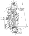
- Figure 1 is a much-simplified, partly cut away, perspective view showing the front of the machine;
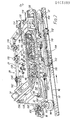
- Figure 2 is an enlarged version of part of Figure 1, showing in particular the capping head of the machine, still somewhat simplified for clarity but in greater detail than Figure 1;
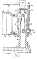
- Figure 3 is a transverse sectional elevation, taken on the line III-III in Figure 9, showing how the capping head is mounted on a base of the machine;
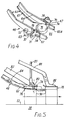
- Figure 4 is a simplifed view of the lower part of the cap chute of the same machine, showing a cap at the pick-up position;
- Figure 5 is a very diagrammatic side elevation showing the lower part of the cap chute and certain components associated therewith, and illustrating the placement of a cap upon a container;
- Figure 6 is a side elevation of the lower part of the cap chute in greater detail;
- Figure 7 is a plan view of the same with certain parts omitted;
- Figure 8 is a simplified side elevation of the capping head, illustrating in particular the manner in which the side belts of the capping machine are mounted and operated, the side belts being shown in their lowermost position;
- Figure 9 is a view corresponding to parts of Figure 8 but shows the side belts in their uppermost position;
- Figure 10 is a simplified side elevation of the sealing assembly of the capping machine, shown during a sealing operation; and
- Figure 11 is similar to Figure 10 but is in two parts, viz. Figure 11(a) and Figure 11(b), wherein Figure 11(a) illustrates the attitude of the sealing assembly upon arrival of a container below it, whilst
- Figure 11(b) illustrates its attitude as the container reaches the downstream end of the assembly.
- Referring to the drawings, the capping machine illustrated therein is a vapour vacuum capping machine for the high-speed capping of jars, bottles and other containers using caps which may be of any suitable kind, the machine being adjustable (as will be seen) so that it can handle a wide variety of shapes and sizes of both containers and caps. However, in the particular application illustrated in Figures 1 and 2 and others of the Figures, the machine is in use for applying "twist- on, twist-off" metal caps to glass jars filled with a foodstuff.
- The capping machine has a casing comprising a
main frame 2 clad withouter panelling 4, to define a workingchamber 6, which has a front access opening 8 and a rear access opening not shown. Each of these access openings has doors such as the door shown at 10. Themain frame 2 supports a conveyor assembly which extends through the capping machine from one side to the other. The conveyor assembly includes anendless conveyor 12 of the flat-plate type, having at one end a drivingdrum 14. The conveyor runs on aflat bed 16. At the left-hand and right-hand ends respectively (as seen in Figure 1) of the machine casing, there are aninlet tunnel 18 and anexit tunnel 20, through which theconveyor 12 passes. Below theconveyor 12, within the casing, is adrive motor 22, coupled to amain gearbox 24 which in turn is coupled, through aconveyor drive shaft 26 having a pair of flexible couplings, to the driving gearbox of theconveyor driving drum 14. - A capping
head 28 is arranged within the workingchamber 6, over theconveyor 12. The cappinghead 28 has an anodisedaluminium body 30 which comprises a horizontaltop portion 29, bent to form anapron portion 32 at the left-hand (inlet) end of the head. At the front and back of thebody 30 at the right-hand (exit) end, a pair of integral wing portions, bent downwardly to formflanges 34 extend outwardly from thetop portion 29. From the rear of thetop portion 29, anintegral mounting bracket 31 extends downwardly. - Referring to Figures 3 and 9, a fixed, upstanding capping
head mounting post 38 is secured to themain frame 2 of the machine. Apost housing 36 comprises a generally-cylindrical portion mounted coaxially on thepost 38 and slidable vertical on the latter. Thepost housing 36 also has an integral, forwardly, extendingportion 36A; the mountingbracket 31 of the capping head body is rigidly secured to theportion 36A so that thehead body 30 is cantilevered from thepost housing 36 and supported thereby. This is the only means of support of the capping head body. - The facility for sliding vertical movement of the
post housing 36 on thepost 38 is provided for the purpose of adjusting the head height, i.e. the height at which thecapping head 28 is positioned above theconveyor 12. This adjustment is made by means of aleadscrew 41 which is mounted rotatably in anupper closure plate 37 of the post housing and which is rotatable by means of a handwheel (Figure 1) andshaft 42, through a headheight adjusting gearbox 40 mounted on theupper closure plate 37. Theshaft 42 is supported in a bearing (not shown) carried by thehead body 30 behind the handwheel. Theleadscrew 41 engages in a threadedbush 39 secured in the top of thepost 38. - The bore of the cylindrical portion of the
post housing 36 is lined with sliding bearing rings 35 which engage thepost 38 itself. The entire static force due to the weight of the cappinghead 28, and any dynamic forces transmitted to thepost 38 from the capping head during operation of the machine, are supported by thepost 38 partly via the bearing rings 35 and partly via theleadscrew 41 andbush 39. However, there is also provided a locking device mounted on the outside of thehead housing 36, to prevent any vertical movement of the capping head taking place due to accidental rotation of the leadscrew 41 (which could for example occur as a result of either inadvertent operation of the handwheel on theshaft 42, or mechanical vibration). The locking device comprises a long,slender locking pin 44 which has a threaded portion carried by arelease nut 43, the latter being captive on thehead housing 36. Thepin 44 extends downwardly from thenut 43 and carries at its lower end awedge member 45 having a vertical face for frictional locking engagement with thepost 38. Thewedge member 45 also has an inclined face engagin a fixedcam element 45A which is part of thepost housing 36. The wedge member extends through aslot 36B formed in the side of the post housing. Rotation of the adjustingnut 43, such as to raise the lockingpin 44, releases the wedge member from frictional locking engagement between thecam element 45A and post 38, thus allowing the cappinghead 28 to be raised or lowered. - Mounted on the
capping head body 30, at the inlet end, is acap heating tunnel 54 provided with means, not shown, for preheating the caps before the latter are delivered to the containers to be closed. An inclined cap feed chute extends downwardly through thetunnel 54 from a suitable supply chute, not shown, which extends through an opening in a portion of the roof of themachine casing 4 that is cut away in Figure 1. Thelower part 46 of the cap feed chute comprises an assembly which is indicated diagrammatically in Figure 1 and shown in more detail in Figure 2 and Figures 4 to 7. Thisassembly 46 will be referred to hereinafter simply as the "cap chute". It will be described more fully hereinafter. - Forward of the
cap chute 46 is a sealinghead assembly 48, carried by the cappinghead body 30. A pair ofendless side belts 50 are carried, one either side of the capping head, by the sealing head assembly which will be described hereinafter. - During the capping operation, a vacuum (as hereinbefore explained) is maintained in the region below the capping
head body 30 by suitable means, being controllable by a mainvacuum control valve 52, Figure 1, mounted on top of thebody 30. The vacuum and the means for creating and maintaining it can be conventional; they form no part of the present invention, and no further discussion of these aspects will be undertaken herein. - In operation, filled
jars 56 are carried by theconveyor 12 through theinlet tunnel 18 into the workingchamber 6, in which each jar first receives a cap, placed upon it at the placement or pick-upposition 58 by thecap chute 46. The cap is then secured and sealed upon the jar by the sealinghead assembly 48, before being carried out of the working chamber through theexit tunnel 20. Each jar is centralised on theconveyor 12 by a pair ofadjustable guides 60, Figure 1, overlying the conveyor in theinlet tunnel 18. Immediately after this, the jars are engaged by theside belts 50 which maintain the jars in their straight central path throughout the capping process. - Referring now to Figures 4 to 7, the
cap chute 46 comprises a pair of cap support rails 62, of gradually decreasing inclination to the horizontal in the usual manner. Eachcap support rail 62 has aside wall 64 and a cap-supportingportion 65, theside walls 64 being spaced apart by slightly more than the diameter of a cap. Thefinal section 65A of each of the cap-supportingportions 65 is narrower than the remainder of theportion 65 upstream of thesection 65A, so as to provide a suitable gap (indicated at 66 in Figure 4) for the passage of the necks of the successive jars through the gap 66. - Referring particularly to Figures 6 and 7, the cap chute is adjustably mounted on a portion 176 (Figure 6) of the capping
body 30, in the following manner. Secured bystuds 174 to thebody portion 176 is a mountingblock 172 carrying atransverse pivot pin 178 which passes through abifurcated centre beam 182 of the cap chute. In this way the latter is hung from the mountingblock 172. Thepin 178 carries a nut securing the cap chute to theblock 172. Upon removal of the nut, thewhole cap chute 46 can be withdrawn for maintenance, replacement or other purposes. The mounting block also includes abracket 184 associated with anadjustment lever 186 which is fixed to the capchute centre beam 182. Thebracket 184 carries an adjustingscrew 188 whereby the spacing between thelever 186 andbracket 184, maintained by acompression spring 190, is adjustable when thepivot pin nut 180 is loosened. In this manner the altitude of the cap chute is adjustable to obtain the required angle of thecap chute section 65A to the horizontal, for feeding thecaps 76 to the jars. - The centre beam has a width-adjusting
shaft 192 mounted through the beam; theshaft 192 has opposed left- and right-hand screw threaded portions, each in screw-threaded engagement with a suitable bracket portion of a respective one of two capchute side plates 194, so that when theshaft 192 is rotated the side plates are moved towards or away from each other. A pair ofstretchers 196 provide the main means for securing theside plates 194 together by means of clampingscrews 198, the latter being released to allow the width between the side plates to be altered when necessary. - Each
cap support rail 62 is fixed to the adjacent one of theside plates 194. It can be seen from the foregoing how therails 62 are mounted so as to be readily adjustable both for transverse width beween them, so that the cap chute can be re-set to accommodate caps of different diameters; and for the optimum altitude in a vertical plane. - Each support
rail side wall 64 has on its outer surface a mountingbracket 63 carrying apivot 72 whereby the rear end of a cap stop roller arm orlever 70 is pivoted about a vertical axis. Theroller arms 70 extend forwardly for some distance, theforward end portion 71 of each arm being directed inwardly through anaperture 67 in theside wall 64; at the free end of theend portion 71, each roller arm carries acap stop roller 74, which is freely rotatable about its own axis. The axes of thestop rollers 74 are so orientated as to lie parallel to each other and substantially parallel to the axis of acap 76 when the latter is lying, as shown in Figure 4, with its skirt engaging the two stop rollers. In this position, each cap in turn is arrested by therollers 74 in its gravity-induced slide down the cap chute; in this position also, the cap becomes engaged by itsjar 56 for the first time. For the purpose of arresting the cap, thestop rollers 74 overlie thefinal section 65A of the cap-supportingrail portions 65, the rollers protruding through theapertures 67. They are biassed towards this normal position by tension springs 78 connected between therespective roller arms 70 and the associatedside walls 64. Thesprings 78 are mounted on top of therespective side walls 64, in an exposed position in which they are readily available for inspection and, if necessary, replacement. - Attached by a
spring clip 200 to the mountingblock bracket 184 is apin 202 on which one end of a pair ofarms arm 82 is pivoted to avertical push rod 83 carrying arear presser foot 80. The other end of thearm 88 carries aforward presser foot 86; thearm 88 is pivoted about half-way along its length to avertical push rod 85. The presser feet and their linkages are omitted for clarity from Figure 7. - The operation of placing a
cap 76 upon ajar 56 at the pick-upstation 58 is illustrated in Figure 5, in which the cap is indicated, in the same position as in Figure 4, by full lines. Behind it there are indicated in phantom lines, some following caps in the cap chute, awaiting their turn for placement. Thecap 76 at the pick-up station is held down against the cap-supportingportions 65 of therails 62 by therear presser foot 80. The pressure exerted on thecap 76 by thepresser foot 80 is adjustable, through thepush rod 83, by means of an adjuster 92 (Figure 2) mounted on top of thebody 30. When thejar 56 arrives below thecap 76 at the pick-up station (as indicated by phantom lines in Figure 5), the leadingportion 84 of the lip around the mouth of the jar engages the corresponding portion of the inner surface of the cap skirt in the usual way. Continued forward movement of the jar (caused by theconveyor 12 and theside belts 50, which are all moving at exactly the same forward speed) causes the jar to push the cap forward, thestop rollers 74 retracting away from each other against the tension springs 78. However, so long as some part of the cap skirt is interrupting the transverse path of the stop rollers between their retracted and normal positions, the cylindrical faces of therollers 74 roll upon, and apply pressure to, the cap skirt, so maintaining its axial orientation. Thereafter, the rear portion of the cap skirt falls on to the top of the jar. Immediately after the cap has left the cap chute, it is restrained laterally by resilient side guides 89 carried by the cap chute side plates 194 (Figures 2, 6 and 7), and axially by theforward presser shoe 86. The axial pressure exerted by theforward presser shoe 86 upon thecap 76 is adjustable in the same manner as that exerted by therear presser shoe 80, as described above, by a similar adjuster 90 (Figure 2) acting through thepush rod 85. - Reference is now made to Figures 2, 8 and 9. Each
endless side belt 50, presenting a working or jar-engaging portion 94 and an outer or idle portion 96 (Figure 2) is carried by a pair of side belt pulleys 98,100, one at each extreme end of the capping head. The rear side belt pulleys 98 are freely rotatable, on vertical axes, at the ends ofsupport arms 102 which are pivoted to across-beam 104. Thesupport arms 102 are biassed by side belt tensioning springs 106. Thecross-beam 104 is fixed at each of its ends to the rear end of a respective one of a pair of side belt frames or supportbeams 108 extending along the capping head at either side of the latter. Eachsupport beam 108 carries a plurality of sidebelt locating shoes 110 along which the working portion 94 of the side belt runs. - In this example, there are two locating
shoes 110 to eachsupport beam 108. The locatingshoes 110 at each side of the capping head serve to maintain the working portion 94 of the respective side belt in a straight configuration and at the correct transverse distance from the working portion of-theother belt 50. With this in view, the transverse distances of the locatingshoes 110 from their side belt support beams 108 are adjustable by means ofsuitable adjusters 112, Figure 2. - The leading side belt pulleys 100 are each carried by a respective side
belt pulley gearbox 114 fixed to the front end of thecorresponding support beam 108. The pulley gearboxes 114 are coupled together by a transversefinal drive shaft 116 which is driven by achain drive 118 from a main drivenshaft 120. Theshaft 120 is cantilevered from a spiral-bevel gearbox 122 mounted at the back of thecapping head body 30. Thegearbox 122 is driven by a verticalmain drive shaft 124 which is, in turn, driven by themain gearbox 24, so that the drivenshaft 120 and theside belts 50 are all driven, in synchronism with theconveyor 12, by themotor 22. - The manner in which the side belt support beams 108 are mounted in the capping head will now be described. Each
beam 108 carries twopivots 126, one near each end of the beam. These four pivots lie in a common horizontal plane which is parallel with the top of theconveyor 12. Pivoted at thepivots 126 to thebeams 108, and thus connecting the latter together transversely, are two rigid crossmembers 128,130. Therearward cross-member 128 has a transversely-extending portion joining a pair of side crank portions 132,134, each of which carries the appropriate element of therespective pivot 126 and is also pivoted about a transverse axis (common to the pivots of both crank portions) to thecapping head body 30 as indicated at 136. Therear crank portion 134 has an upstanding portion to which is pivoted one end of ahorizontal tie bar 138. - The
forward cross-member 130 also comprises a transversely-extending portion joining a pair of side crank portions, each pivoted to thebeam 108 by therespective pivot 126 and also being pivoted to thecapping head body 30 about a transverse axis at 140. Theaxes conveyor 12. - The front end of the
horizontal tie bar 138 is pivoted to the transverse portion of theforward cross-member 130. Thetie bar 138 has a threadedportion 142, which passes through aU-shaped bracket 144 secured to the top of thecapping head body 30. An adjustingnut 146 is threaded on to theportion 142 and held captive in thebracket 144. - It will now be seen that the side belt support beams 108 are carried in the capping head by a parallelogram-type linkage comprising the beams themselves as lower horizontal members, the
tie bar 138 as the upper horizontal member, and, as the side members, thecross members side belts 50 and the top of the conveyor 12 (the "side belt height") is infinitely adjustable within a predetermined range by simply turning thenut 146 by means of a spanner, so as to move thetie bar 138 to the right (as seen in Figures 8 and 9) to lower the side belts, and to the left in order to raise them. - The use of the
chain drive 118 enables this adjustment to be made without disturbing the motion of theside belts 50. - Figures 8 and 9 show two containers of different shapes on the
conveyor 12, each container having a cylindrical portion in a different position, and the side belts being adjusted in each case to engage that cylindrical portion. - Referring now to Figure 10, the sealing head assembly comprises a pair of sealing
belt drums shaft 120 already described, and therefore rotated continuously in synchronism with theconveyor 12 and theside belts 50. A pair of endless sealing belts 152,154 extend around the respective drums 148,150 and around respective, rearwardly-disposed, idler pulleys 156. Thepulleys 156 are carried by brackets 157 (Figure 2) which are carried, via a spring-tensioning device, not shown, to maintain tension in thebelts shoe 158. Thebrackets 157 are omitted from Figures 10 and 11 for clarity. The sealingshoe 158 extends generally horizontally and has a flat lower surface overlying, and in contact with, the lower runs of both of the sealingbelts - The sealing shoe is pivoted to the forward end of each of a
forward suspension arm 160 and arearward suspension arm 162. Both of these suspension arms are pivoted, at theirrear ends 164, to thecapping head body 30. (These pivots are out of sight in Figure 2). To each of thesuspension arms shoe 158, there is pivoted a respective one of a pair ofvertical hanger rods 166, each of which is suspended by its top end, through acompression spring 168, from the cappinghead body 30. Thesprings 168 cause the sealingshoe 158 to exert upon thecaps 76, through the sealingbelts jars 56. This force is adjustable by means of spring adjusters 170 (Figure 2) incorporated in the mountings of the compression springs 168. At the same time, because of the difference between the diameters of the sealingbelt drums belts caps 76 in contact therewith. In this manner, whilst the axial downward force is exerted by the sealingshoe 158, thecaps 76 are secured sealingly to theirjars 56. - Figure 11(a) illustrates by a heavy arrow the upward reaction force, compressing the
rear spring 168, imposed upon the sealing head assembly when a container, carrying a cap, initially arrives under the sealing shoe; whilst Figure 11(b) illustrates by a similar arrow the reaction force when the capped container is about to pass from below the sealing shoe. It should be noted that in both cases, it is assumed that no other container lies under the sealing head assembly; such a case is however illustrated in Figure 10, in which both of thesprings 168 are compressed. Thus the downward tilt of the front or rear end of the sealing head assembly, evident in Figures 11(a) and (b) respectively, is absent from Figure 10.
Claims (23)
Priority Applications (2)
| Application Number | Priority Date | Filing Date | Title |
|---|---|---|---|
| DE8686200037T DE3379785D1 (en) | 1982-08-17 | 1983-08-04 | Capping machines |
| AT83304502T ATE30897T1 (en) | 1982-08-17 | 1983-08-04 | VESSEL CLOSING MACHINE. |
Applications Claiming Priority (2)
| Application Number | Priority Date | Filing Date | Title |
|---|---|---|---|
| GB8223653 | 1982-08-17 | ||
| GB08223653A GB2125379B (en) | 1982-08-17 | 1982-08-17 | Capping machines |
Related Child Applications (1)
| Application Number | Title | Priority Date | Filing Date |
|---|---|---|---|
| EP86200037.9 Division-Into | 1983-08-04 |
Publications (3)
| Publication Number | Publication Date |
|---|---|
| EP0103389A2 true EP0103389A2 (en) | 1984-03-21 |
| EP0103389A3 EP0103389A3 (en) | 1984-07-11 |
| EP0103389B1 EP0103389B1 (en) | 1987-11-19 |
Family
ID=10532355
Family Applications (2)
| Application Number | Title | Priority Date | Filing Date |
|---|---|---|---|
| EP86200037A Expired EP0184583B1 (en) | 1982-08-17 | 1983-08-04 | Capping machines |
| EP83304502A Expired EP0103389B1 (en) | 1982-08-17 | 1983-08-04 | Capping machines |
Family Applications Before (1)
| Application Number | Title | Priority Date | Filing Date |
|---|---|---|---|
| EP86200037A Expired EP0184583B1 (en) | 1982-08-17 | 1983-08-04 | Capping machines |
Country Status (19)
| Country | Link |
|---|---|
| US (1) | US4608806A (en) |
| EP (2) | EP0184583B1 (en) |
| JP (2) | JPS5984788A (en) |
| AT (1) | ATE42728T1 (en) |
| AU (2) | AU555562B2 (en) |
| CA (1) | CA1215694A (en) |
| DD (1) | DD215519A5 (en) |
| DE (1) | DE3374554D1 (en) |
| DK (1) | DK156048C (en) |
| ES (1) | ES525552A0 (en) |
| FI (1) | FI77002C (en) |
| GB (1) | GB2125379B (en) |
| GR (1) | GR79633B (en) |
| HU (1) | HUH3044A (en) |
| IE (1) | IE54565B1 (en) |
| NO (2) | NO161435C (en) |
| PL (1) | PL138677B1 (en) |
| PT (1) | PT77201B (en) |
| SU (2) | SU1537132A3 (en) |
Families Citing this family (19)
| Publication number | Priority date | Publication date | Assignee | Title |
|---|---|---|---|---|
| GB8901460D0 (en) * | 1989-01-24 | 1989-03-15 | Glover Clive E | Capping device |
| US5012630A (en) * | 1990-03-01 | 1991-05-07 | Owens-Illinois Closure Inc. | Closure application system |
| US5218811A (en) * | 1992-05-27 | 1993-06-15 | Diversified Capping Equipment, Inc. | Closure pre-tightening mechanism for a container filling and capping system |
| US6941724B2 (en) * | 2001-06-07 | 2005-09-13 | Klockner Khs, Inc. | Screw capping head |
| DE10352016B3 (en) * | 2003-11-07 | 2005-08-11 | Khs Maschinen- Und Anlagenbau Ag | Closing machine for closing vessels |
| US7032363B1 (en) * | 2004-10-19 | 2006-04-25 | Tetra Laval Holdings & Finance, Sa | Linear fitment applicator and method |
| US7325369B2 (en) * | 2006-02-21 | 2008-02-05 | Luc Jalbert | Apparatus including a differential for rotating a cap relatively to a container |
| JP2010070248A (en) * | 2008-09-22 | 2010-04-02 | Shibuya Kogyo Co Ltd | Capper |
| IT1395607B1 (en) * | 2009-09-14 | 2012-10-16 | Ft System Srl | FILLING SYSTEM FOR BOTTLES OR CONTAINERS WITH CONTINUOUS CALIBRATION AND A CONTINUOUS CALIBRATION METHOD OF SUCH A SYSTEM |
| ES2431267B1 (en) * | 2013-05-24 | 2014-09-10 | José Francisco González Sánchez | Tooling for mounting a protective cap on a container and a method for placing a protective cap on a container |
| US9751741B2 (en) * | 2014-07-23 | 2017-09-05 | Xentiq Partners Pte Ltd | Dispensing apparatus, method of dispensing, capping apparatus and method of capping |
| US10351405B2 (en) * | 2016-02-11 | 2019-07-16 | NJM Packaging Inc. | Capping machine |
| EP3205589B1 (en) * | 2016-02-12 | 2019-04-03 | Tetra Laval Holdings & Finance S.A. | A distribution unit for feeding lids to necks of containers |
| US20180346158A1 (en) * | 2017-06-02 | 2018-12-06 | Inline Plastics Corp. | Closure Systems and Methods For Containers |
| IT202100014288A1 (en) * | 2021-06-01 | 2022-12-01 | Sasib Spa | Machine for the packaging of tobacco industry products |
| CN113979393A (en) * | 2021-09-14 | 2022-01-28 | 苏州得一鲜食品科技有限公司 | Packaging equipment and packaging method for food can |
| US11993414B2 (en) * | 2021-12-13 | 2024-05-28 | Boomerang Water, Llc | Cleaning, filling, and capping containers |
| FR3139805A1 (en) * | 2022-09-20 | 2024-03-22 | Coudert Constructions | Device for screwing a capsule onto a packaging body |
| CN115991452B (en) * | 2023-03-22 | 2023-06-27 | 江苏尚纯自动化技术有限公司 | Packing machine with height-adjustable gland |
Citations (8)
| Publication number | Priority date | Publication date | Assignee | Title |
|---|---|---|---|---|
| US2256415A (en) * | 1938-08-19 | 1941-09-16 | Crown Cork & Seal Co | Container sealing apparatus |
| US2319214A (en) * | 1940-04-17 | 1943-05-18 | White Cap Co | Sealing apparatus |
| US2876605A (en) * | 1958-06-19 | 1959-03-10 | White Cap Co | Machine for applying rotatable closure caps to containers |
| US3054234A (en) * | 1960-02-05 | 1962-09-18 | Anchor Hocking Glass Corp | Sealing machine and method |
| US3071909A (en) * | 1960-04-22 | 1963-01-08 | Anchor Hocking Glass Corp | Screw cap applicator |
| US3274748A (en) * | 1963-05-10 | 1966-09-27 | Anchor Hocking Glass Corp | Sealing machine and method |
| US3438174A (en) * | 1965-02-11 | 1969-04-15 | Anchor Hocking Glass Corp | Container sealing machine |
| US4279115A (en) * | 1979-03-12 | 1981-07-21 | Anchor Hocking Corporation | High speed straight line container sealing machine |
Family Cites Families (12)
| Publication number | Priority date | Publication date | Assignee | Title |
|---|---|---|---|---|
| CA597618A (en) * | 1960-05-10 | L. Day Carl | Container sealing apparatus | |
| GB394480A (en) * | 1931-06-03 | 1933-06-29 | Standard Cap & Seal Corp | Improvements in bottle capping mechanism |
| GB646441A (en) * | 1946-09-20 | 1950-11-22 | Anchor Hocking Glass Corp | Improvements relating to machines for applying and sealing closure caps to bottles, jars, cans and like containers |
| GB1071008A (en) * | 1965-11-17 | 1967-06-07 | Skane Emballage Ab | A device for placing threaded closures on containers |
| US3559365A (en) * | 1968-02-27 | 1971-02-02 | Haskon Inc | Capping apparatus and method |
| US3800501A (en) * | 1972-02-03 | 1974-04-02 | Continental Can Co | Cap feeding apparatus |
| US3803800A (en) * | 1973-02-09 | 1974-04-16 | Neuvelle Baele Gangloff Racine | Device for fitting bottle and container caps |
| US3905177A (en) * | 1973-10-29 | 1975-09-16 | Michael Herzog | Bottle capping machine |
| SU571432A1 (en) * | 1975-12-18 | 1977-09-05 | Всесоюзный Научно-Исследовательский Кинофотоинститут | Device for putting lids onto cylindrical containers |
| US4199914A (en) * | 1978-09-08 | 1980-04-29 | Anchor Hocking Corporation | Sealing machine closure cap pickup |
| SE7908966L (en) * | 1978-11-15 | 1980-05-16 | Schmalbach Lubeca | DEVICE FOR APPLICATION OF SCREW LOCK / CAPSYLES ON STORAGE BOILERS |
| IT1163993B (en) * | 1979-05-08 | 1987-04-08 | Italcaps Spa | PROCEDURE FOR THE PRE-CLOSURE WITH VESSEL CAPSULES CONTAINING PRODUCTS THAT MAY BE EDGEED AND A DEVICE TO REALIZE IT |
-
1982
- 1982-08-17 GB GB08223653A patent/GB2125379B/en not_active Expired
-
1983
- 1983-08-04 EP EP86200037A patent/EP0184583B1/en not_active Expired
- 1983-08-04 DE DE8383304502T patent/DE3374554D1/en not_active Expired
- 1983-08-04 EP EP83304502A patent/EP0103389B1/en not_active Expired
- 1983-08-04 AT AT86200037T patent/ATE42728T1/en not_active IP Right Cessation
- 1983-08-08 US US06/521,107 patent/US4608806A/en not_active Expired - Fee Related
- 1983-08-09 AU AU17817/83A patent/AU555562B2/en not_active Ceased
- 1983-08-11 GR GR72195A patent/GR79633B/el unknown
- 1983-08-12 IE IE1900/83A patent/IE54565B1/en not_active IP Right Cessation
- 1983-08-12 PT PT77201A patent/PT77201B/en not_active IP Right Cessation
- 1983-08-16 HU HU832881A patent/HUH3044A/en unknown
- 1983-08-16 SU SU833650403A patent/SU1537132A3/en active
- 1983-08-16 NO NO832942A patent/NO161435C/en unknown
- 1983-08-16 CA CA000434730A patent/CA1215694A/en not_active Expired
- 1983-08-16 FI FI832943A patent/FI77002C/en not_active IP Right Cessation
- 1983-08-16 DK DK375183A patent/DK156048C/en not_active IP Right Cessation
- 1983-08-17 PL PL1983243446A patent/PL138677B1/en unknown
- 1983-08-17 ES ES525552A patent/ES525552A0/en active Granted
- 1983-08-17 DD DD83254034A patent/DD215519A5/en unknown
- 1983-08-17 JP JP58149270A patent/JPS5984788A/en active Granted
-
1985
- 1985-04-29 SU SU853888448A patent/SU1398769A3/en active
- 1985-09-26 NO NO853788A patent/NO853788L/en unknown
-
1986
- 1986-04-11 AU AU56032/86A patent/AU572390B2/en not_active Ceased
-
1987
- 1987-09-16 JP JP62229942A patent/JPS63178984A/en active Pending
Patent Citations (8)
| Publication number | Priority date | Publication date | Assignee | Title |
|---|---|---|---|---|
| US2256415A (en) * | 1938-08-19 | 1941-09-16 | Crown Cork & Seal Co | Container sealing apparatus |
| US2319214A (en) * | 1940-04-17 | 1943-05-18 | White Cap Co | Sealing apparatus |
| US2876605A (en) * | 1958-06-19 | 1959-03-10 | White Cap Co | Machine for applying rotatable closure caps to containers |
| US3054234A (en) * | 1960-02-05 | 1962-09-18 | Anchor Hocking Glass Corp | Sealing machine and method |
| US3071909A (en) * | 1960-04-22 | 1963-01-08 | Anchor Hocking Glass Corp | Screw cap applicator |
| US3274748A (en) * | 1963-05-10 | 1966-09-27 | Anchor Hocking Glass Corp | Sealing machine and method |
| US3438174A (en) * | 1965-02-11 | 1969-04-15 | Anchor Hocking Glass Corp | Container sealing machine |
| US4279115A (en) * | 1979-03-12 | 1981-07-21 | Anchor Hocking Corporation | High speed straight line container sealing machine |
Also Published As
Similar Documents
| Publication | Publication Date | Title |
|---|---|---|
| US4608806A (en) | Capping machines | |
| US3771284A (en) | Capping apparatus | |
| AU2011201284B2 (en) | Packaging machine | |
| US5586637A (en) | Variable angle conveyor assembly with stepped cleat | |
| US6115992A (en) | Apparatus and method for pre-capping containers | |
| US4199914A (en) | Sealing machine closure cap pickup | |
| US5423159A (en) | Pivoting roller assembly for tightening container caps | |
| US3444982A (en) | Device for handling and positioning articles within containers | |
| US5012630A (en) | Closure application system | |
| US4070854A (en) | Apparatus for removing bottle caps | |
| US3214887A (en) | Container fitment applying machine | |
| US3435587A (en) | Self-adjusting cap applying mechanism | |
| US3850284A (en) | Container sealing machine side belt system | |
| US4308707A (en) | Closure pre-tightener for closure applicating machines | |
| US2942394A (en) | Container closing apparatus | |
| US5558489A (en) | Mass feeder for product delivery system | |
| US5150559A (en) | Fluid container capper apparatus | |
| US3175337A (en) | Container headspacer | |
| CA1228579A (en) | Capping machines | |
| GB2161150A (en) | Capping machines | |
| US2735600A (en) | Apparatus for sealing containers | |
| JP7455306B2 (en) | capper | |
| FI77003B (en) | FOERSLUTNINGSMASKIN FOER ANBRINGANDE AV LOESTAGBARA TILLSLUTNINGSDELAR PAO BEHAOLLARE. | |
| US2600285A (en) | Head spacing mechanism | |
| JPH0417844B2 (en) |
Legal Events
| Date | Code | Title | Description |
|---|---|---|---|
| PUAI | Public reference made under article 153(3) epc to a published international application that has entered the european phase |
Free format text: ORIGINAL CODE: 0009012 |
|
| AK | Designated contracting states |
Designated state(s): AT BE CH DE FR GB IT LI LU NL SE |
|
| PUAL | Search report despatched |
Free format text: ORIGINAL CODE: 0009013 |
|
| AK | Designated contracting states |
Designated state(s): AT BE CH DE FR GB IT LI LU NL SE |
|
| 17P | Request for examination filed |
Effective date: 19840720 |
|
| R17P | Request for examination filed (corrected) |
Effective date: 19840804 |
|
| R17P | Request for examination filed (corrected) |
Effective date: 19840720 |
|
| GRAA | (expected) grant |
Free format text: ORIGINAL CODE: 0009210 |
|
| AK | Designated contracting states |
Kind code of ref document: B1 Designated state(s): AT BE CH DE FR GB IT LI LU NL SE |
|
| REF | Corresponds to: |
Ref document number: 30897 Country of ref document: AT Date of ref document: 19871215 Kind code of ref document: T |
|
| REF | Corresponds to: |
Ref document number: 3374554 Country of ref document: DE Date of ref document: 19871223 |
|
| ET | Fr: translation filed | ||
| ITF | It: translation for a ep patent filed | ||
| PLBE | No opposition filed within time limit |
Free format text: ORIGINAL CODE: 0009261 |
|
| STAA | Information on the status of an ep patent application or granted ep patent |
Free format text: STATUS: NO OPPOSITION FILED WITHIN TIME LIMIT |
|
| 26N | No opposition filed | ||
| PGFP | Annual fee paid to national office [announced via postgrant information from national office to epo] |
Ref country code: FR Payment date: 19910708 Year of fee payment: 9 |
|
| PGFP | Annual fee paid to national office [announced via postgrant information from national office to epo] |
Ref country code: AT Payment date: 19910709 Year of fee payment: 9 |
|
| PGFP | Annual fee paid to national office [announced via postgrant information from national office to epo] |
Ref country code: SE Payment date: 19910712 Year of fee payment: 9 Ref country code: GB Payment date: 19910712 Year of fee payment: 9 |
|
| PGFP | Annual fee paid to national office [announced via postgrant information from national office to epo] |
Ref country code: CH Payment date: 19910716 Year of fee payment: 9 |
|
| PGFP | Annual fee paid to national office [announced via postgrant information from national office to epo] |
Ref country code: LU Payment date: 19910729 Year of fee payment: 9 Ref country code: DE Payment date: 19910729 Year of fee payment: 9 Ref country code: BE Payment date: 19910729 Year of fee payment: 9 |
|
| ITTA | It: last paid annual fee | ||
| PGFP | Annual fee paid to national office [announced via postgrant information from national office to epo] |
Ref country code: NL Payment date: 19910831 Year of fee payment: 9 |
|
| EPTA | Lu: last paid annual fee | ||
| PG25 | Lapsed in a contracting state [announced via postgrant information from national office to epo] |
Ref country code: LU Free format text: LAPSE BECAUSE OF NON-PAYMENT OF DUE FEES Effective date: 19920804 Ref country code: GB Effective date: 19920804 Ref country code: AT Effective date: 19920804 |
|
| PG25 | Lapsed in a contracting state [announced via postgrant information from national office to epo] |
Ref country code: SE Effective date: 19920805 |
|
| PG25 | Lapsed in a contracting state [announced via postgrant information from national office to epo] |
Ref country code: LI Effective date: 19920831 Ref country code: CH Effective date: 19920831 Ref country code: BE Effective date: 19920831 |
|
| BERE | Be: lapsed |
Owner name: METAL BOX P.L.C. Effective date: 19920831 |
|
| PG25 | Lapsed in a contracting state [announced via postgrant information from national office to epo] |
Ref country code: NL Effective date: 19930301 |
|
| GBPC | Gb: european patent ceased through non-payment of renewal fee |
Effective date: 19920804 |
|
| NLV4 | Nl: lapsed or anulled due to non-payment of the annual fee | ||
| PG25 | Lapsed in a contracting state [announced via postgrant information from national office to epo] |
Ref country code: FR Effective date: 19930430 |
|
| REG | Reference to a national code |
Ref country code: CH Ref legal event code: PL |
|
| PG25 | Lapsed in a contracting state [announced via postgrant information from national office to epo] |
Ref country code: DE Effective date: 19930501 |
|
| REG | Reference to a national code |
Ref country code: FR Ref legal event code: ST |
|
| EUG | Se: european patent has lapsed |
Ref document number: 83304502.4 Effective date: 19930307 |