EP0184295A2 - Hängedeckenkonstruktion - Google Patents
Hängedeckenkonstruktion Download PDFInfo
- Publication number
- EP0184295A2 EP0184295A2 EP85307228A EP85307228A EP0184295A2 EP 0184295 A2 EP0184295 A2 EP 0184295A2 EP 85307228 A EP85307228 A EP 85307228A EP 85307228 A EP85307228 A EP 85307228A EP 0184295 A2 EP0184295 A2 EP 0184295A2
- Authority
- EP
- European Patent Office
- Prior art keywords
- panels
- members
- beams
- supporting member
- suspended ceiling
- Prior art date
- Legal status (The legal status is an assumption and is not a legal conclusion. Google has not performed a legal analysis and makes no representation as to the accuracy of the status listed.)
- Granted
Links
Images


Classifications
-
- E—FIXED CONSTRUCTIONS
- E04—BUILDING
- E04B—GENERAL BUILDING CONSTRUCTIONS; WALLS, e.g. PARTITIONS; ROOFS; FLOORS; CEILINGS; INSULATION OR OTHER PROTECTION OF BUILDINGS
- E04B9/00—Ceilings; Construction of ceilings, e.g. false ceilings; Ceiling construction with regard to insulation
- E04B9/06—Ceilings; Construction of ceilings, e.g. false ceilings; Ceiling construction with regard to insulation characterised by constructional features of the supporting construction, e.g. cross section or material of framework members
-
- E—FIXED CONSTRUCTIONS
- E04—BUILDING
- E04B—GENERAL BUILDING CONSTRUCTIONS; WALLS, e.g. PARTITIONS; ROOFS; FLOORS; CEILINGS; INSULATION OR OTHER PROTECTION OF BUILDINGS
- E04B9/00—Ceilings; Construction of ceilings, e.g. false ceilings; Ceiling construction with regard to insulation
- E04B9/22—Connection of slabs, panels, sheets or the like to the supporting construction
- E04B9/24—Connection of slabs, panels, sheets or the like to the supporting construction with the slabs, panels, sheets or the like positioned on the upperside of, or held against the underside of the horizontal flanges of the supporting construction or accessory means connected thereto
- E04B9/26—Connection of slabs, panels, sheets or the like to the supporting construction with the slabs, panels, sheets or the like positioned on the upperside of, or held against the underside of the horizontal flanges of the supporting construction or accessory means connected thereto by means of snap action of elastically deformable elements held against the underside of the supporting construction
-
- E—FIXED CONSTRUCTIONS
- E04—BUILDING
- E04B—GENERAL BUILDING CONSTRUCTIONS; WALLS, e.g. PARTITIONS; ROOFS; FLOORS; CEILINGS; INSULATION OR OTHER PROTECTION OF BUILDINGS
- E04B9/00—Ceilings; Construction of ceilings, e.g. false ceilings; Ceiling construction with regard to insulation
- E04B9/34—Grid-like or open-work ceilings, e.g. lattice type box-like modules, acoustic baffles
- E04B9/36—Grid-like or open-work ceilings, e.g. lattice type box-like modules, acoustic baffles consisting of parallel slats
- E04B9/366—Grid-like or open-work ceilings, e.g. lattice type box-like modules, acoustic baffles consisting of parallel slats the principal plane of the slats being vertical
-
- Y—GENERAL TAGGING OF NEW TECHNOLOGICAL DEVELOPMENTS; GENERAL TAGGING OF CROSS-SECTIONAL TECHNOLOGIES SPANNING OVER SEVERAL SECTIONS OF THE IPC; TECHNICAL SUBJECTS COVERED BY FORMER USPC CROSS-REFERENCE ART COLLECTIONS [XRACs] AND DIGESTS
- Y10—TECHNICAL SUBJECTS COVERED BY FORMER USPC
- Y10S—TECHNICAL SUBJECTS COVERED BY FORMER USPC CROSS-REFERENCE ART COLLECTIONS [XRACs] AND DIGESTS
- Y10S160/00—Flexible or portable closure, partition, or panel
- Y10S160/90—Vertical type venetian blind
Definitions
- the present invention relates to suspended ceiling assembies.
- suspended ceilings have been proposed, one particular type involves a number of generally parallelly arranged support beams upon which are mounted, usually at right angles to the support beams, a large number of panels which can be spaced apart from one another.
- the panels extend generally vertically downwardly, but there are many other types in which the panels are at an angle to the vertical or indeed are horizontal.
- the arrangement of 7 404 321 utilizes a supporting member for each panel in each beam, the supporting member having a tongue which engages in an appropriate aperture in the beam. In order to move the beam one has to disengage each tongue and maintain it disengaged relative to the several apertures in order to sweep several panels to an out-of-the-way position.
- 7 213 187 utilizes rigid spacer bars between adjacent supporting members and these each have to be removed to enable the supporting members to be brought together which is a cumbersome operation.
- 7 426 096 utilizes a sprung-loaded ball engageable in a detent in the beam and this does not provide a really satisfactory positive positioning of the panel and the supporting members can readily become dislodged or misaligned.
- the supporting members and the elongate panels supported thereby to be arranged in at least one group, and for the positioning means to comprise distance members, which interconnect supporting members or panels of the group supported thereby, in a manner to allow a preselected maximum mutual spacing between the panels of the group and unhindered closing of the mutual spacings upon displacement of said panels and supporting members along said two support beams, in a direction to remove the panels from a certain ceiling area at least one supporting member of a first end panel of the group, cooperating with a locking means releasably to lock the position of said first end panel supporting member with respect to its beam, and at least one further supporting member of the other end panel of the group cooperating with a fixing means for holding the other end panel supporting member in a predetermined position with respect to its beam.
- each panel of the assembly is preferably at an angle to the plane including the longitudinal axes for the beams and thus, for example, the general plane of each panel may be vertical. It is also contemplated that the arrangement of the invention could also be employed with generally horizontal panels but the scope for moving the the panels towards one another would then be significantly reduced.
- the fixing means are similar to or identical with the locking member or members.
- the support beams may each comprise, at least at or adjacent to the positions to be occupied by the relevant supporting member of the end panels of a group, when the panels are at their maximum mutual spacing, locating means, such as ribs, recesses or apertures, and the fixing means and/or the locking means may each comprise clips engageable with one of the locating means, said clip having a surface engageable by the relevant supporting member of the end panel of the group to maintain said supporting member in said position.
- the beams will normally be of channel shaped cross- section with their webs uppermost and said locating means comprise apertures formed in the webs, the clips including a body portion extending beside the outside of one flange of the channel and an upper arm extends over a portion of the web, with the projection on the upper arm engaging in the aperture to locate the clip in place, and a lower arm extends under the flange, the side of the arm being engageable by a supporting member to hold the supporting member in position.
- each clip can then have an upturned tab which is lockably engageable against the inner surface of the rim to retain the clip in place and each clip can include a tongue which can be manually grasped to disengage the tab from the rim to enable the clip to be removed.
- the distancing members can take many different forms. For example they can be formed by rods, strips or the like, each distance member being carried by a supporting member and slidably and engageably cooperating with the adjacent supporting member, said distance members being interchangeable to give a different preselected spacing between adjacent panels. Similarly, they could be in the form of wires which can, for example, have a loop passed over a post on the supporting member and having a locking looped tail which is engaged by the upturned tip of an adjacent wire distance member. Alternatively, they can be in the form of cords or of bead chains.
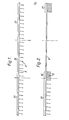
- a beam 8 which is one of several such beams extending parallel to one another, the beams 8 having located therebelow several parallel generally vertically extending elongate panels 9, with the length of the panels 9 being at an angle, e.g. 90°, to the length of the beams 8.
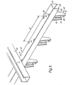
- Figure 3 illustrates more clearly the beams 8 as being carried by stringers 10, the beams 8 being of inverted channel section having a web 11, side flanges 12, the free ends of which are formed with inturned rims 13.
- a supporting member 14 comprises two downwardly extending parallel spaced apart limbs 15, 16, the limb 15 having an inwardly extending lug 17 while the limb 16 has lower and upper lugs 18 and 19, the lugs 17, 18, 19 each being formed in an inwardly projecting fin 20.
- the supporting member comprises a neck 21 which can pass between the rims 13 of the channel and a head 22 which can be snap-fitted behind the rims 13.
- the supporting members 14 and their panels 9 are arranged, as can be seen in Figures 1 and 2, in several groups indicated by the reference numeral 25, 26 and 27 although, of course, more than three groups will usually be provided.
- the groups are arranged in their normal position, that is with the panels 9 all equally spaced.
- Figure 5 illustrates a preferred construction in which the spacing members comprise a metal or plastic strip 34 having bent ends 35 and punched out tangs 36 adjacent the end. These tangs engage on a bridge (not shown) on the adjacent supporting member 14 to maintain the correct spacing therebetween.
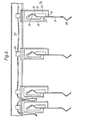
- the clips 37 include a body 38 which extends adjacent to the flange 12 of the beam 8, an upper arm 39 extends over the rim 11, the free end of the upper arm having a downwardly extending projection 40 which can engage in an aperture 41 which is appropriately positioned on the beam.
- a lower arm 42 of the clip is provided with an upturned tab 43 which can engage against a rim 13 to hold the clip in place and this can be released by a tongue 44 being grasped and pulled away to the right, as shown in Figure 4.
- the clip 37 can be positioned against an end supporting member 14 of a group 25, 26 or 27, to act as a fixing means, the remaining supporting members then being pulled away from one another so that their mutual spacing is determined by the distance members in the form of the cord 29, wire 30 or strip 34 and then a further clip is placed in the appropriate aperture 41 adjacent the other end supporting member of the group, to act as a locking means to hold all of the supporting members in their desired position.
Landscapes
- Engineering & Computer Science (AREA)
- Architecture (AREA)
- Electromagnetism (AREA)
- Civil Engineering (AREA)
- Structural Engineering (AREA)
- Physics & Mathematics (AREA)
- Vehicle Interior And Exterior Ornaments, Soundproofing, And Insulation (AREA)
- Supports For Pipes And Cables (AREA)
- Residential Or Office Buildings (AREA)
- Conveying And Assembling Of Building Elements In Situ (AREA)
- Joining Of Building Structures In Genera (AREA)
- Building Environments (AREA)
- Seats For Vehicles (AREA)
- Clamps And Clips (AREA)
- Laminated Bodies (AREA)
- Tents Or Canopies (AREA)
Priority Applications (1)
| Application Number | Priority Date | Filing Date | Title |
|---|---|---|---|
| AT85307228T ATE52121T1 (de) | 1984-12-06 | 1985-10-09 | Haengedeckenkonstruktion. |
Applications Claiming Priority (2)
| Application Number | Priority Date | Filing Date | Title |
|---|---|---|---|
| GB8430813 | 1984-12-06 | ||
| GB08430813A GB2168090B (en) | 1984-12-06 | 1984-12-06 | Suspended ceiling |
Publications (3)
| Publication Number | Publication Date |
|---|---|
| EP0184295A2 true EP0184295A2 (de) | 1986-06-11 |
| EP0184295A3 EP0184295A3 (en) | 1987-05-13 |
| EP0184295B1 EP0184295B1 (de) | 1990-04-18 |
Family
ID=10570785
Family Applications (1)
| Application Number | Title | Priority Date | Filing Date |
|---|---|---|---|
| EP85307228A Expired - Lifetime EP0184295B1 (de) | 1984-12-06 | 1985-10-09 | Hängedeckenkonstruktion |
Country Status (13)
| Country | Link |
|---|---|
| US (1) | US4706433A (de) |
| EP (1) | EP0184295B1 (de) |
| JP (1) | JPS61137946A (de) |
| KR (1) | KR910008087B1 (de) |
| AT (1) | ATE52121T1 (de) |
| AU (1) | AU567628B2 (de) |
| BR (1) | BR8506088A (de) |
| DE (2) | DE8528318U1 (de) |
| ES (1) | ES8609560A1 (de) |
| GB (1) | GB2168090B (de) |
| HK (1) | HK59189A (de) |
| MY (1) | MY101238A (de) |
| NZ (1) | NZ214331A (de) |
Families Citing this family (5)
| Publication number | Priority date | Publication date | Assignee | Title |
|---|---|---|---|---|
| AU570349B2 (en) * | 1985-11-20 | 1988-03-10 | Hunter Douglas Ltd. | Screen ceiling assembly |
| IT1238846B (it) * | 1990-03-14 | 1993-09-03 | Solar System | Supporto per tende,particolarmente del tipo a pannelli orientabili |
| US6199337B1 (en) | 1995-11-22 | 2001-03-13 | Hunter Douglas Inc. | Cladding system and panel for use in such system |
| CA2953934C (en) * | 2007-06-26 | 2020-07-07 | Shadefx Canopies Inc. | Retractable sun shade |
| US8733053B2 (en) * | 2011-06-13 | 2014-05-27 | Arktura Llc | System and method for a supported architectural design |
Family Cites Families (18)
| Publication number | Priority date | Publication date | Assignee | Title |
|---|---|---|---|---|
| US1858801A (en) * | 1930-06-05 | 1932-05-17 | Bolard Edmond | Extensible shutter |
| US2158454A (en) * | 1937-10-15 | 1939-05-16 | Zubiria Carlos Chavez | Venetian blind structure |
| US2607409A (en) * | 1950-09-05 | 1952-08-19 | Elmer L Kuhn | Venetian blind structure |
| US2625219A (en) * | 1951-05-03 | 1953-01-13 | Clifford E Peck | Laterally traversing vertical blind |
| CH296587A (de) * | 1951-06-11 | 1954-02-28 | Ag Glasmanufaktur | Mit Lamellen versehener Sonnenstor, der über einem Schaufenster an einer Hausfassade angebracht ist. |
| US2635686A (en) * | 1951-12-10 | 1953-04-21 | Robert S King | Venetian blind vane spacer |
| US2794498A (en) * | 1953-11-04 | 1957-06-04 | Pearl M G Heckerman | Flexible shutter type door and window awning |
| US2754902A (en) * | 1955-03-11 | 1956-07-17 | James R Attkisson | Folding screen |
| NL279460A (de) * | 1961-07-03 | |||
| US3343588A (en) * | 1966-02-07 | 1967-09-26 | Louverdrape Inc | Transversing vertical venetian blind |
| BE789472A (fr) * | 1971-09-30 | 1973-01-15 | Wissler Georg A | Dispositif de suspension pour les lames d'un faux plafond constitue de lames paralleles |
| US3862655A (en) * | 1972-08-17 | 1975-01-28 | John Knapper | Transport mechanism for vertical venetian blinds and drapes |
| CH557938A (de) * | 1973-03-01 | 1975-01-15 | Profex Ag | Deckenverkleidung mit lamellen. |
| FR2223527B3 (de) * | 1973-03-30 | 1975-12-26 | Raadgevend Verhagen Bv | |
| US3911638A (en) * | 1974-04-22 | 1975-10-14 | Alcan Aluminum Corp | Vertical ceiling assembly and clip elements therefor |
| DE2613750A1 (de) * | 1976-03-31 | 1977-10-06 | Hunter Douglas Ind Bv | Lamellenjalousie mit senkrechten lamellen |
| GB2074208B (en) * | 1980-02-14 | 1983-07-27 | Hunter Douglas Ind Bv | Suspended ceiling system |
| DE3245214A1 (de) * | 1982-12-07 | 1984-06-07 | Rheinhold & Mahla GmbH, 8000 München | Untergehaengte leichtdecke |
-
1984
- 1984-12-06 GB GB08430813A patent/GB2168090B/en not_active Expired
-
1985
- 1985-09-20 ES ES547145A patent/ES8609560A1/es not_active Expired
- 1985-10-04 DE DE8528318U patent/DE8528318U1/de not_active Expired
- 1985-10-07 US US06/785,316 patent/US4706433A/en not_active Expired - Lifetime
- 1985-10-09 AT AT85307228T patent/ATE52121T1/de not_active IP Right Cessation
- 1985-10-09 DE DE8585307228T patent/DE3577219D1/de not_active Expired - Fee Related
- 1985-10-09 EP EP85307228A patent/EP0184295B1/de not_active Expired - Lifetime
- 1985-11-25 KR KR1019850008803A patent/KR910008087B1/ko not_active Expired
- 1985-11-26 NZ NZ214331A patent/NZ214331A/xx unknown
- 1985-11-28 AU AU50474/85A patent/AU567628B2/en not_active Ceased
- 1985-11-28 BR BR8506088A patent/BR8506088A/pt not_active IP Right Cessation
- 1985-12-06 JP JP60274854A patent/JPS61137946A/ja active Pending
-
1987
- 1987-05-27 MY MYPI87000736A patent/MY101238A/en unknown
-
1989
- 1989-07-27 HK HK591/89A patent/HK59189A/xx unknown
Also Published As
| Publication number | Publication date |
|---|---|
| MY101238A (en) | 1991-08-17 |
| ATE52121T1 (de) | 1990-05-15 |
| ES8609560A1 (es) | 1986-07-16 |
| EP0184295B1 (de) | 1990-04-18 |
| KR910008087B1 (ko) | 1991-10-07 |
| GB2168090B (en) | 1988-02-24 |
| NZ214331A (en) | 1988-06-30 |
| GB8430813D0 (en) | 1985-01-16 |
| KR860005102A (ko) | 1986-07-18 |
| US4706433A (en) | 1987-11-17 |
| BR8506088A (pt) | 1986-08-19 |
| DE8528318U1 (de) | 1985-11-21 |
| HK59189A (en) | 1989-08-04 |
| DE3577219D1 (de) | 1990-05-23 |
| ES547145A0 (es) | 1986-07-16 |
| EP0184295A3 (en) | 1987-05-13 |
| GB2168090A (en) | 1986-06-11 |
| AU5047485A (en) | 1986-06-12 |
| AU567628B2 (en) | 1987-11-26 |
| JPS61137946A (ja) | 1986-06-25 |
Similar Documents
| Publication | Publication Date | Title |
|---|---|---|
| CA1267263A (en) | Grid ceiling | |
| DE60021469T2 (de) | Aufhängestange und Befestigungsklammeranordnung | |
| US3677589A (en) | Field installation clip for exposed grid systems | |
| US5899041A (en) | Supporting member for lattice structures | |
| JP2601915B2 (ja) | ケーブル敷設通路 | |
| US4481745A (en) | Ceiling and coupling element for the same | |
| US4570906A (en) | Slat assembly for chain link fence | |
| US4850172A (en) | Ceiling or like structural system and splice member therefor | |
| EP0198141A2 (de) | Gitterdecke | |
| EP0184295B1 (de) | Hängedeckenkonstruktion | |
| EP0509605A1 (de) | Bogensegment für Kettenförderer und Kettenförderer mit einem solchen Bogensegment | |
| CA1294409C (en) | Ceiling panel carrier adapter member | |
| EP0985778A2 (de) | Gebogene Bautafel | |
| US3290075A (en) | Interlocking runner connection | |
| DE2627758A1 (de) | Haengedeckengitter | |
| WO1988004486A1 (en) | Device for securing cables to a ladder-type cable support | |
| US4090556A (en) | Means for locating plate elements in a device, such as a heat exchanger, filter, or the like | |
| SE505589C2 (sv) | Anordning för att täcka över strömsamlingsskenor | |
| DE1166316B (de) | Fuer die Aufnahme von Leitungen bestimmter Traeger | |
| DE1040760B (de) | Laufschiene aus Kunststoff fuer Vorhaenge, Gardinen od. dgl. | |
| DE102004037909B4 (de) | Anordnung zur hängenden Halterung von Schallabsorbern | |
| RS57935B1 (sr) | Konektor delova nosača kablova kao adapter za sistem nosača kablova | |
| DE3523741C2 (de) | Tragkonstruktion für abgehängte Decken | |
| JPH0627418B2 (ja) | 組立式グレーチング | |
| DE19641790C1 (de) | Energieführungskette |
Legal Events
| Date | Code | Title | Description |
|---|---|---|---|
| PUAI | Public reference made under article 153(3) epc to a published international application that has entered the european phase |
Free format text: ORIGINAL CODE: 0009012 |
|
| AK | Designated contracting states |
Kind code of ref document: A2 Designated state(s): AT BE CH DE FR IT LI NL SE |
|
| PUAL | Search report despatched |
Free format text: ORIGINAL CODE: 0009013 |
|
| AK | Designated contracting states |
Kind code of ref document: A3 Designated state(s): AT BE CH DE FR IT LI NL SE |
|
| 17P | Request for examination filed |
Effective date: 19870609 |
|
| 17Q | First examination report despatched |
Effective date: 19880509 |
|
| GRAA | (expected) grant |
Free format text: ORIGINAL CODE: 0009210 |
|
| AK | Designated contracting states |
Kind code of ref document: B1 Designated state(s): AT BE CH DE FR IT LI NL SE |
|
| REF | Corresponds to: |
Ref document number: 52121 Country of ref document: AT Date of ref document: 19900515 Kind code of ref document: T |
|
| REF | Corresponds to: |
Ref document number: 3577219 Country of ref document: DE Date of ref document: 19900523 |
|
| ET | Fr: translation filed | ||
| ITF | It: translation for a ep patent filed | ||
| PLBE | No opposition filed within time limit |
Free format text: ORIGINAL CODE: 0009261 |
|
| STAA | Information on the status of an ep patent application or granted ep patent |
Free format text: STATUS: NO OPPOSITION FILED WITHIN TIME LIMIT |
|
| 26N | No opposition filed | ||
| ITTA | It: last paid annual fee | ||
| PGFP | Annual fee paid to national office [announced via postgrant information from national office to epo] |
Ref country code: SE Payment date: 19920915 Year of fee payment: 8 |
|
| PGFP | Annual fee paid to national office [announced via postgrant information from national office to epo] |
Ref country code: FR Payment date: 19921005 Year of fee payment: 8 |
|
| PGFP | Annual fee paid to national office [announced via postgrant information from national office to epo] |
Ref country code: CH Payment date: 19921012 Year of fee payment: 8 |
|
| PGFP | Annual fee paid to national office [announced via postgrant information from national office to epo] |
Ref country code: AT Payment date: 19921014 Year of fee payment: 8 |
|
| PGFP | Annual fee paid to national office [announced via postgrant information from national office to epo] |
Ref country code: DE Payment date: 19921021 Year of fee payment: 8 |
|
| PGFP | Annual fee paid to national office [announced via postgrant information from national office to epo] |
Ref country code: BE Payment date: 19921028 Year of fee payment: 8 |
|
| PGFP | Annual fee paid to national office [announced via postgrant information from national office to epo] |
Ref country code: NL Payment date: 19921031 Year of fee payment: 8 |
|
| PG25 | Lapsed in a contracting state [announced via postgrant information from national office to epo] |
Ref country code: AT Effective date: 19931009 |
|
| PG25 | Lapsed in a contracting state [announced via postgrant information from national office to epo] |
Ref country code: SE Effective date: 19931010 |
|
| PG25 | Lapsed in a contracting state [announced via postgrant information from national office to epo] |
Ref country code: LI Effective date: 19931031 Ref country code: CH Effective date: 19931031 Ref country code: BE Effective date: 19931031 |
|
| BERE | Be: lapsed |
Owner name: HUNTER DOUGLAS INDUSTRIES B.V. Effective date: 19931031 |
|
| PG25 | Lapsed in a contracting state [announced via postgrant information from national office to epo] |
Ref country code: NL Effective date: 19940501 |
|
| NLV4 | Nl: lapsed or anulled due to non-payment of the annual fee | ||
| PG25 | Lapsed in a contracting state [announced via postgrant information from national office to epo] |
Ref country code: FR Effective date: 19940630 |
|
| REG | Reference to a national code |
Ref country code: CH Ref legal event code: PL |
|
| PG25 | Lapsed in a contracting state [announced via postgrant information from national office to epo] |
Ref country code: DE Effective date: 19940701 |
|
| REG | Reference to a national code |
Ref country code: FR Ref legal event code: ST |
|
| EUG | Se: european patent has lapsed |
Ref document number: 85307228.8 Effective date: 19940510 |