EP0183082B1 - Grilling table - Google Patents
Grilling table Download PDFInfo
- Publication number
- EP0183082B1 EP0183082B1 EP85113910A EP85113910A EP0183082B1 EP 0183082 B1 EP0183082 B1 EP 0183082B1 EP 85113910 A EP85113910 A EP 85113910A EP 85113910 A EP85113910 A EP 85113910A EP 0183082 B1 EP0183082 B1 EP 0183082B1
- Authority
- EP
- European Patent Office
- Prior art keywords
- hollow base
- air
- firebox
- grill
- ports
- Prior art date
- Legal status (The legal status is an assumption and is not a legal conclusion. Google has not performed a legal analysis and makes no representation as to the accuracy of the status listed.)
- Expired
Links
Images

Classifications
-
- F—MECHANICAL ENGINEERING; LIGHTING; HEATING; WEAPONS; BLASTING
- F24—HEATING; RANGES; VENTILATING
- F24B—DOMESTIC STOVES OR RANGES FOR SOLID FUELS; IMPLEMENTS FOR USE IN CONNECTION WITH STOVES OR RANGES
- F24B7/00—Stoves, ranges or flue-gas ducts, with additional provisions for convection heating
- F24B7/02—Stoves, ranges or flue-gas ducts, with additional provisions for convection heating with external air ducts
- F24B7/025—Stoves, ranges or flue-gas ducts, with additional provisions for convection heating with external air ducts with forced circulation
-
- A—HUMAN NECESSITIES
- A47—FURNITURE; DOMESTIC ARTICLES OR APPLIANCES; COFFEE MILLS; SPICE MILLS; SUCTION CLEANERS IN GENERAL
- A47J—KITCHEN EQUIPMENT; COFFEE MILLS; SPICE MILLS; APPARATUS FOR MAKING BEVERAGES
- A47J37/00—Baking; Roasting; Grilling; Frying
- A47J37/06—Roasters; Grills; Sandwich grills
- A47J37/07—Roasting devices for outdoor use; Barbecues
- A47J37/0781—Barbecue tables, e.g. central grilling areas surrounded by an eating table
Definitions
- the invention relates to a grill table with a table top supported on a central hollow base, which has a central opening into which a firing container is inserted, above which the grillage is located, air inlet openings being provided between the table top and the hollow base, which open the annular space between the hollow base and Connect the combustion container to the outside air area below the table top.
- a grill table of this type is known from DE-U-77 02 274.
- the air inlet openings serve to introduce the air located below the table top through the perforated container base into the furnace as combustion air. It is not possible to control this air volume.
- the invention has for its object to design the known grill table in such a way that the air flow in the grill table area influences independently of the burning process in the furnace and can be used in particular as warm air heating in the immediate grill table environment.
- This object is achieved in that the furnace is closed at the bottom and on the sides that delimit the annular gap, that a blower is arranged in the hollow base and that an air outlet device is connected to the base of the hollow base.
- This measure has the advantage that, on the one hand, the table top heated by heat conduction can be cooled by means of the sucked-in air and kept at a certain temperature, while on the other hand this air is forced to pass along the furnace and finally as a warm air curtain or room heating for the people sitting around the grill table in cooler seasons can be used.
- the combustion air for the grill coals contained in the furnace comes in from above, while the hot combustion gases rise vertically.
- the hollow base have a circumferential perforated ring in the vicinity of its lower edge, which is covered by a rotating ring having an identical perforated ring. If the rotating ring is positioned so that the holes lie on top of one another and are thus open, the warm air exiting into the footwell forms a pleasant, rising veil or warms the room in which the grill table and the people sitting around it are located.
- a number of air flow channels extending radially to the vertical axis of the hollow foot and extending from the interior of the hollow foot can also be formed under the base supporting the hollow foot and can be shut off by means of a rotary valve. If the rotary valve is open, the warm air can be guided away from the grill table through the air flow channels so far in the warmer season that it is no longer perceived as annoying. If, for example, a pavilion is built around the grill table, the air can be led out of it. However, it is also possible to let the outlet openings of the air flow channels end just behind the people sitting around the grill table or within the outer walls of the aforementioned pavilion, as a result of which space heating is achieved in the back area.
- the rotary ring and the rotary slide valve are preferably coupled to one another by a common actuating member in such a way that in one end position of the actuating member the holes of the opened ring of holes and the air flow channels are blocked, while in the other end position the holes are closed and the air flow channels are open.
- the intermediate position of the actuator With the intermediate position of the actuator, the total air flow can be divided in terms of quantity depending on the season and well-being.
- the furnace be penetrated by a number of radially arranged air heating tubes which extend between a central indentation of the container bottom and the container side wall.
- the tubes' in corresponding openings in the Feuerungs employers are welded with their ends are open and flush with the container outer surface.
- the forced air thus not only sweeps along the outer surface of the furnace, but also flows through the air heating pipes surrounded by the embers, so that it heats up much more intensely. This enables, for example, the effective heating of a pavilion surrounding the grill table even at relatively low outside temperatures.
- the fan coaxially installed in the hollow base does not convey downwards, but sucks in from below and conveys upwards, so that the heat of the young embers is absorbed in the air heating pipes and hot air escapes from the air inlet openings, which the tabletop warmed from below.
- the fan coaxially installed in the hollow base does not convey downwards, but sucks in from below and conveys upwards, so that the heat of the young embers is absorbed in the air heating pipes and hot air escapes from the air inlet openings, which the tabletop warmed from below.
- it is sufficient to operate the fan in the opposite direction for only 30 seconds in order to give the grill table, in which there are recessed dishes, the desired temperature.
- the table shown has a circular table top 1, which is supported in the middle by a spacer 2 by a cylindrical hollow base 3. As a result of the spacers 2, the upper edge of the hollow base 3 is below the table top 1, which results in slot-shaped air inlet openings 4.
- the table top 1 has a round central opening, the diameter of which is almost equal to the inside width of the hollow base 3.
- a cylindrical furnace 5 is suspended in this table top opening. It has a flange on top, which rests on the table top 1.
- the bottom of the firing container 5 has a truncated cone-shaped, upstanding indentation 6. Between the jacket of this indentation 6 and the jacket of the firing vessel 5 extend ten star-shaped air heating tubes 7, which rise from the inside to the outside. The open ends of the air heating tubes 7 are welded into corresponding openings in the lateral surfaces and are almost flush with them. Charcoal coals are filled into the firing container 5 up to about half the height and ignited. There is an annular gap 8 between the jacket of the furnace 5 and the hollow base 3.
- a fan 10 is installed in the hollow base 3 below the furnace by means of an intermediate ring 9. Its axis runs vertically and it is surrounded by a guide tube 11.
- the drive motor is designed for right and left rotation.
- the hollow base 3 has air outlet openings 12 which are regularly distributed over its entire circumference.
- This ring of holes is surrounded on the outside by a rotating ring 13 which has corresponding openings. By turning this rotary ring 13, the air outlet openings 12 can thus be closed and opened continuously.
- the air outlet device described so far in itself fulfills the need.
- additional air flow channels can be provided, which are described below.
- the grill table shown or its hollow base 3 stands on a plate-shaped floor covering 14 with its lower flange. This is supported by star-shaped supports 15, in particular profiled tubes, which start from a hub ring 16 arranged centrally under the hollow base 3, to which they are attached.
- Sector-shaped air flow channels 17 result between the carriers 15. The air flow from the inside of the hollow foot 3 into the channels 17 can also be adjusted continuously by means of a rotary valve.
- the rotary valve consists of a hard disk 18 which covers the annular passage opening between the hub ring 16 and the edge of the opening of the floor covering 14.
- This hard disk 18 has eight trapezoidal windows 19, which are arranged in a regular star shape.
- Above the hard disk 18 is a rotary plate 20 of the same shape, which is mounted in the hub ring 16 by means of a bushing 21.
- the rotating plate 20 and the rotating ring 13 are connected to one another by means of a grip piece 22 which reaches through a horizontal slot of the hollow base 3 and can be rotated back and forth together between two end positions.
- the arrangement is preferably such that in one end position the rotary valve is closed and thus the air supply to the air flow channels 17 is blocked, while the air outlet openings 12 are free.
- the rotary valve In the other end position, the rotary valve is open and the air outlet openings 12 are closed. In the intermediate positions, the air flows can be distributed as desired.
- the air flow channels 17 can lead radially away from the grill table so that the people sitting around the table are no longer bothered by the exiting warm air (summer operation). However, if the grill table is surrounded by a small lounge, the air flow channels 17 can be routed upwards again in the back area of the people, but inside the building through the floor covering 14.
- the copper table top 1 has eight trough-like depressions 23, which are preferably arranged at equal circumferential intervals. These trough-like depressions are either provided with a tin support so that they can be used directly as dining troughs, or suitable metal plates are provided in these depressions.
- a vertically standing support rod 24 is attached to the upper end of the indentation 6 of the furnace.
- a sliding sleeve 25 is guided, which carries a round grill 26 at its lower end.
- the outside diameter of this grillage is slightly smaller than the inside diameter of the firing container 5.
- a receiving shell 27 is fastened to the sliding sleeve 25. It is used to stock the goods to be grilled.
- a locking device 28 is provided, which contains a locking bolt. This engages in one of a larger number of circumferential grooves of the support rod 24, which are arranged at different heights. As a result, the height of the grill grate 26 can be adjusted as desired, depending on the instant heat of the embers, but the grill grate and the receiving shell remain rotatable.
- the grill table described works as follows: If the firing container 5 warms up slowly after igniting the charcoals, but the table top 1 is still cold, you can quickly start up the fan 10 with the direction of delivery upwards (contrary to the arrows shown) heat. The air is sucked in through the air outlet openings 12 and forced through the air heating pipes or the gap 8, so that hot air emerges at the air inlet openings 4 and flows along the underside of the table top.
Landscapes
- Engineering & Computer Science (AREA)
- Chemical & Material Sciences (AREA)
- Combustion & Propulsion (AREA)
- Food Science & Technology (AREA)
- Mechanical Engineering (AREA)
- General Engineering & Computer Science (AREA)
- Baking, Grill, Roasting (AREA)
- Drying Of Solid Materials (AREA)
- Devices For Use In Laboratory Experiments (AREA)
- Electric Stoves And Ranges (AREA)
Abstract
Description
Die Erfindung betrifft einen Grilltisch mit auf einem zentralen Hohlfuß abgestützter Tischplatte, die eine zentrale Öffnung aufweist, in die ein Feuerungsbehälter eingesetzt ist, oberhalb dessen sich der Grillrost befindet, wobei zwischen der Tischplatte und dem Hohlfuß Lufteintrittsöffnungen vorgesehen sind, die den Ringraum zwischen Hohlfuß und Feuerungsbehälter mit dem Außenluftbereich unterhalb der Tischplatte verbinden.The invention relates to a grill table with a table top supported on a central hollow base, which has a central opening into which a firing container is inserted, above which the grillage is located, air inlet openings being provided between the table top and the hollow base, which open the annular space between the hollow base and Connect the combustion container to the outside air area below the table top.
Ein Grilltisch dieser Gattung ist aus dem DE-U-77 02 274 bekannt. Hierbei dienen die Lufteintrittsöffnungen dazu, die unterhalb der Tischplatte befindliche Luft durch einen gelochten Behälterboden in den Feuerungsbehälter als Brennluft einzuführen. Eine Steuerung dieser Luftmenge ist nicht möglich.A grill table of this type is known from DE-U-77 02 274. In this case, the air inlet openings serve to introduce the air located below the table top through the perforated container base into the furnace as combustion air. It is not possible to control this air volume.
Der Erfindung liegt die Aufgabe zugrunde, den bekannten Grilltisch dahingehend auszubilden, daß die Luftströmung im Grilltischbereich unabhängig vom Brennprozeß im Feuerungsbehälter beeinflußt und insbesondere als Warmluftheizung in der unmittelbaren Grilltischumgebung verwendet werden kann.The invention has for its object to design the known grill table in such a way that the air flow in the grill table area influences independently of the burning process in the furnace and can be used in particular as warm air heating in the immediate grill table environment.
Diese Aufgabe wird erfindungsgemäß dadurch gelöst, daß der Feuerungsbehälter nach unten und auf den Seiten, die den ringförmigen Spalt mitbegrenzen, geschlossen ist, daß im Hohlfuß ein Gebläse angeordnet ist und daß sich im Bodenbereich des Hohlfußes an diesen eine Luftauslaßeinrichtung anschließt.This object is achieved in that the furnace is closed at the bottom and on the sides that delimit the annular gap, that a blower is arranged in the hollow base and that an air outlet device is connected to the base of the hollow base.
Diese Maßnahme hat den Vorteil, daß einerseits die durch Wärmeleitung erwärmte Tischplatte mittels der angesaugten Luft gekühlt und auf einer bestimmten Temperatur gehalten werden kann, während andererseits diese Luft zwangsweise am Feuerungsbehälter entlang streicht und schließlich als Warmluftschleier oder Raumheizung für die um den Grilltisch herumsitzenden Personen in kühleren Jahreszeiten genutzt werden kann. Die Brennluft für die im Feuerungsbehälter enthaltenen Grillkohlen tritt von oben zu, während die heißen Brenngase senkrecht aufsteigen.This measure has the advantage that, on the one hand, the table top heated by heat conduction can be cooled by means of the sucked-in air and kept at a certain temperature, while on the other hand this air is forced to pass along the furnace and finally as a warm air curtain or room heating for the people sitting around the grill table in cooler seasons can be used. The combustion air for the grill coals contained in the furnace comes in from above, while the hot combustion gases rise vertically.
Was die Ausgestaltung der Luftauslaßeinrichtung im einzelnen angeht, wird vorgeschlagen, daß der Hohlfuß in der Nähe seines unteren Randes einen Umfangslochkranz aufweist, der von einem einen identischen Lochkranz aufweisenden Drehring abgedeckt ist. Wenn der Drehring so steht, daß die Löcher aufeinanderliegen und somit geöffnet sind, bildet die in den Fußraum austretende Warmluft einen angenehmen aufsteigenden Schleier bzw. sie erwärmt den Raum, in dem sich der Grilltisch und die darumsitzenden Personen befinden.As far as the design of the air outlet device is concerned, it is proposed that the hollow base have a circumferential perforated ring in the vicinity of its lower edge, which is covered by a rotating ring having an identical perforated ring. If the rotating ring is positioned so that the holes lie on top of one another and are thus open, the warm air exiting into the footwell forms a pleasant, rising veil or warms the room in which the grill table and the people sitting around it are located.
Es kann aber auch unter dem den Hohlfuß tragenden Boden eine Anzahl radial zur Vertikalachse des Hohlfußes verlaufender, vom Innenraum des Hohlfußes ausgehender Luftströmungskanäle gebildet sein, die mittels eines Drehschiebers absperrbar sind. Ist der Drehschieber geöffnet, so kann in der wärmeren Jahreszeit die Warmluft durch die Luftströmungskanäle so weit vom Grilltisch weggeführt werden, daß sie nicht mehr als lästig empfunden wird. Wenn also beispielsweise ein Pavillon um den Grilltisch herumgebaut ist, kann die Luft aus diesem hinaus geführt werden. Es ist aber auch möglich, die Austrittsöffnungen der Luftströmungskanäle knapp hinter den um den Grilltisch herumsitzenden Personen enden zu lassen bzw. innerhalb der Außenwände des erwähnten Pavillons, wodurch eine Raumheizung im Rückenbereich erzielt wird.However, a number of air flow channels extending radially to the vertical axis of the hollow foot and extending from the interior of the hollow foot can also be formed under the base supporting the hollow foot and can be shut off by means of a rotary valve. If the rotary valve is open, the warm air can be guided away from the grill table through the air flow channels so far in the warmer season that it is no longer perceived as annoying. If, for example, a pavilion is built around the grill table, the air can be led out of it. However, it is also possible to let the outlet openings of the air flow channels end just behind the people sitting around the grill table or within the outer walls of the aforementioned pavilion, as a result of which space heating is achieved in the back area.
Vorzugsweise sind der Drehring und der Drehschieber durch ein gemeinsames Betätigungsorgan derart miteinander gekuppelt, daß in der einen Endstellung des Betätigungsorgans die Löcher des geöffneten Lochkranzes und die Luftströmungskanäle gesperrt sind, während in der anderen Endstellung die Löcher geschlossen und die Luftströmungskanäle geöffnet sind. Mit der Zwischenstellung des Betätigungsorgans läßt sich je nach Jahreszeit und Wohlbefinden der Gesamtluftstrom mengenmäßig beliebig aufteilen.The rotary ring and the rotary slide valve are preferably coupled to one another by a common actuating member in such a way that in one end position of the actuating member the holes of the opened ring of holes and the air flow channels are blocked, while in the other end position the holes are closed and the air flow channels are open. With the intermediate position of the actuator, the total air flow can be divided in terms of quantity depending on the season and well-being.
Zur Erhöhung der Heizleistung des beschriebenen Grilltisches wird vorgeschlagen, daß der Feuerungsbehälter von einer Anzahl strahlenförmig angeordneter Luftheizrohre durchsetzt ist, die sich zwischen einer zentralen Einformung des Behälterbodens und der Behälterseitenwand erstrecken. Zweckmäßigerweise werden die Rohre 'in entsprechende Öffnungen des Feuerungsbehälters eingeschweißt, wobei ihre Enden offen und mit der Behälteraußenfläche bündig sind. Die zwangsgeförderte Luft streicht somit nicht nur an der Außenfläche des Feuerungsbehälters entlang, sondern strömt auch durch die von der Glut umgebenen Luftheizrohre, so daß sie sich sehr viel intensiver erwärmt. Dadurch wird beispielsweise die wirksame Beheizung eines den Grilltisch umgebenden Pavillons auch bei verhältnismäßig tiefen Außentemperaturen ermöglicht.To increase the heating power of the grill table described, it is proposed that the furnace be penetrated by a number of radially arranged air heating tubes which extend between a central indentation of the container bottom and the container side wall. Conveniently, the tubes' in corresponding openings in the Feuerungsbehälters are welded with their ends are open and flush with the container outer surface. The forced air thus not only sweeps along the outer surface of the furnace, but also flows through the air heating pipes surrounded by the embers, so that it heats up much more intensely. This enables, for example, the effective heating of a pavilion surrounding the grill table even at relatively low outside temperatures.
Nach dem Anheizen der Glut ist es erwünscht, den Grilltisch schnell zu erwärmen. Dies wird vorteilhafterweise dadurch erreicht, daß die Drehrichtung des Gebläserotors umkehrbar ist. Das koaxial in den Hohlfuß eingebaute Gebläse fördert also in diesem besonderen Fall nicht nach unten, sondern saugt von unten an und fördert nach oben, so daß die Wärme der jungen Glut in den Luftheizrohren aufgenommen wird und an den Lufteintrittsöffnungen heiße Luft austritt, welche die Tischplatte von unten erwärmt. Erfahrungsgemäß reicht es aus, das Gebläse nur 30 Sekunden mit umgekehrter Drehrichtung zu betreiben, um dem Grilltisch, in dem sich Eßmulden befinden können, die gewünschte Temperatur zu geben.After heating up the embers, it is desirable to warm up the grill table quickly. This is advantageously achieved in that the direction of rotation of the fan rotor is reversible. In this special case, the fan coaxially installed in the hollow base does not convey downwards, but sucks in from below and conveys upwards, so that the heat of the young embers is absorbed in the air heating pipes and hot air escapes from the air inlet openings, which the tabletop warmed from below. Experience has shown that it is sufficient to operate the fan in the opposite direction for only 30 seconds in order to give the grill table, in which there are recessed dishes, the desired temperature.
Ein Ausführungsbeispiel der Erfindung wird nachfolgend anhand der Zeichnung erläutert. Im einzelnen zeigt
- Fig. 1 einen Vertikalschnitt eines Grilltisches,
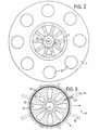
- Fig. 2 die Draufsicht 11-11 des Grilltisches nach Fig. 1 und
- Fig. 3 einen Horizontalschnitt 111-111.
- 1 is a vertical section of a grill table,
- Fig. 2 is a plan view 11-11 of the grill table of Fig. 1 and
- Fig. 3 is a horizontal section 111-111.
Der dargestellte Gtilltisch hat eine kreisrunde Tischplatte 1, die mittig über mehrere Abstandshalter 2 von einem zylindrischen Hohlfuß 3 abgestützt ist. Infolge der Abstandshalter 2 befindet sich der obere Rand des Hohlfußes 3 unterhalb der Tischplatte 1, wodurch sich schlitzförmige Lufteintrittsöffnungen 4 ergeben.The table shown has a circular table top 1, which is supported in the middle by a
Die Tischplatte 1 hat eine runde Mittenöffnung, deren Durchmesser nahezu gleich der Innenweite des Hohlfußes 3 ist. In diese Tischplattenöffnung ist ein zylindrischer Feuerungsbehälter 5 eingehängt. Er hat oben einen Flansch, der auf der Tischplatte 1 aufliegt. Der Boden des Feuerungsbehälters 5 hat eine kegelstumpfförmige, nach oben stehende Einformung 6. Zwischen dem Mantel dieser Einformung 6 und dem Mantel des Feuerungsbehälters 5 erstrecken sich zehn sternförmig angeordnete Luftheizrohre 7, die von innen nach außen ansteigen. Die offenen Enden der Luftheizrohre 7 sind in entsprechende Öffnungen der Mantelflächen eingeschweißt und nahezu bündig mit diesen. In den Feuerungsbehälter 5 werden Grillkohlen etwa bis in halber Höhe eingefüllt und entzündet. Zwischen dem Mantel des Feuerungsbehälters 5 und dem Hohlfuß 3 besteht ein ringförmiger Spalt 8.The table top 1 has a round central opening, the diameter of which is almost equal to the inside width of the
Unterhalb des Feuerungsbehälters ist in dem Hohlfuß 3 mittels eines Zwischenringes 9 ein Ventilator 10 eingebaut. Seine Achse verläuft vertikal und er ist von einem Leitrohr 11 umgeben. Der Antriebsmotor ist für Rechts- und Linkslauf vorgesehen.A
In der Nähe seines unteren Endes hat der Hohlfuß 3 über seinen ganzen Umfang regelmäßig verteilte Luftauslaßöffnungen 12. Dieser Lochkranz ist außen von einem Drehring 13 umgeben, der entsprechende Öffnungen aufweist. Durch Verdrehen dieses Drehrings 13 können somit die Luftauslaßöffnungen 12 stufenlos geschlossen und geöffnet werden.In the vicinity of its lower end, the
Wird der Grilltisch im Freien, beispielsweise auf einer Terrasse, aufgestellt, so erfüllt die bisher beschriebene Luftauslaßeinrichtung an sich schon den Bedarf. Es können jedoch zusätzliche Luftströmungskanäle vorgesehen sein, die im folgenden beschrieben werden.If the grill table is set up outdoors, for example on a terrace, the air outlet device described so far in itself fulfills the need. However, additional air flow channels can be provided, which are described below.
Der gezeigte Grilltisch bzw. sein Hohlfuß 3 steht mit seinem unteren Flansch auf einem plattenförmigen Bodenbelag 14 auf. Dieser ist unterstützt von sternförmig angeordneten Trägern 15, insbesondere Profilrohren, die von einem zentral unter dem Hohlfuß 3 angeordneten Nabenring 16 ausgehen, an dem sie befestigt sind. Zwischen den Trägern 15 ergeben sich sektorförmige Luftströmungskanäle 17 (Fig. 3). Mittels eines Drehschiebers läßt sich die Luftströmung vom Inneren des Hohlfußes 3 in die Kanäle 17 ebenfalls stufenlos einstellen.The grill table shown or its
Der Drehschieber besteht aus einer Festplatte 18, welche die ringförmige Durchlaßöffnung zwischen dem Nabenring 16 und dem Rand der Öffnung des Bodenbelages 14 abdeckt. Diese Festplatte 18 hat acht regelmäßig sternförmig angeordnete trapezförmige Fenster 19. Über der Festplatte 18 befindet sich eine Drehplatte 20 gleicher Gestalt, die mittels einer Buchse 21 in dem Nabenring 16 gelagert ist. Mittels eines Griffstücks 22, welches durch einen horizontalen Schlitz des Hohlfußes 3 greift, sind die Drehplatte 20 und der Drehring 13 miteinander verbunden und können gemeinsam zwischen zwei Endstellungen hin und her gedreht werden. Die Anordnung ist vorzugsweise so getroffen, daß in der einen Endstellung der Drehschieber geschlossen und somit die Luftzufuhrzu den Luftströmungskanälen 17 gesperrt ist, während die Luftauslaßöffnungen 12 frei sind. In der anderen Endstellung ist der Drehschieber geöffnet und die Luftauslaßöffnungen 12 sind geschlossen. In den Zwischenstellungen können die Luftströmungen beliebig verteilt werden. Die Luftströmungskanäle 17 können radial so weit vom Grilltisch wegführen, daß die um den Tisch sitzenden Personen von der austretenden Warmluft nicht mehr behelligt werden (Sommerbetrieb). Ist der Grilltisch jedoch von einem kleinen Aufenthaltsraum umbaut, so können die Luftströmungskanäle 17 wahlweise im Rückenbereich der Personen, aber innerhalb des Gebäudes durch den Bodenbelag 14 wieder nach oben geführt werden.The rotary valve consists of a
Die kupferpe Tischplatte 1 hat acht muldenartige Vertiefungen 23, die vorzugsweise in gleichen Umfangsabständen angeordnet sind. Diese muldenartigen Vertiefungen sind entweder mit einer Zinnauflage versehen, so daß sie unmittelbar als Eßmulden verwendet werden können, oder es sind in diese Vertiefungen passende Metallteller vorgesehen.The copper table top 1 has eight trough-
Am oberen Ende der Einformung 6 des Feuerungsbehälters ist ein vertikal stehender Tragstab 24 befestigt. An ihm ist eine Schiebehülse 25 verschiebbar geführt, welche an ihrem unteren Ende einen runden Grillrost 26 trägt. Der Außendurchmesser dieses Grillrosts ist etwas kleiner als der Innendurchmesser des Feuerungsbehälters 5. Oberhalb des Grillrosts ist eine Aufnahmeschale 27 an der Schiebehülse 25 befestigt. Sie dient zur Vorratshaltung für das zu grillende Gut. Am oberen Ende der Schiebehülse 25 ist eine Arretiervorrichtung 28 vorgesehen, die einen Rastbolzen enthält. Dieser greift in eine von einer größeren Anzahl von Umfangsrillen des Tragstabes 24 ein, die in verschiedenen Höhen angeordnet sind. Dadurch läßt sich die Höhe des Grillrosts 26 je nach der augenblicklichen Hitze der Glut beliebig einstellen, wobei jedoch der Grillrost und die Aufnahmeschale drehbar bleiben.A vertically standing
Der beschriebene Grilltisch wirkt wie folgt : Wenn sich nach dem Entzünden der Grillkohlen der Feuerungsbehälter 5 langsam erwärmt, die Tischplatte 1 jedoch noch kalt ist, kann man durch eine kurzzeitige Inbetriebnahme des Ventilators 10 mit Förderrichtung nach oben (entgegen den dargestellten Pfeilen) die Tischplatte schnell erwärmen. Die Luft wird dabei durch die Luftauslaßöffnungen 12 angesaugt und durch die Luftheizrohre bzw. den Spalt 8 gedrängt, so daß heiße Luft an den Lufteintrittsöffnungen 4 austritt und an der Unterseite der Tischplatte entlangströmt.The grill table described works as follows: If the firing
Nach dieser kurzen Anwärmphase wird die Drehrichtung des Ventilators 10 gewechselt. Die Luftströmung verläuft nunmehr nach den in Fig. 1 eingezeichneten Pfeilen. Die kalte Luft wird unter der Tischplatte 1 angesaugt und kühlt dadurch diese Platte. Nach Passieren der Lufteintrittsöffnungen 4 erwärmt sich die Luft im Spalt 8 und in den Luftheizrohren 7 und strömt weiter nach unten, wo sie je nach Einstellung des Griffstücks 22 entweder durch die Luftauslaßöffnungen 12 oder durch die Luftströmungskanäle 17 (Fig. 3) oder auf beiden Wegen, ggf. in unterschiedlichem Mengenverhältnis, austritt.
- 1 Tischplatte
- 2 Abstandshalter
- 3 Hohlfuß
- 4 Lufteintrittsöffnung
- 5 Feuerungsbehälter
- 6 Einformung
- 7 Luftheizrohr
- 8 Spalt
- 9 Zwischenring
- 10 Ventilator
- 11 Leitrohr
- 12 Luftauslaßöftnung
- 13 Drehring
- 14 Bodenbelag
- 15 Träger
- 16 Nabenring
- 17 Luftströmungskanal
- 18 Festplatte
- 19 Fenster
- 20 Drehplatte
- 21 Buchse
- 22 Griffstück
- 23 Vertiefung
- 24 Tragstab
- 25 Schiebehülse
- 26 Grillrost
- 27 Aufnahmeschale
- 28 Arretiervorrichtung
- 1 table top
- 2 spacers
- 3 hollow foot
- 4 air inlet opening
- 5 firing containers
- 6 molding
- 7 air heating pipe
- 8 gap
- 9 intermediate ring
- 10 fan
- 11 guide tube
- 12 air outlet opening
- 13 rotating ring
- 14 flooring
- 15 carriers
- 16 hub ring
- 17 air flow duct
- 18 hard drive
- 19 windows
- 20 turntable
- 21 socket
- 22 handle
- 23 deepening
- 24 support rod
- 25 sliding sleeve
- 26 grillage
- 27 receiving tray
- 28 locking device
Claims (6)
Priority Applications (1)
| Application Number | Priority Date | Filing Date | Title |
|---|---|---|---|
| AT85113910T ATE32423T1 (en) | 1984-11-24 | 1985-10-31 | BBQ TABLE. |
Applications Claiming Priority (2)
| Application Number | Priority Date | Filing Date | Title |
|---|---|---|---|
| DE3442971 | 1984-11-24 | ||
| DE3442971 | 1984-11-24 |
Publications (2)
| Publication Number | Publication Date |
|---|---|
| EP0183082A1 EP0183082A1 (en) | 1986-06-04 |
| EP0183082B1 true EP0183082B1 (en) | 1988-02-10 |
Family
ID=6251112
Family Applications (1)
| Application Number | Title | Priority Date | Filing Date |
|---|---|---|---|
| EP85113910A Expired EP0183082B1 (en) | 1984-11-24 | 1985-10-31 | Grilling table |
Country Status (3)
| Country | Link |
|---|---|
| EP (1) | EP0183082B1 (en) |
| AT (1) | ATE32423T1 (en) |
| DE (1) | DE3561575D1 (en) |
Families Citing this family (8)
| Publication number | Priority date | Publication date | Assignee | Title |
|---|---|---|---|---|
| DE4326837A1 (en) * | 1993-08-10 | 1995-02-16 | Paul Schacht | Suction device |
| AUPM662194A0 (en) * | 1994-07-05 | 1994-07-28 | Cantrill, Ronald Owen | The original warm B.B.Q table |
| DE202009015435U1 (en) * | 2009-11-12 | 2011-03-24 | Schmidt, Daniel | Outdoor warming device Outdoor heated bistro table for the catering and home sectors |
| DE202010017123U1 (en) * | 2010-12-28 | 2012-04-02 | Staedtler + Uhl Kg | Heated table |
| US20120210994A1 (en) * | 2011-02-23 | 2012-08-23 | Mike Peter Gulotta | Apparatus and method for heat distribution from gas fire |
| MX2016002463A (en) * | 2013-08-29 | 2016-06-24 | Brand Developers Aust Pty Ltd | Grilling apparatus. |
| KR101900223B1 (en) | 2018-06-25 | 2018-09-18 | 문성현 | Barbecue table |
| FR3123417B3 (en) * | 2021-05-31 | 2023-10-06 | Confort Domo France | Brazier table |
Family Cites Families (10)
| Publication number | Priority date | Publication date | Assignee | Title |
|---|---|---|---|---|
| DE7702274U1 (en) * | Kleine, Peter, 4619 Bergkamen-Ruenthe | |||
| FR726200A (en) * | 1930-11-15 | 1932-05-24 | Forced hot air stove for rapid space heating | |
| US2058254A (en) * | 1934-09-10 | 1936-10-20 | Paul C Pederson | Heating appliance |
| FR1003548A (en) * | 1947-01-21 | 1952-03-19 | Essor Economique | Improvements in means for heating premises, in particular for housing, in particular for heating prefabricated premises of this type |
| US2742892A (en) * | 1953-08-04 | 1956-04-24 | Gen Machine Company Inc | Fireplace heater unit |
| US3327697A (en) * | 1965-09-24 | 1967-06-27 | Berlant Sigmund | Cooking device provided with air curtain |
| FR1570591A (en) * | 1968-03-22 | 1969-06-13 | ||
| DE7404217U (en) * | 1974-02-07 | 1974-05-02 | Streicher M | Grill table |
| FR2288504A1 (en) * | 1975-06-11 | 1976-05-21 | Selva Guy | Barbecue for open air cooking - has removable fire box inside concrete pedestal with base in permanent position |
| US4481408A (en) * | 1983-11-07 | 1984-11-06 | Scheufler John H | Cooking apparatus |
-
1985
- 1985-10-31 DE DE8585113910T patent/DE3561575D1/en not_active Expired
- 1985-10-31 EP EP85113910A patent/EP0183082B1/en not_active Expired
- 1985-10-31 AT AT85113910T patent/ATE32423T1/en not_active IP Right Cessation
Also Published As
| Publication number | Publication date |
|---|---|
| DE3561575D1 (en) | 1988-03-17 |
| ATE32423T1 (en) | 1988-02-15 |
| EP0183082A1 (en) | 1986-06-04 |
Similar Documents
| Publication | Publication Date | Title |
|---|---|---|
| DE2700332A1 (en) | OVEN WITH RADIATION OR CONVECTION OPERATION AND STOVE WITH SUCH OVEN | |
| DE2519998A1 (en) | TRANSPORTABLE HEATING DEVICE | |
| EP0183082B1 (en) | Grilling table | |
| DE4136048A1 (en) | FURNACE OVEN | |
| DE202016002911U1 (en) | Additional arrangement for a pan-type cooking appliance | |
| EP0065944A1 (en) | Tiled stove | |
| DE3824413A1 (en) | Device for the heat treatment of foodstuffs | |
| AT15072U1 (en) | Grill facility | |
| DE8434535U1 (en) | Grill table | |
| DE2331270C2 (en) | Stove with interchangeable cooking units | |
| EP1233693B1 (en) | Combined portable gas range | |
| EP1183976B1 (en) | Grilling device | |
| DE2704421C2 (en) | Barbecue device that can be used as a smoking device | |
| DE1915359C (en) | ||
| DE3928730A1 (en) | Grill for use with gas cooker - consists of base with grid and cover set on top of burner | |
| DE2947476C2 (en) | Fireplaces for solid fuels, in particular wood | |
| DE202005013606U1 (en) | Mobile fireplace e.g. chimney for e.g. building, has mantel surrounding fuel container and burner along closed horizontal circumferential line in flame-proof manner in firing operation, and made from transparent material to predominant part | |
| AT201740B (en) | Electric cooker and heater | |
| AT202741B (en) | Countertop stove or heater | |
| DE2638748A1 (en) | Weather-resistant concrete barbecue - comprises sub-units each cast with table top and support leg portions | |
| DE202022104895U1 (en) | Oven with adjustable air damper | |
| CH205466A (en) | Electric heater. | |
| CH192330A (en) | Stove. | |
| DE3020360C2 (en) | Fireplace insert | |
| DE202019103389U1 (en) | Attachment for a heat source, kit with a heat source and such an attachment and use of such an attachment |
Legal Events
| Date | Code | Title | Description |
|---|---|---|---|
| PUAI | Public reference made under article 153(3) epc to a published international application that has entered the european phase |
Free format text: ORIGINAL CODE: 0009012 |
|
| AK | Designated contracting states |
Kind code of ref document: A1 Designated state(s): AT BE CH DE FR GB IT LI LU NL SE |
|
| 17P | Request for examination filed |
Effective date: 19860628 |
|
| 17Q | First examination report despatched |
Effective date: 19870123 |
|
| GRAA | (expected) grant |
Free format text: ORIGINAL CODE: 0009210 |
|
| AK | Designated contracting states |
Kind code of ref document: B1 Designated state(s): AT BE CH DE FR GB IT LI LU NL SE |
|
| PG25 | Lapsed in a contracting state [announced via postgrant information from national office to epo] |
Ref country code: NL Effective date: 19880210 Ref country code: IT Free format text: LAPSE BECAUSE OF FAILURE TO SUBMIT A TRANSLATION OF THE DESCRIPTION OR TO PAY THE FEE WITHIN THE PRESCRIBED TIME-LIMIT;WARNING: LAPSES OF ITALIAN PATENTS WITH EFFECTIVE DATE BEFORE 2007 MAY HAVE OCCURRED AT ANY TIME BEFORE 2007. THE CORRECT EFFECTIVE DATE MAY BE DIFFERENT FROM THE ONE RECORDED. Effective date: 19880210 Ref country code: FR Free format text: THE PATENT HAS BEEN ANNULLED BY A DECISION OF A NATIONAL AUTHORITY Effective date: 19880210 Ref country code: BE Effective date: 19880210 |
|
| REF | Corresponds to: |
Ref document number: 32423 Country of ref document: AT Date of ref document: 19880215 Kind code of ref document: T |
|
| PG25 | Lapsed in a contracting state [announced via postgrant information from national office to epo] |
Ref country code: SE Effective date: 19880229 |
|
| REF | Corresponds to: |
Ref document number: 3561575 Country of ref document: DE Date of ref document: 19880317 |
|
| EN | Fr: translation not filed | ||
| NLV1 | Nl: lapsed or annulled due to failure to fulfill the requirements of art. 29p and 29m of the patents act | ||
| GBV | Gb: ep patent (uk) treated as always having been void in accordance with gb section 77(7)/1977 [no translation filed] | ||
| PG25 | Lapsed in a contracting state [announced via postgrant information from national office to epo] |
Ref country code: LU Free format text: LAPSE BECAUSE OF NON-PAYMENT OF DUE FEES Effective date: 19881031 |
|
| PG25 | Lapsed in a contracting state [announced via postgrant information from national office to epo] |
Ref country code: GB Free format text: LAPSE BECAUSE OF NON-PAYMENT OF DUE FEES Effective date: 19881124 |
|
| PLBE | No opposition filed within time limit |
Free format text: ORIGINAL CODE: 0009261 |
|
| STAA | Information on the status of an ep patent application or granted ep patent |
Free format text: STATUS: NO OPPOSITION FILED WITHIN TIME LIMIT |
|
| 26N | No opposition filed | ||
| PGFP | Annual fee paid to national office [announced via postgrant information from national office to epo] |
Ref country code: DE Payment date: 19891002 Year of fee payment: 5 |
|
| PGFP | Annual fee paid to national office [announced via postgrant information from national office to epo] |
Ref country code: AT Payment date: 19891013 Year of fee payment: 5 |
|
| PGFP | Annual fee paid to national office [announced via postgrant information from national office to epo] |
Ref country code: CH Payment date: 19891228 Year of fee payment: 5 |
|
| PG25 | Lapsed in a contracting state [announced via postgrant information from national office to epo] |
Ref country code: LI Effective date: 19901031 Ref country code: CH Effective date: 19901031 Ref country code: AT Effective date: 19901031 |
|
| REG | Reference to a national code |
Ref country code: CH Ref legal event code: PL |
|
| PG25 | Lapsed in a contracting state [announced via postgrant information from national office to epo] |
Ref country code: DE Effective date: 19910702 |