EP0181532A1 - Procédé pour la connexion d'éléments de la technique de la communication optique les uns avec les autres ou avec des éléments de connecteurs démontables - Google Patents
Procédé pour la connexion d'éléments de la technique de la communication optique les uns avec les autres ou avec des éléments de connecteurs démontables Download PDFInfo
- Publication number
- EP0181532A1 EP0181532A1 EP85113345A EP85113345A EP0181532A1 EP 0181532 A1 EP0181532 A1 EP 0181532A1 EP 85113345 A EP85113345 A EP 85113345A EP 85113345 A EP85113345 A EP 85113345A EP 0181532 A1 EP0181532 A1 EP 0181532A1
- Authority
- EP
- European Patent Office
- Prior art keywords
- coupling
- adjustment
- welding
- another
- adjusting
- Prior art date
- Legal status (The legal status is an assumption and is not a legal conclusion. Google has not performed a legal analysis and makes no representation as to the accuracy of the status listed.)
- Granted
Links
Images


Classifications
-
- G—PHYSICS
- G02—OPTICS
- G02B—OPTICAL ELEMENTS, SYSTEMS OR APPARATUS
- G02B6/00—Light guides; Structural details of arrangements comprising light guides and other optical elements, e.g. couplings
- G02B6/24—Coupling light guides
- G02B6/42—Coupling light guides with opto-electronic elements
- G02B6/4201—Packages, e.g. shape, construction, internal or external details
- G02B6/4219—Mechanical fixtures for holding or positioning the elements relative to each other in the couplings; Alignment methods for the elements, e.g. measuring or observing methods especially used therefor
- G02B6/4236—Fixing or mounting methods of the aligned elements
- G02B6/4237—Welding
-
- G—PHYSICS
- G02—OPTICS
- G02B—OPTICAL ELEMENTS, SYSTEMS OR APPARATUS
- G02B6/00—Light guides; Structural details of arrangements comprising light guides and other optical elements, e.g. couplings
- G02B6/24—Coupling light guides
- G02B6/36—Mechanical coupling means
- G02B6/38—Mechanical coupling means having fibre to fibre mating means
- G02B6/3807—Dismountable connectors, i.e. comprising plugs
- G02B6/381—Dismountable connectors, i.e. comprising plugs of the ferrule type, e.g. fibre ends embedded in ferrules, connecting a pair of fibres
- G02B6/3825—Dismountable connectors, i.e. comprising plugs of the ferrule type, e.g. fibre ends embedded in ferrules, connecting a pair of fibres with an intermediate part, e.g. adapter, receptacle, linking two plugs
-
- G—PHYSICS
- G02—OPTICS
- G02B—OPTICAL ELEMENTS, SYSTEMS OR APPARATUS
- G02B6/00—Light guides; Structural details of arrangements comprising light guides and other optical elements, e.g. couplings
- G02B6/24—Coupling light guides
- G02B6/42—Coupling light guides with opto-electronic elements
- G02B6/4201—Packages, e.g. shape, construction, internal or external details
- G02B6/4202—Packages, e.g. shape, construction, internal or external details for coupling an active element with fibres without intermediate optical elements, e.g. fibres with plane ends, fibres with shaped ends, bundles
-
- G—PHYSICS
- G02—OPTICS
- G02B—OPTICAL ELEMENTS, SYSTEMS OR APPARATUS
- G02B6/00—Light guides; Structural details of arrangements comprising light guides and other optical elements, e.g. couplings
- G02B6/24—Coupling light guides
- G02B6/36—Mechanical coupling means
- G02B6/38—Mechanical coupling means having fibre to fibre mating means
- G02B6/3807—Dismountable connectors, i.e. comprising plugs
- G02B6/3833—Details of mounting fibres in ferrules; Assembly methods; Manufacture
- G02B6/3855—Details of mounting fibres in ferrules; Assembly methods; Manufacture characterised by the method of anchoring or fixing the fibre within the ferrule
Definitions
- the invention relates to a method for connecting elements of optical communications technology to one another or with elements of detachable plug connections according to the preamble of claim 1, a plug part for detachable plug connections of optical fibers according to the preamble of claim 13 and an optical transmitter module according to the preamble of claim 14.
- a desired coupling position In the manufacture of optical transmitter modules, a desired coupling position must be established between a laser diode and the coupling optics associated with an optical waveguide, which coupling position ensures optimal transmission of the light emitted by the laser diode into the optical waveguide. Also in the manufacture of plug parts for detachable plug connections of optical fibers, a coupling position must be established between a plug-in cylinder and an optical fiber, which ensures that the core of the optical fiber is exactly centered on the outer circumference of the plug-in cylinder and thus only minimal coupling losses occur in the finished plug-in connection.
- the setting of the desired coupling position requires dimensional accuracies which are in the submicron range, the adjusted coupling position having to remain stable during the connection of the respective elements and thereafter.
- the fixed coupling position requires a time stability with guide values in the range of 10 5 hours and a climate resistance, their guide values with 70% relative humidity at a temperature of 40 ° C and with temperature changes between -25 ° C and 75 ° C can be specified.
- adhesive methods and soldering methods are used, but with which the requirements made can only be met to a limited extent.
- Adhesives have the disadvantage that they shrink considerably, have large coefficients of thermal expansion and are also very sensitive to moisture and heat. Soldered connections, which lead to a high thermal load on the elements to be connected, also tend to creep easily under mechanical stresses.
- DE-A-2 704 140 discloses a method for producing plug parts for detachable plug connections of optical fibers, in which the optical fibers are first fastened in a central bore in a hollow cylindrical adjusting body.
- This adjusting body is provided with a likewise cylindrical collar, the rear circular surface of which forms a coupling surface set back relative to the front end of the optical fiber.
- This coupling surface is assigned a second coupling surface, which is formed by an end face of a hollow cylindrical plug-in cylinder.
- the adjustment body is then inserted into the plug-in cylinder in such a way that the two coupling surfaces abut one another and both parts can be displaced relative to one another until the desired adjustment position is reached in which the core of the optical fiber is precisely centered on the outer circumference of the plug-in cylinder.
- the adjustment body is then fixed in the plug-in cylinder, this fixing being carried out, for example, by gluing, soldering or welding.
- two plug parts produced in this way are then inserted into a common sleeve and pressed together until the end faces of the optical fibers abut each other.
- the fixation of a set adjustment position by laser beam welding has the advantage that the heat load on the parts to be connected is low and that the fixation is time-stable and climate-resistant. On the other hand, however, a welding delay occurs during the welding process, which prevents fixation with dimensional accuracy in the submicrometer range.
- the invention has for its object to provide a method for connecting elements of optical communication technology with one another or with elements of detachable plug connections, in which the elements to be connected are adjusted relative to each other with dimensional accuracy in the submicrometer range and permanently in the adjustment position reached, ie fixed in a time-stable and climate-resistant manner.
- the method should be able to be used in particular in the production of optical transmitter modules and in the production of plug parts for detachable plug connections of optical fibers.
- the elements to be fixed or connected to one another such as laser diodes and coupling optics or optical fibers and plug-in cylinders, are thus first attached to weldable adjustment bodies, which are connected to one another by at least one welding point after a desired adjustment position has been reached.
- the welding spot is set by means of a laser beam or electron beam, so that only extremely small areas of the adjusting body are briefly heated and the heat distortion is accordingly extremely low. Since the coupling surfaces of the adjustment bodies lie against one another without play, the adjustment bodies can be brought into an exact adjustment position and fixed in this position, similar to when stacking gauge blocks.
- the first welding point is set such that a distance remains between the melting zone and a circle circumscribing the coupling surface contour.
- the welding point is thus set so that the melting zone does not touch or touch the circle circumscribing the coupling surface contour.
- At least the two first welding points are set such that a distance remains between the melting zone and a circle circumscribing the coupling surface contour. This further reduces the risk of welding delay due to the need for additional welding points or weld seams.
- the welding points are preferably placed in flat areas of the coupling surface contour.
- Adjustment bodies with flat coupling surfaces can be used in the method according to the invention. However, it is particularly advantageous if adjustment bodies are used in which at least one coupling surface has a concave shape. This further reduces the risk of welding distortion, since the coupling surfaces are pressed against one another when the melting zones cool without changing their position.
- the other coupling surface can have a flat surface.
- the other coupling surface can then also have a convex surface, but the concave surface must be more curved than the convex surface.
- the radii of curvature of the coupling surfaces are dimensioned larger than the diameter of the circle circumscribing the coupling surface, the difference being several orders of magnitude. This dimensioning means that the maximum width of the part joint is extremely small and is, for example, about 2 pm.
- adjustment bodies are used whose coupling surface contours have different, in particular opposite, inclinations, at least in the region of the first two welding points.
- the dimensional accuracies achieved during adjustment can be increased even further if the adjustment bodies are pressed against one another with a force acting perpendicular to the coupling surfaces.
- the adjustment bodies are then expediently displaced relative to one another in small increments of at most 0.01 ⁇ m until the adjustment position is reached.
- a first variant of the idea on which the method according to the invention is based relates to a plug part for detachable plug connections of optical waveguides, with a plug cylinder in which an optical fiber, in particular a single-mode fiber, is centrally fixed.
- the object on which the invention is based is achieved here by the characterizing features of claim 13.
- the adjusting bodies can thus be displaced relative to one another with coupling surfaces lying against one another without play until the optical fiber is aligned exactly centrally to the outer circumference of the plug-in cylinder in the desired adjusting position and this position is then fixed by at least one welding point. This time-stable and climate-resistant fixation can minimize the coupling losses of the finished plug connection.
- a second variant of the idea on which the method according to the invention is based relates to an optical transmitter module with a laser diode, coupling optics and an optical waveguide, the optical axis of the coupling optics being aligned relative to the optical axis of the laser diode in a predeterminable adjustment position.
- the object on which the invention is based is achieved in such an optical transmitter module by the characterizing features of claim 14.
- the adjustment bodies can be displaced relative to one another with coupling surfaces lying against one another without play until the laser diode and the coupling optics are aligned with one another in the exact adjustment position and this position is fixed by at least one welding point.
- the coupling optics and the optical waveguide are fixed in a tubular fiber carrier and the fiber carrier is fastened in a longitudinal guide of the first adjusting body.
- a desired distance between the coupling optics and the laser diode can then first be adjusted by moving the fiber carrier in the longitudinal guide, whereupon the fiber carrier is fixed in the first adjusting body and only then the other adjustments and fixings are carried out.
- the elements to be connected are first attached to weldable adjustment bodies, whereupon the adjustment bodies are displaced relative to one another with coupling surfaces lying against one another without play until a desired adjustment position is reached.
- the adjusting bodies are then connected to one another in the region of the part joint formed by the coupling surfaces by means of laser beam welding by means of welding spots.
- the welding spots could also be produced by electron beam welding, but the connection would then have to be made in a vacuum. Since only small areas of the adjustment bodies are briefly heated in both laser beam welding and electron beam welding, the heat distortion is also very low.
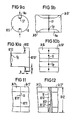
- FIGS. 1 to 9 show exemplary embodiments for suitable coupling surface profiles, the part joint in each case being denoted by Tf, the welding points in each case by Sp and the circles circumscribing the coupling surface contours each by K. It can be seen that all the welding points Sp are set such that there is always a certain distance between the melting zone and the circle K circumscribing the coupling surface contour. The melting zones of the welding points Sp therefore do not touch the circle K in any case. The position of the welding points Sp also depends on the existing symmetry of the coupling surface contours. In FIGS.
- Figures la and lb show adjustment body Jkl and Jkl ', the coupling surfaces Kfl are each T-shaped.
- the two adjustment bodies Jkl and Jkl ' are connected by a total of four welding spots Sp set in the area of the part joint Tf.
- Two welding spots Sp are located on the underside of the T-shaped projection, while the other two welding spots Sp lie in the area of the base of the T-profile.
- FIGS. 2a and 2b show adjustment bodies Jk2 and Jk2 ', the coupling surfaces Kf2 of which are each U-shaped.
- the two adjustment bodies Jk2 and Jk2 ' are connected by a total of four welding points Sp set in the area of the part joint Tf.
- a welding point Sp is located on each end face of the legs of the U-profile, while the other two welding points Sp are located in the area of the groove base of the U- Profiles lie.
- FIGS. 3a and 3b show adjustment bodies Jk3 and Jk3 ', the coupling surfaces Kf3 of which are each V-shaped.
- the two adjustment bodies Jk3 and Jk3 ' are connected by a total of three welding points Sp set in the area of the part joint Tf.
- FIGS. 4a and 4b show adjustment bodies Jk4 and Jk4 ', the coupling surfaces Kf4 of which are each L-shaped.
- the two adjustment bodies Jk4 and Jk4 ' are connected by a total of three welding points Sp set in the area of the part joint Tf.
- FIGS. 5a and 5b show adjustment bodies Jk5 and Jk5 ', the coupling surfaces Kf5 of which are each machined out of an annular cross section.
- the connection of the two Adjusting bodies Jk5 and Jk5 ' are made by a total of three welding points Sp set in the area of the part joint Tf.
- the coupling surface Kf4 consisting of two surface areas each highlighted by hatching, was worked out from the circular cross-section in such a way that a distance remains between the melting zones of the welding points Sp and the circumscribing circle K.
- FIGS. 6a and 6b show adjustment bodies Jk6 and Jk6 ', the coupling surfaces Kf6 of which are each square.
- the two adjusting bodies Jk6 and Jk6 ' are connected by a total of four welding points Sp set in the area of the part joint Tf.
- a welding point Sp is located in the middle of each side of the square profile.
- FIGS. 7a and 7b show adjustment bodies Jk7 and Jk7 ', the coupling surfaces Kf7 of which are each U-shaped.
- the two adjustment bodies Jk7 and Jk7 ' are connected by a total of four welding spots Sp set in the area of the part joint Tf.
- FIGS. 8a and 8b show adjustment bodies Jk8 and Jk8 ', the coupling surfaces Kf8 of which are each V-shaped.
- the two adjustment bodies Jk8 and Jk8 ' are connected by a total of four welding points Sp set in the area of the part joint Tf.
- FIGS. 9a and 9b show adjustment bodies, Jk9 and Jk9 1 , the coupling surfaces Kf9 of which are each circular, the circle K circumscribing the coupling surfaces Kf9 being formed by the outer circumference.
- U-shaped grooves Nu are introduced into the adjusting bodies Jk9 and Jk9 'in the longitudinal direction.
- the two adjustment bodies Jk9 and Jk9 ' are connected by a total of two welding points Sp set in the area of the part joint Tf. There is a welding point Sp on each groove base of the grooves Nu.
- FIGS. 10a and 10b show adjustment bodies Jk10 and JklO ', the coupling surfaces KflO and Kf10' of which are designed such that displacements caused by the adjustment process cannot lead to welding steps.
- the basic shape of the T-shaped profiles of the coupling surfaces KflO and KflO ' are modified so that there are opposing inclinations on the underside of the T-shaped projection and at two points in the area of the base of the T-profile.
- the total of four welding points S p provided in the area of the part joint Tf can then also be set at the crossing point of the opposite inclinations even after a displacement in the area of the adjustment paths Jx and Jy, ie no welding steps occur.
- the coupling surfaces of the adjustment bodies must lie against one another without play during the adjustment process. According to FIG. 11, this can be achieved, for example, in that two adjusting bodies Jkll and Jkll 'to be connected to one another lie against one another with flat coupling surfaces Kfll and Kfll'.
- the coupling surfaces Kfll and Kfll l should be machined so finely that no gaps occur in the peripheral area of the part joint Tf. For an absolutely play-free application of the coupling surfaces, however, it is more favorable if at least one coupling surface has a concave shape.
- pairings are possible in which the one adjusting body Jk12 has a flat coupling surface Kf12, while the other adjusting body Jk12 'has a concavely curved coupling surface Kfl2'.
- the adjusting bodies Jk12 and Jk12 'then lie against one another only in the peripheral region of the coupling surfaces Kf12 and Kfl2'. If R12 denotes the radius of the concave curvature and 012 the diameter of the circle circumscribing the coupling surfaces Kfl2 and Kfl2 ', then D12 ⁇ R12 must be. This means that the maximum width of the part joint Tf is extremely small and in reality, for example, is only about 2 ⁇ m.
- pairings are also possible in which two adjusting bodies Jk13 and Jk13 'each have concavely curved coupling surfaces Kf13 and Kfl3'.
- the adjusting bodies Jk13 and Jk13 1 then also abut one another only in the peripheral region of the coupling surfaces Kfl3 and Kfl3 '.
- R13 denotes the radius of the concave curvature of the coupling surface Kfl3
- R13 ' the radius of the concave curvature of the coupling surface Kf13' and D13 the diameter of the circle circumscribing the coupling surfaces Kf13 and Kf13 '
- D13 ⁇ R13 and D13 ⁇ R13 ' This means that the maximum width of the part joint Tf is also extremely small here and is, for example, only about 2 ⁇ m.
- pairings are also possible in which the one adjusting body Jkl4 has a convex coupling surface Kf14, while the other adjusting body Jk14 'has a concavely curved coupling surface Kfl4'.
- R14 denotes the radius of the convex curvature of the coupling surface Kfl4
- R14' ⁇ R14, D14 ⁇ R14 and D14 ⁇ R14 ' the diameter of the circle circumscribing the coupling surfaces Kf14 and Kf14 '
- FIGS. 15 to 18 show, in a highly simplified schematic representation, different process stages in the manufacture of a plug part for detachable plug connections of optical fibers. It is apparent from FIG. 15 that an optical fiber Lf which has been freed from its sheath H in the end region is fastened in a central bore in a first adjusting body Jk15, this fastening being able to be carried out, for example, with the aid of a thin adhesive layer.
- the first adjustment body Jkl5 is designed in such a way that a coupling surface Kfl5, which is set back with respect to the front end of the optical fiber Lf, is produced.
- This coupling surface Kfl5 is assigned the coupling surface Kf15 'of a second adjusting body Jk15', which is fastened according to FIG. 16 in a hollow cylindrical plug-in cylinder Sz.
- the coupling surface Kfl5 of the ring-shaped second adjustment body Jk15 ' is subjected to a fine machining before the second adjustment body Jk15' is fastened in the plug-in cylinder Sz, for example by laser beam welding.
- the first adjusting body Jk15 is then inserted into the plug-in cylinder Sz such that the coupling surfaces Kfl5 and Kfl5 'abut one another.
- the dimensions are chosen such that a radial play remains between the coupling surface contour of the first adjusting body Jk15 and the inner circumference of the plug-in cylinder Sz and also between the cylindrical extension A of the first adjusting body Jk15 and the inner bore of the second adjusting body Jk15 '.
- the adjusting bodies Jk15 and Jk15 ' are then pressed together with a small force acting perpendicular to the coupling surfaces Kfl5 or Kf15' and shifted relative to one another in small increments of at most 0.01 ⁇ m until the desired adjustment position is reached, in which the core of the optical fiber Lf exactly centered on the outer circumference of the plug cylinder whose direction is aligned.
- the first adjustment body Jkl5 and the second adjustment body JklS ' are connected to one another in the area of the part joint Tf formed by the coupling surfaces Kfl5 and KflS' according to FIG. 18 by a plurality of welding points Sp.
- the welding spots Sp generated by laser beam welding can be set through corresponding openings 0, which are staggered in uniform division over the circumference of the plug-in cylinder Sz.
- the statements made in connection with FIGS. 1 to 14 apply to the shape of the coupling surfaces Kfl5 and Kfl5 'and the coupling surface contours and to the position of the welding points Sp.
- two of the plug parts produced in accordance with the preceding description are inserted into a common sleeve and pressed together in such a way that the end faces of the optical fibers Lf, previously ground with the end faces of the projections A, abut one another.
- the exact adjustment and fixation ensures that the optical fibers Lf to be coupled are aligned exactly and the coupling losses are minimized accordingly.
- FIG. 19 and 20 show in a highly simplified schematic representation the manufacture of an optical transmitter module.
- an optical waveguide Lwl and a coupling optics Ko are fixed in a tubular fiber carrier Ft.
- the optical waveguide Lwl which has been stripped of its sheathing in the front area, is fixed by gluing in the sheathing, the adhesive layer being denoted by Ks.
- a coupling optic Ko a taper is formed on the front end of the optical waveguide Lwl, the tip of which is rounded off to form a small lens only briefly from the tubular fiber carrier Ft protrudes.
- the optical fiber Lwl is also fixed in a central hole in the fiber carrier Ft by gluing or by soldering or by glazing.
- the second part in the exploded view of FIG. 19 shows a first adjustment body Jkl6, which has a T-shaped cross section.
- a longitudinal guide L for the tubular fiber carrier Ft is introduced into the first adjusting body Jk16, this longitudinal guide L having a stepped U-profile.
- One of the end faces of the adjusting body Jk16 is, for example, so finely machined by lapping that it can serve as a coupling surface Kf16.
- the contour and shape of the coupling surface Kf16 essentially corresponds to the contour and shape of the coupling surface Kfl shown in FIG.
- a third part shows a second adjusting body Jk16 1 , which likewise has a T-shaped cross section in the front area and has a coupling surface Kfl6 1 assigned to the coupling surface Kf16.
- a diode carrier Dt which also serves as a heat sink, is fastened and carries a laser diode denoted by Ld.
- the diode carrier Dt which is attached to the second adjusting body Jkl6, for example by laser beam welding, is adjusted in such a way that the optical axis oA 'of the laser diode Ld is oriented normal to the coupling surface Kf16'.
- a monitor diode carrier Mt is also attached by soldering or gluing, which carries a monitor diode labeled Md.
- the optical transmitter module shown in FIG. 20 can subsequently be inserted into a housing or can already be assembled in a housing.
- adjustment and fixing accuracies of about 2 ⁇ m were sufficient.
- adjustment and fixing accuracies of approximately + 0.1 ⁇ m were achieved.
- FIGS. 21a and 21b show two different views of adjusting bodies Jk17 and Jk17 ', the coupling surfaces Kfl 7 of which are designed such that the connection can be made with the aid of a single welding point Sp.
- an annular groove Rn and a slot-shaped funnel Tr were milled into the circular coupling surfaces Kf17.
- the circle K circumscribing the coupling surfaces Kf17 is formed by the outer circumference.
- the connection of the two adjusting bodies Jkl7 and Jkl7 ' takes place exclusively through the welding point Sp, which is set by means of laser beam welding through the funnel Tr and the annular groove Rn, the welding beam direction being shown in FIG. 21a by an arrow, which is not specified in any more detail.
- the welding point Sp set in the area of the part joint Tf is located on the inner circumference of the annular groove Rn or on the outer circumference of the circular center region of the coupling surface Kfl7.
Landscapes
- Physics & Mathematics (AREA)
- General Physics & Mathematics (AREA)
- Optics & Photonics (AREA)
- Optical Couplings Of Light Guides (AREA)
- Mechanical Coupling Of Light Guides (AREA)
Priority Applications (1)
| Application Number | Priority Date | Filing Date | Title |
|---|---|---|---|
| AT85113345T ATE52623T1 (de) | 1984-10-24 | 1985-10-21 | Verfahren zum verbinden von elementen der optischen nachrichtentechnik miteinander oder mit elementen von loesbaren steckverbindungen. |
Applications Claiming Priority (2)
| Application Number | Priority Date | Filing Date | Title |
|---|---|---|---|
| DE3438940 | 1984-10-24 | ||
| DE3438940 | 1984-10-24 |
Publications (2)
| Publication Number | Publication Date |
|---|---|
| EP0181532A1 true EP0181532A1 (fr) | 1986-05-21 |
| EP0181532B1 EP0181532B1 (fr) | 1990-05-09 |
Family
ID=6248663
Family Applications (1)
| Application Number | Title | Priority Date | Filing Date |
|---|---|---|---|
| EP85113345A Expired - Lifetime EP0181532B1 (fr) | 1984-10-24 | 1985-10-21 | Procédé pour la connexion d'éléments de la technique de la communication optique les uns avec les autres ou avec des éléments de connecteurs démontables |
Country Status (6)
| Country | Link |
|---|---|
| US (1) | US4714315A (fr) |
| EP (1) | EP0181532B1 (fr) |
| JP (1) | JPS61102612A (fr) |
| AT (1) | ATE52623T1 (fr) |
| CA (1) | CA1250903A (fr) |
| DE (1) | DE3577604D1 (fr) |
Cited By (8)
| Publication number | Priority date | Publication date | Assignee | Title |
|---|---|---|---|---|
| EP0304182A2 (fr) * | 1987-08-19 | 1989-02-22 | Nortel Networks Corporation | Transducteur opto-électronique avec un raccord en fibre optique |
| US4826276A (en) * | 1987-07-17 | 1989-05-02 | E. I. Du Pont De Nemours And Company | Optical fiber feedthrough assembly having a rigidizing arrangement therein |
| US5013111A (en) * | 1988-10-20 | 1991-05-07 | Messerschmitt-Boelkow-Blohm Gmbh | Method and device for mounting a laser diode and a light conductor |
| US5177806A (en) * | 1986-12-05 | 1993-01-05 | E. I. Du Pont De Nemours And Company | Optical fiber feedthrough |
| EP0545555A1 (fr) * | 1991-11-07 | 1993-06-09 | AT&T Corp. | Virole pour fibre optique |
| US5222170A (en) * | 1987-04-03 | 1993-06-22 | Bt&D Technologies Ltd. | Optical fiber device fabrication |
| EP0590393A1 (fr) * | 1992-09-26 | 1994-04-06 | Alcatel SEL Aktiengesellschaft | Module à laser semiconducteur |
| EP0286319B1 (fr) * | 1987-04-03 | 1997-12-29 | Hewlett-Packard Limited | Fabrication d'un module à fibre optique |
Families Citing this family (39)
| Publication number | Priority date | Publication date | Assignee | Title |
|---|---|---|---|---|
| FR2546311B1 (fr) * | 1983-05-17 | 1986-03-28 | France Etat | Procede et dispositif de connexion entre une fibre optique et un composant d'optique integree comportant un guide d'onde |
| US4762386A (en) * | 1986-09-02 | 1988-08-09 | Amp Incorporated | Optical fiber assembly including means utilizing a column load to compensate for thermal effects |
| US4747657A (en) * | 1987-06-15 | 1988-05-31 | American Telephone And Telegraph Company | Achieving improved radial alignment in an optical package |
| US4819386A (en) * | 1987-07-20 | 1989-04-11 | Northwestern Bell Corporation | Optic fiber sanding fixture and method of using |
| JPH01118106A (ja) * | 1987-10-30 | 1989-05-10 | Japan Aviation Electron Ind Ltd | 光ファイバ調芯固定方法 |
| US4838639A (en) * | 1987-11-02 | 1989-06-13 | Dukane Corporation | Method and apparatus for orienting a fiber optic member |
| JP2571803B2 (ja) * | 1987-12-11 | 1997-01-16 | 新日本製鐵株式会社 | 光ファイバ入り金属管の接続方法 |
| FR2627868B1 (fr) * | 1988-02-04 | 1993-09-24 | Comp Generale Electricite | Procede de couplage permanent d'une fibre optique a un composant, notamment a un laser semi-conducteur |
| GB8805015D0 (en) * | 1988-03-02 | 1988-03-30 | British Telecomm | Optical fibre locating apparatus |
| US5011256A (en) * | 1988-10-28 | 1991-04-30 | E. I. Du Pont De Nemours And Company | Package for an opto-electronic component |
| US5146522A (en) * | 1989-02-13 | 1992-09-08 | Litton Systems, Inc. | Methods for rugged attachment of fibers to integrated optics chips and product thereof |
| US4976506A (en) * | 1989-02-13 | 1990-12-11 | Pavlath George A | Methods for rugged attachment of fibers to integrated optics chips and product thereof |
| FR2655161B1 (fr) * | 1989-11-30 | 1992-12-24 | Cit Alcatel | Dispositif a double couplage optique, notamment pour systeme de transmission a fibres optiques. |
| US5119462A (en) * | 1990-01-29 | 1992-06-02 | 501 Nippon Sheet Glass Co., Ltd. | Photosemiconductor and optical fiber welded module |
| US5189716A (en) * | 1990-01-29 | 1993-02-23 | Nippon Sheet Glass Co., Ltd. | Photosemiconductor and optical fiber welded module |
| KR0177101B1 (ko) * | 1996-01-25 | 1999-05-15 | 김광호 | 광섬유 접속자 보호 지지대 |
| KR100279755B1 (ko) * | 1998-06-18 | 2001-02-01 | 정선종 | 다채널 광소자 모듈의 광정렬 보정방법 |
| US6198580B1 (en) | 1998-08-17 | 2001-03-06 | Newport Corporation | Gimballed optical mount |
| US6516130B1 (en) | 1998-12-30 | 2003-02-04 | Newport Corporation | Clip that aligns a fiber optic cable with a laser diode within a fiber optic module |
| US6996506B2 (en) | 1999-02-23 | 2006-02-07 | Newport Corporation | Process and device for displacing a moveable unit on a base |
| FR2790115B1 (fr) | 1999-02-23 | 2001-05-04 | Micro Controle | Procede et dispositif pour deplacer un mobile sur une base montee elastiquement par rapport au sol |
| EP1050768A1 (fr) * | 1999-05-05 | 2000-11-08 | Uniphase Corporation | Tête optoélectronique et procédé de fabrication |
| US6142678A (en) * | 1999-06-15 | 2000-11-07 | Jds Uniphase Inc. | Optical coupling |
| US6511035B1 (en) | 1999-08-03 | 2003-01-28 | Newport Corporation | Active vibration isolation systems with nonlinear compensation to account for actuator saturation |
| JP3650591B2 (ja) * | 2000-08-21 | 2005-05-18 | 古河電気工業株式会社 | 光結合モジュールの光軸修正方法 |
| US6655840B2 (en) | 2001-02-13 | 2003-12-02 | Newport Corporation | Stiff cross roller bearing configuration |
| JP2002277676A (ja) * | 2001-03-16 | 2002-09-25 | Nippon Sheet Glass Co Ltd | 光モジュール及びその組み立て方法 |
| US6601524B2 (en) | 2001-03-28 | 2003-08-05 | Newport Corporation | Translation table with a spring biased dovetail bearing |
| US6791058B2 (en) | 2001-04-25 | 2004-09-14 | Newport Corporation | Automatic laser weld machine for assembling photonic components |
| US6568666B2 (en) | 2001-06-13 | 2003-05-27 | Newport Corporation | Method for providing high vertical damping to pneumatic isolators during large amplitude disturbances of isolated payload |
| US6619611B2 (en) | 2001-07-02 | 2003-09-16 | Newport Corporation | Pneumatic vibration isolator utilizing an elastomeric element for isolation and attenuation of horizontal vibration |
| GB0118307D0 (en) * | 2001-07-26 | 2001-09-19 | Gsi Lumonics Ltd | Automated energy beam positioning |
| US6966535B2 (en) | 2002-05-07 | 2005-11-22 | Newport Corporation | Snubber for pneumatically isolated platforms |
| DE10224685A1 (de) * | 2002-06-04 | 2003-12-18 | Bosch Gmbh Robert | Verfahren zur Herstellung von dichtgeschweißten Verbindungen zwischen einem Stanzgitter und einem Kunststoffbauteil |
| US6736550B1 (en) * | 2003-07-31 | 2004-05-18 | Applied Optoelectronics, Inc. | Housing for passively aligning an optical fiber with a lens |
| US7320455B2 (en) | 2003-10-24 | 2008-01-22 | Newport Corporation | Instrumented platform for vibration-sensitive equipment |
| US8231098B2 (en) | 2004-12-07 | 2012-07-31 | Newport Corporation | Methods and devices for active vibration damping of an optical structure |
| US8790483B2 (en) * | 2008-11-24 | 2014-07-29 | Corning Incorporated | Method of weldbonding and a device comprising weldbonded components |
| JP6789187B2 (ja) * | 2017-07-07 | 2020-11-25 | 東京エレクトロン株式会社 | 基板反り検出装置及び基板反り検出方法、並びにこれらを用いた基板処理装置及び基板処理方法 |
Citations (3)
| Publication number | Priority date | Publication date | Assignee | Title |
|---|---|---|---|---|
| US4030811A (en) * | 1975-05-14 | 1977-06-21 | U.S. Philips Corporation | Device for coupling a light source to an optical fiber |
| DE2704140A1 (de) * | 1977-02-02 | 1978-08-03 | Licentia Gmbh | Vorrichtung zum justieren einer lichtleitfaser |
| EP0091738A2 (fr) * | 1982-04-14 | 1983-10-19 | Northern Telecom Limited | Mise en place précise de fibres optiques |
Family Cites Families (6)
| Publication number | Priority date | Publication date | Assignee | Title |
|---|---|---|---|---|
| JPS5946434B2 (ja) * | 1978-01-10 | 1984-11-12 | キヤノン株式会社 | 半導体レ−ザ装置 |
| JPS55155314A (en) * | 1979-05-21 | 1980-12-03 | Nippon Telegr & Teleph Corp <Ntt> | Connecting method of optical fiber and its connector |
| US4500165A (en) * | 1982-04-02 | 1985-02-19 | Codenoll Technology Corporation | Method and apparatus for aligning optical fibers |
| US4615031A (en) * | 1982-07-27 | 1986-09-30 | International Standard Electric Corporation | Injection laser packages |
| US4506108A (en) * | 1983-04-01 | 1985-03-19 | Sperry Corporation | Copper body power hybrid package and method of manufacture |
| US4623220A (en) * | 1984-07-02 | 1986-11-18 | Amp Incorporated | Laser to fiber connection |
-
1985
- 1985-10-15 US US06/787,112 patent/US4714315A/en not_active Expired - Fee Related
- 1985-10-21 DE DE8585113345T patent/DE3577604D1/de not_active Expired - Fee Related
- 1985-10-21 EP EP85113345A patent/EP0181532B1/fr not_active Expired - Lifetime
- 1985-10-21 AT AT85113345T patent/ATE52623T1/de not_active IP Right Cessation
- 1985-10-22 CA CA000493590A patent/CA1250903A/fr not_active Expired
- 1985-10-23 JP JP60237156A patent/JPS61102612A/ja active Pending
Patent Citations (3)
| Publication number | Priority date | Publication date | Assignee | Title |
|---|---|---|---|---|
| US4030811A (en) * | 1975-05-14 | 1977-06-21 | U.S. Philips Corporation | Device for coupling a light source to an optical fiber |
| DE2704140A1 (de) * | 1977-02-02 | 1978-08-03 | Licentia Gmbh | Vorrichtung zum justieren einer lichtleitfaser |
| EP0091738A2 (fr) * | 1982-04-14 | 1983-10-19 | Northern Telecom Limited | Mise en place précise de fibres optiques |
Non-Patent Citations (1)
| Title |
|---|
| PATENTS ABSTRACTS OF JAPAN, Band 6, Nr. 212, 26. Oktober 1982; JP - A - 57 118 212 (NIPPON DENKI K.K.) 23.07.1982 * |
Cited By (12)
| Publication number | Priority date | Publication date | Assignee | Title |
|---|---|---|---|---|
| US5177806A (en) * | 1986-12-05 | 1993-01-05 | E. I. Du Pont De Nemours And Company | Optical fiber feedthrough |
| US5222170A (en) * | 1987-04-03 | 1993-06-22 | Bt&D Technologies Ltd. | Optical fiber device fabrication |
| EP0286319B1 (fr) * | 1987-04-03 | 1997-12-29 | Hewlett-Packard Limited | Fabrication d'un module à fibre optique |
| US4826276A (en) * | 1987-07-17 | 1989-05-02 | E. I. Du Pont De Nemours And Company | Optical fiber feedthrough assembly having a rigidizing arrangement therein |
| EP0304182A2 (fr) * | 1987-08-19 | 1989-02-22 | Nortel Networks Corporation | Transducteur opto-électronique avec un raccord en fibre optique |
| GB2208944A (en) * | 1987-08-19 | 1989-04-19 | Stc Plc | Fibre tailed welded optoelectronic transducer |
| EP0304182A3 (en) * | 1987-08-19 | 1989-11-15 | Stc Plc | Fibre tailed opto-electronic transducer |
| GB2208944B (en) * | 1987-08-19 | 1991-12-18 | Stc Plc | Welded two-part fibre tailed optoelectronic transducer package |
| US5013111A (en) * | 1988-10-20 | 1991-05-07 | Messerschmitt-Boelkow-Blohm Gmbh | Method and device for mounting a laser diode and a light conductor |
| EP0545555A1 (fr) * | 1991-11-07 | 1993-06-09 | AT&T Corp. | Virole pour fibre optique |
| US5649039A (en) * | 1991-11-07 | 1997-07-15 | Lucent Technologies Inc. | Optical fiber ferrule assembly |
| EP0590393A1 (fr) * | 1992-09-26 | 1994-04-06 | Alcatel SEL Aktiengesellschaft | Module à laser semiconducteur |
Also Published As
| Publication number | Publication date |
|---|---|
| ATE52623T1 (de) | 1990-05-15 |
| JPS61102612A (ja) | 1986-05-21 |
| EP0181532B1 (fr) | 1990-05-09 |
| DE3577604D1 (de) | 1990-06-13 |
| US4714315A (en) | 1987-12-22 |
| CA1250903A (fr) | 1989-03-07 |
Similar Documents
| Publication | Publication Date | Title |
|---|---|---|
| EP0181532B1 (fr) | Procédé pour la connexion d'éléments de la technique de la communication optique les uns avec les autres ou avec des éléments de connecteurs démontables | |
| DE60022479T2 (de) | Verfahren zum aufbau einer optoelektronischen anordnung | |
| DE19819164C1 (de) | Baugruppe | |
| DE19610881B4 (de) | Mikrosystembaustein | |
| DE19844701C1 (de) | Verfahren zur Justage eines optoelektronischen Bauelements sowie Bauelement | |
| DE3101378A1 (de) | Optik zur ankopplung eines faseroptischen lichtwellenleiters | |
| DE69933176T2 (de) | Optische Wellenleitervorrichtung und deren Herstellungsverfahren | |
| DE102018106504B4 (de) | Anordnung mit einem TO-Gehäuse, Verfahren zu dessen Herstellung sowie optisches Datenübertragungssystem | |
| DE10305953A1 (de) | Filtermodul (Filter Module) | |
| CA2355800A1 (fr) | Module de multiplexage optique, et methode de correction de l'axe optique cree | |
| EP0178390A2 (fr) | Procédé de couplage des éléments de construction optiques et arrangement pour réaliser le procédé | |
| EP1058139A1 (fr) | Virole pour une fibre optique et procédé pour fixer la virole sur la fibre optique | |
| DE3134508A1 (de) | "optische faser mit einer anamorphotisch abbildenden endflaeche und verfahren zu deren herstellung" | |
| EP1053576B1 (fr) | Procede pour constituer et assembler des composants optiques, notamment les composants optiques d'un resonateur laser et resonateur laser correspondant | |
| DE19927167A1 (de) | Koppelelement zur Kopplung hochintensiver Lichtstrahlung und Verfahren zu dessen Herstellung sowie Anordnung aus Koppelelementen zur Kopplung hochintensiver Lichtstrahlung | |
| DE3407413C2 (fr) | ||
| DE3910166A1 (de) | Optische koppelvorrichtung und verfahren zu deren herstellung | |
| DE19616015C1 (de) | Anordnung zur Ankopplung optischer Sende- oder Empfangselemente an einen Lichtwellenleiter | |
| EP0905534B1 (fr) | Procédé de fixation de l'extrémité d'une fibre optique en verre dans un embout de connexion en verre | |
| DE10204012B4 (de) | Verfahren zum stoffschlüssigen Verbinden mikrotechnischer Bauteile | |
| DE4133220C2 (de) | Fasern-Linsen-Anordnung zum optischen Koppeln | |
| DE3733987A1 (de) | Verfahren und vorrichtung zur herstellung von verbindungsstellen fuer lichtleitfasern an verbindungssteckern | |
| EP0590394A1 (fr) | Dispositif de couplage entre une fibre optique et un module opto-électronique | |
| DE19904445A1 (de) | Linsenstecker zum Aufbau kompakter Freistrahlanordnungen für mehrere Lichtleitfasern | |
| DE3929794A1 (de) | Optisches sendemodul |
Legal Events
| Date | Code | Title | Description |
|---|---|---|---|
| PUAI | Public reference made under article 153(3) epc to a published international application that has entered the european phase |
Free format text: ORIGINAL CODE: 0009012 |
|
| AK | Designated contracting states |
Kind code of ref document: A1 Designated state(s): AT BE CH DE FR GB IT LI NL SE |
|
| 17P | Request for examination filed |
Effective date: 19860606 |
|
| 17Q | First examination report despatched |
Effective date: 19871123 |
|
| GRAA | (expected) grant |
Free format text: ORIGINAL CODE: 0009210 |
|
| AK | Designated contracting states |
Kind code of ref document: B1 Designated state(s): AT BE CH DE FR GB IT LI NL SE |
|
| REF | Corresponds to: |
Ref document number: 52623 Country of ref document: AT Date of ref document: 19900515 Kind code of ref document: T |
|
| REF | Corresponds to: |
Ref document number: 3577604 Country of ref document: DE Date of ref document: 19900613 |
|
| ET | Fr: translation filed | ||
| ITF | It: translation for a ep patent filed |
Owner name: STUDIO JAUMANN |
|
| GBT | Gb: translation of ep patent filed (gb section 77(6)(a)/1977) | ||
| PGFP | Annual fee paid to national office [announced via postgrant information from national office to epo] |
Ref country code: GB Payment date: 19900913 Year of fee payment: 6 |
|
| PGFP | Annual fee paid to national office [announced via postgrant information from national office to epo] |
Ref country code: AT Payment date: 19900928 Year of fee payment: 6 |
|
| PGFP | Annual fee paid to national office [announced via postgrant information from national office to epo] |
Ref country code: BE Payment date: 19901019 Year of fee payment: 6 |
|
| PGFP | Annual fee paid to national office [announced via postgrant information from national office to epo] |
Ref country code: FR Payment date: 19901022 Year of fee payment: 6 |
|
| PGFP | Annual fee paid to national office [announced via postgrant information from national office to epo] |
Ref country code: SE Payment date: 19901024 Year of fee payment: 6 |
|
| ITTA | It: last paid annual fee | ||
| PGFP | Annual fee paid to national office [announced via postgrant information from national office to epo] |
Ref country code: NL Payment date: 19901031 Year of fee payment: 6 |
|
| PGFP | Annual fee paid to national office [announced via postgrant information from national office to epo] |
Ref country code: DE Payment date: 19901221 Year of fee payment: 6 |
|
| PGFP | Annual fee paid to national office [announced via postgrant information from national office to epo] |
Ref country code: CH Payment date: 19910124 Year of fee payment: 6 |
|
| PLBE | No opposition filed within time limit |
Free format text: ORIGINAL CODE: 0009261 |
|
| STAA | Information on the status of an ep patent application or granted ep patent |
Free format text: STATUS: NO OPPOSITION FILED WITHIN TIME LIMIT |
|
| 26N | No opposition filed | ||
| PG25 | Lapsed in a contracting state [announced via postgrant information from national office to epo] |
Ref country code: GB Effective date: 19911021 Ref country code: AT Effective date: 19911021 |
|
| PG25 | Lapsed in a contracting state [announced via postgrant information from national office to epo] |
Ref country code: SE Effective date: 19911022 |
|
| PG25 | Lapsed in a contracting state [announced via postgrant information from national office to epo] |
Ref country code: LI Effective date: 19911031 Ref country code: CH Effective date: 19911031 Ref country code: BE Effective date: 19911031 |
|
| BERE | Be: lapsed |
Owner name: SIEMENS A.G. Effective date: 19911031 |
|
| PG25 | Lapsed in a contracting state [announced via postgrant information from national office to epo] |
Ref country code: NL Effective date: 19920501 |
|
| NLV4 | Nl: lapsed or anulled due to non-payment of the annual fee | ||
| GBPC | Gb: european patent ceased through non-payment of renewal fee | ||
| PG25 | Lapsed in a contracting state [announced via postgrant information from national office to epo] |
Ref country code: FR Effective date: 19920630 |
|
| REG | Reference to a national code |
Ref country code: CH Ref legal event code: PL |
|
| PG25 | Lapsed in a contracting state [announced via postgrant information from national office to epo] |
Ref country code: DE Effective date: 19920701 |
|
| REG | Reference to a national code |
Ref country code: FR Ref legal event code: ST |
|
| EUG | Se: european patent has lapsed |
Ref document number: 85113345.4 Effective date: 19920510 |