EP0178536B1 - Verfahren zum Befestigen von Antriebselementen auf einer zylindrischen Welle mittels azimutal in diese einschneidender Keile, sowie hiernach hergestellte Wellenverbindung - Google Patents
Verfahren zum Befestigen von Antriebselementen auf einer zylindrischen Welle mittels azimutal in diese einschneidender Keile, sowie hiernach hergestellte Wellenverbindung Download PDFInfo
- Publication number
- EP0178536B1 EP0178536B1 EP85112476A EP85112476A EP0178536B1 EP 0178536 B1 EP0178536 B1 EP 0178536B1 EP 85112476 A EP85112476 A EP 85112476A EP 85112476 A EP85112476 A EP 85112476A EP 0178536 B1 EP0178536 B1 EP 0178536B1
- Authority
- EP
- European Patent Office
- Prior art keywords
- keys
- end position
- slot
- drive elements
- contour
- Prior art date
- Legal status (The legal status is an assumption and is not a legal conclusion. Google has not performed a legal analysis and makes no representation as to the accuracy of the status listed.)
- Expired
Links
Images
Classifications
-
- F—MECHANICAL ENGINEERING; LIGHTING; HEATING; WEAPONS; BLASTING
- F16—ENGINEERING ELEMENTS AND UNITS; GENERAL MEASURES FOR PRODUCING AND MAINTAINING EFFECTIVE FUNCTIONING OF MACHINES OR INSTALLATIONS; THERMAL INSULATION IN GENERAL
- F16H—GEARING
- F16H53/00—Cams ; Non-rotary cams; or cam-followers, e.g. rollers for gearing mechanisms
- F16H53/02—Single-track cams for single-revolution cycles; Camshafts with such cams
- F16H53/025—Single-track cams for single-revolution cycles; Camshafts with such cams characterised by their construction, e.g. assembling or manufacturing features
-
- F—MECHANICAL ENGINEERING; LIGHTING; HEATING; WEAPONS; BLASTING
- F01—MACHINES OR ENGINES IN GENERAL; ENGINE PLANTS IN GENERAL; STEAM ENGINES
- F01L—CYCLICALLY OPERATING VALVES FOR MACHINES OR ENGINES
- F01L1/00—Valve-gear or valve arrangements, e.g. lift-valve gear
- F01L1/02—Valve drive
- F01L1/04—Valve drive by means of cams, camshafts, cam discs, eccentrics or the like
- F01L1/047—Camshafts
-
- F—MECHANICAL ENGINEERING; LIGHTING; HEATING; WEAPONS; BLASTING
- F16—ENGINEERING ELEMENTS AND UNITS; GENERAL MEASURES FOR PRODUCING AND MAINTAINING EFFECTIVE FUNCTIONING OF MACHINES OR INSTALLATIONS; THERMAL INSULATION IN GENERAL
- F16D—COUPLINGS FOR TRANSMITTING ROTATION; CLUTCHES; BRAKES
- F16D1/00—Couplings for rigidly connecting two coaxial shafts or other movable machine elements
- F16D1/06—Couplings for rigidly connecting two coaxial shafts or other movable machine elements for attachment of a member on a shaft or on a shaft-end
- F16D1/064—Couplings for rigidly connecting two coaxial shafts or other movable machine elements for attachment of a member on a shaft or on a shaft-end non-disconnectable
- F16D1/072—Couplings for rigidly connecting two coaxial shafts or other movable machine elements for attachment of a member on a shaft or on a shaft-end non-disconnectable involving plastic deformation
-
- F—MECHANICAL ENGINEERING; LIGHTING; HEATING; WEAPONS; BLASTING
- F16—ENGINEERING ELEMENTS AND UNITS; GENERAL MEASURES FOR PRODUCING AND MAINTAINING EFFECTIVE FUNCTIONING OF MACHINES OR INSTALLATIONS; THERMAL INSULATION IN GENERAL
- F16D—COUPLINGS FOR TRANSMITTING ROTATION; CLUTCHES; BRAKES
- F16D1/00—Couplings for rigidly connecting two coaxial shafts or other movable machine elements
- F16D1/06—Couplings for rigidly connecting two coaxial shafts or other movable machine elements for attachment of a member on a shaft or on a shaft-end
- F16D1/08—Couplings for rigidly connecting two coaxial shafts or other movable machine elements for attachment of a member on a shaft or on a shaft-end with clamping hub; with hub and longitudinal key
- F16D1/0876—Couplings for rigidly connecting two coaxial shafts or other movable machine elements for attachment of a member on a shaft or on a shaft-end with clamping hub; with hub and longitudinal key with axial keys and no other radial clamping
Definitions
- the present invention relates to a method according to the preamble of claim 1, with the drive elements, for. B. cams, bearings or gears can be attached to a smooth shaft, as well as special configurations of the parts used for this purpose.
- the invention is described below using the example of the production of camshafts for internal combustion engines, but is not limited to this application, but can be used wherever components are to be fastened to smooth shafts in a non-rotatable and axially non-displaceable manner. This is particularly the case if solutions are required for large-scale production that are less complex than the fastening with a fitting wedge (also called spring) that is otherwise used in mechanical engineering, which is inserted into a recess milled into the shaft for this purpose. An overview of the solutions already proposed for this is given in DE-A-23 36 241.
- the object of the present invention is to provide a method which is more suitable for these purposes and which allows precision tubes to be used as the base material for the shafts, rather than expensive turned parts, which do not have to be preprocessed and on which the tubes have to be prepared parts to be fastened on it can be fixed in a form-fitting manner in just a few steps.
- a wedge connection is made in which the wedges dig into the surface of the shaft and thus form a positive connection, as well as against later loosening by e.g. B. vibrations are secured.
- the further improvement of the wedges proposed in claim 5 additionally facilitates, on the one hand, driving the wedges into the shaft surface and, on the other hand, spreading apart to secure their position.
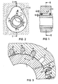
- a cam 2 is to be attached to a smooth, cylindrical shaft 1. This is held in a desired position with respect to the shaft 1 by a pliers-like device 3.
- the cam 2 is provided on its inner contour with one or more grooves 21 into which first wedges 4 are inserted, first in the position designated by A in FIG. 3, in which they step completely back into the groove 21.
- the first wedges 4 can have different cross sections adapted to the shape of the groove 21, as is evident from the alternative designs shown in the lower right part of FIG. 3.
- a cutting edge 43 formed on the first wedges 4 has the shape of a special hard metal particle 431, which is soldered to the body of the wedge 4 in a known manner.
- first wedges 4 Once all the first wedges 4 have been inserted into their corresponding grooves, the shaft 1 and the cam 2 are rotated relative to one another in the direction indicated by the arrows.
- the first wedges 4 are forcibly rotated into their second end position, designated B, with their cutting edge 43 digging into the surface of the shaft 1 made of relatively soft material.
- the free space remaining in the grooves 21 can now be filled in by inserting second wedges 5.
- a notch 42, 52 is then hammered into the first and / or second wedges 4, 5 with the aid of a chisel-like tool, whereby they are also finally fixed in the axial direction.
- the first wedge 4 may have an oversize 44 at one end, preferably that which is first inserted into the groove 21, due to the slightly beveled bottom surface. Then it is already digging to a certain extent into the surface of the shaft 1 and, without being able to slide on it, is brought securely into the end position B when the latter is rotated relative to the cam 2.
Description
- Die vorliegende Erfindung betrifft ein Verfahren nach dem Oberbegriff des 1. Anspruchs, mit dem Antriebselemente, z. B. Nocken, Lager oder Zahnräder auf einer glatten Welle befestigt werden können, sowie besondere Ausgestaltungen der hierzu verwendeten Teile. Die Erfindung wird im folgenden am Beispiel der Herstellung von Nockenwellen für Verbrennungskraftmaschinen beschrieben, ist jedoch nicht auf diesen Anwendungsfall beschränkt, sondern überall dort einsetzbar, wo Bauteile unverdrehbar und axial unverschiebbar auf glatten Wellen befestigt werden sollen. Dies insbesondere dann, wenn für die Großserienfertigung Lösungen erforderlich werden, die weniger aufwendig sind als die sonst im Maschinenbau verwendete Befestigung mit einem Paßkeil (auch Feder genannt), der in eine zu diesem Zweck in die Welle eingefräste Ausnehmung eingelegt wird. Eine Übersicht der hierfür bereits vorgeschlagenen Lösungen gibt die DE-A-23 36 241.
- Diesem Stand der Technik gegenüber besteht die Aufgabe der vorliegenden Erfindung darin, ein für diese Zwecke besser geeignetes Verfahren anzugeben, das es gestattet, als Grundmaterial für die Wellen statt teurer Drehteile erheblich billiger herzustellende Präzisionsrohre zu verwenden, die nicht vorbearbeitet werden müssen und auf denen die darauf zu befestigenden Teile in wenigen Arbeitsgängen rein formschlüssig fixiert werden.
- Die Lösung dieser Aufgabe geschieht durch die im kennzeichnenden Teil des 1. Verfahrensanspruchs angegebenen Maßnahmen. Es wird eine Keilverbindung hergestellt, bei der sich die Keile in die Oberfläche der Welle eingraben und so eine formschlüssige Verbindung bilden, sowie gegenüber einem späteren Lockern durch z. B. Vibrationen abgesichert werden.
- Um auch die Sicherheit der Positionierung in der Richtung der Wellenachse zu verbessern, empfiehlt sich die im 2. Anspruch vorgeschlagene weitere Ausgestaltung der Erfindung.
- Bei der Wellenverbindung nach dem Vorrichtungsanspruch 3 können die miteinander in Berührung kommenden Flächen von Keil und Nut leichter aufeinander abgleiten.
- Es ist bekannt, z. B. aus der DE-C-369 674, Längskanten der Keile als Schneidkanten auszubilden, damit sie sich leichter in die Wellenoberfläche eingraben. Die im 4. Anspruch vorgeschlagene Verwendung von in dieser Hinsicht verbesserten Keilen der Wellenverbindung erleichtert die Durchführung des Verfahrens erheblich.
- Die im 5. Anspruch vorgeschlagene weitere Verbesserung der Keile erleichtert zusätzlich einerseits das Eintreiben der Keile in die Wellenoberfläche und andererseits das Aufspreizen zur Sicherung ihrer Lage.
- Ausführungsbeispiele der Erfindung sind in der Zeichnung dargestellt, und zwar zeigt
- Figur 1 einen Längsaxialschnitt entsprechend der Linie I-I der Figur 2,
- Figur 2 einen Querschnitt entsprechend der Linie 11-11 der Figur 1 und
- Figur 3 in vergrößertem Maßstab die Einzelheit 111 der Figur 2, wobei auch alternative Ausführungsformen aufgenommen wurden.
- Auf einer glatten, zylindrischen Welle 1 soll ein Nocken 2 befestigt werden. Dieser wird, von einer zangenartigen Vorrichtung 3 gehalten, in die gewünschte Lage in bezug auf die Welle 1 gebracht. Der Nocken 2 ist an seiner Innenkontur mit einer oder mehreren Nuten 21 versehen, in die erste Keile 4 eingelegt werden, und zwar zunächst in der in Figur 3 mit A bezeichneten Stellung, bei der sie völlig in die Nut 21 zurücktreten. Die ersten Keile 4 können dabei verschiedene, an die Form der Nut 21 angepaßte Querschnitte aufweisen, wie dies an den im unteren rechten Teil der Figur 3 dargestellten Alternativ-Ausführungen deutlich wird. Dort ist auch die Abwandlung dargestellt, bei der eine an die ersten Keile 4 angeformte Schneidkante 43 die Form eines besonderen Hartmetallteilchens 431 hat, das in bekannter Weise mit dem Körper des Keils 4 verlötet ist. Sind alle ersten Keile 4 in ihre entsprechenden Nuten eingelegt worden, so werden die Welle 1 und der Nocken 2 in der durch die Pfeile angedeuteten Richtung gegeneinander verdreht. Die ersten Keile 4 werden dabei gewaltsam in ihre zweite, mit B bezeichnete Endlage gedreht, wobei sie sich mit ihrer Schneidkante 43 in die Oberfläche der aus verhältnismäßig weichem Werkstoff hergestellten Welle 1 eingraben. Der in den Nuten 21 verbliebene freie Raum kann nunmehr durch Einlegen von zweiten Keilen 5 ausgefüllt werden. In die ersten und/oder zweiten Keile 4, 5 wird dann mit Hilfe eines meißelartigen Werkzeuges an ihren Stirnseiten eine Kerbe 42, 52 eingeschlagen, wodurch sie auch in Achsrichtung endgültig fixiert werden.
- Der erste Keil 4 kann an seinem einen Ende, vorzugsweise demjenigen, das zuerst in die Nut 21 eingeführt wird, ein Übermaß 44 infolge leicht angeschrägter Bodenfläche aufweisen. Dann gräbt er sich bereits um ein gewisses Maß in die Oberfläche der Welle 1 und wird, ohne auf dieser abgleiten zu können, beim Verdrehen desselben gegenüber dem Nocken 2 sicher in die Endlage B gebracht.
Claims (5)
Priority Applications (1)
| Application Number | Priority Date | Filing Date | Title |
|---|---|---|---|
| AT85112476T ATE34437T1 (de) | 1984-10-17 | 1985-10-02 | Verfahren zum befestigen von antriebselementen auf einer zylindrischen welle mittels azimutal in diese einschneidender keile, sowie hiernach hergestellte wellenverbindung. |
Applications Claiming Priority (2)
| Application Number | Priority Date | Filing Date | Title |
|---|---|---|---|
| DE19843438065 DE3438065A1 (de) | 1984-10-17 | 1984-10-17 | Verfahren zum befestigen von antriebselementen auf einer zylindrischen welle mittels azimutal in diese einschneidender keile, sowie diese selbst |
| DE3438065 | 1984-10-17 |
Publications (2)
| Publication Number | Publication Date |
|---|---|
| EP0178536A1 EP0178536A1 (de) | 1986-04-23 |
| EP0178536B1 true EP0178536B1 (de) | 1988-05-18 |
Family
ID=6248115
Family Applications (1)
| Application Number | Title | Priority Date | Filing Date |
|---|---|---|---|
| EP85112476A Expired EP0178536B1 (de) | 1984-10-17 | 1985-10-02 | Verfahren zum Befestigen von Antriebselementen auf einer zylindrischen Welle mittels azimutal in diese einschneidender Keile, sowie hiernach hergestellte Wellenverbindung |
Country Status (6)
| Country | Link |
|---|---|
| EP (1) | EP0178536B1 (de) |
| JP (1) | JPS6196207A (de) |
| AT (1) | ATE34437T1 (de) |
| BR (1) | BR8505112A (de) |
| DE (2) | DE3438065A1 (de) |
| ES (1) | ES8704600A1 (de) |
Families Citing this family (3)
| Publication number | Priority date | Publication date | Assignee | Title |
|---|---|---|---|---|
| DE19608983A1 (de) | 1995-03-17 | 1996-09-19 | Volkswagen Ag | Steuerwelle und Verfahren zu ihrer Herstellung |
| DE59808217D1 (de) * | 1997-03-21 | 2003-06-12 | Stefan Battlogg | Nockenwelle |
| AT501273B8 (de) * | 2005-01-17 | 2007-02-15 | Avl List Gmbh | Nockenwelle für eine hubkolbenmaschine |
Family Cites Families (4)
| Publication number | Priority date | Publication date | Assignee | Title |
|---|---|---|---|---|
| US1406247A (en) * | 1920-11-08 | 1922-02-14 | Igoe Brothers | Shaft coupling |
| DE396673C (de) * | 1922-05-21 | 1924-06-20 | Alfred Kadlubowski Dipl Ing | Umfangsverkeilung |
| DE872886C (de) * | 1951-11-22 | 1953-04-09 | Ringfeder Gmbh | Spannelement |
| DE2336241A1 (de) * | 1973-07-17 | 1975-02-06 | Volkswagenwerk Ag | Poly-metallische, zusammengefuegte steuerwellen |
-
1984
- 1984-10-17 DE DE19843438065 patent/DE3438065A1/de not_active Withdrawn
-
1985
- 1985-10-02 DE DE8585112476T patent/DE3562808D1/de not_active Expired
- 1985-10-02 AT AT85112476T patent/ATE34437T1/de not_active IP Right Cessation
- 1985-10-02 EP EP85112476A patent/EP0178536B1/de not_active Expired
- 1985-10-15 JP JP60229759A patent/JPS6196207A/ja active Pending
- 1985-10-15 BR BR8505112A patent/BR8505112A/pt unknown
- 1985-10-16 ES ES547934A patent/ES8704600A1/es not_active Expired
Also Published As
| Publication number | Publication date |
|---|---|
| DE3438065A1 (de) | 1986-04-24 |
| EP0178536A1 (de) | 1986-04-23 |
| BR8505112A (pt) | 1986-07-29 |
| ATE34437T1 (de) | 1988-06-15 |
| ES547934A0 (es) | 1987-04-01 |
| ES8704600A1 (es) | 1987-04-01 |
| JPS6196207A (ja) | 1986-05-14 |
| DE3562808D1 (en) | 1988-06-23 |
Similar Documents
| Publication | Publication Date | Title |
|---|---|---|
| EP0292795B1 (de) | Hohlwelle mit durch Aufweiten derselben darauf befestigten Antriebselementen mit axial unterschiedlichen Werkstoffeigenschaften | |
| EP1005401B1 (de) | Verfahren zur herstellung einer lösbaren verbindung zwischen zwei bauteilen und verbindungssystem zur durchführung des verfahrens | |
| EP0170187B1 (de) | Verfahren zum Befestigen von Antriebselementen auf einer zylindrischen Welle | |
| DE3235876A1 (de) | Axiallager, insbesondere klotzlager | |
| DE60007754T2 (de) | Schneideinsatzsitz | |
| EP0551795B1 (de) | Werkzeug zum Schlagbohren und Meisseln und Werkzeugaufnahme für diese Werkzeuge | |
| DE3817079C2 (de) | Formschlüssige Verbindung zwischen zwei aus Blech bestehenden Teilen eines Fahrzeuges und Verfahren zu ihrer Herstellung | |
| DE3642438C2 (de) | Anordnung mit einem axialen Haltekörper | |
| DE60111322T2 (de) | Verriegelungsanordnung für sphärische Lager und Verrieglungsverfahren davon | |
| DE102007038254B4 (de) | Kupplungsglied für eine Mitnehmerkupplung und Herstellungsverfahren | |
| EP0178537B1 (de) | Verfahren zum Befestigen von Antriebselementen auf einer Welle mittels axial in diese einschneidender Keile, sowie diese selbst | |
| DE3606075A1 (de) | Drehgelenk | |
| DE19735709A1 (de) | Hinterschnittdübel | |
| EP0178536B1 (de) | Verfahren zum Befestigen von Antriebselementen auf einer zylindrischen Welle mittels azimutal in diese einschneidender Keile, sowie hiernach hergestellte Wellenverbindung | |
| DE10216137A1 (de) | Verdrehgesicherte Anlaufscheibe | |
| DE2655728C2 (de) | Lösbare Naben-Wellenverbindung | |
| DE710596C (de) | Kolbenbolzensicherung | |
| CH653754A5 (de) | Stirnzahnradgetriebe. | |
| DE102005026554B4 (de) | Verfahren zum Einbringen einer Verriegelungsnut in eine Nutflanke | |
| DE3108197A1 (de) | Einsatz fuer eine verbundplatte | |
| DE2426952C3 (de) | Bremsscheibe für Scheibenbremsen | |
| DE3223994C2 (de) | Axialsicherungselement | |
| DE19548403C2 (de) | Verfahren zur Herstellung einer Metalldichtung mit erhöhter Dichtigkeit | |
| EP0290654B1 (de) | Spreizdübel zur formschlüssigen Verankerung in einem Bohrloch | |
| DE3606073A1 (de) | Drehgelenk |
Legal Events
| Date | Code | Title | Description |
|---|---|---|---|
| PUAI | Public reference made under article 153(3) epc to a published international application that has entered the european phase |
Free format text: ORIGINAL CODE: 0009012 |
|
| AK | Designated contracting states |
Kind code of ref document: A1 Designated state(s): AT BE CH DE FR GB IT LI LU NL SE |
|
| 17P | Request for examination filed |
Effective date: 19860527 |
|
| 17Q | First examination report despatched |
Effective date: 19870625 |
|
| GRAA | (expected) grant |
Free format text: ORIGINAL CODE: 0009210 |
|
| AK | Designated contracting states |
Kind code of ref document: B1 Designated state(s): AT BE CH DE FR GB IT LI LU NL SE |
|
| REF | Corresponds to: |
Ref document number: 34437 Country of ref document: AT Date of ref document: 19880615 Kind code of ref document: T |
|
| REF | Corresponds to: |
Ref document number: 3562808 Country of ref document: DE Date of ref document: 19880623 |
|
| ET | Fr: translation filed | ||
| ITF | It: translation for a ep patent filed |
Owner name: STUDIO JAUMANN |
|
| GBT | Gb: translation of ep patent filed (gb section 77(6)(a)/1977) | ||
| REG | Reference to a national code |
Ref country code: CH Ref legal event code: PUE Owner name: EMITEC GESELLSCHAFT FUER EMISSIONSTECHNOLOGIE MBH |
|
| NLS | Nl: assignments of ep-patents |
Owner name: EMITEC GESELLSCHAFT FUER EMISSIONSTECHNOLOGIE MBH |
|
| PLBE | No opposition filed within time limit |
Free format text: ORIGINAL CODE: 0009261 |
|
| STAA | Information on the status of an ep patent application or granted ep patent |
Free format text: STATUS: NO OPPOSITION FILED WITHIN TIME LIMIT |
|
| 26N | No opposition filed | ||
| REG | Reference to a national code |
Ref country code: FR Ref legal event code: TP |
|
| ITPR | It: changes in ownership of a european patent |
Owner name: CESSIONE;EMITEC GESELLSCHAFT FUR EMISSIONSTECHNOLO |
|
| PGFP | Annual fee paid to national office [announced via postgrant information from national office to epo] |
Ref country code: GB Payment date: 19910920 Year of fee payment: 7 |
|
| PGFP | Annual fee paid to national office [announced via postgrant information from national office to epo] |
Ref country code: SE Payment date: 19910927 Year of fee payment: 7 |
|
| PGFP | Annual fee paid to national office [announced via postgrant information from national office to epo] |
Ref country code: FR Payment date: 19911007 Year of fee payment: 7 |
|
| PGFP | Annual fee paid to national office [announced via postgrant information from national office to epo] |
Ref country code: AT Payment date: 19911015 Year of fee payment: 7 |
|
| PGFP | Annual fee paid to national office [announced via postgrant information from national office to epo] |
Ref country code: LU Payment date: 19911018 Year of fee payment: 7 |
|
| PGFP | Annual fee paid to national office [announced via postgrant information from national office to epo] |
Ref country code: CH Payment date: 19911025 Year of fee payment: 7 |
|
| ITTA | It: last paid annual fee | ||
| PGFP | Annual fee paid to national office [announced via postgrant information from national office to epo] |
Ref country code: NL Payment date: 19911031 Year of fee payment: 7 Ref country code: DE Payment date: 19911031 Year of fee payment: 7 |
|
| PGFP | Annual fee paid to national office [announced via postgrant information from national office to epo] |
Ref country code: BE Payment date: 19911211 Year of fee payment: 7 |
|
| EPTA | Lu: last paid annual fee | ||
| PG25 | Lapsed in a contracting state [announced via postgrant information from national office to epo] |
Ref country code: LU Free format text: LAPSE BECAUSE OF NON-PAYMENT OF DUE FEES Effective date: 19921002 Ref country code: GB Effective date: 19921002 Ref country code: AT Effective date: 19921002 |
|
| PG25 | Lapsed in a contracting state [announced via postgrant information from national office to epo] |
Ref country code: SE Effective date: 19921003 |
|
| PG25 | Lapsed in a contracting state [announced via postgrant information from national office to epo] |
Ref country code: LI Effective date: 19921031 Ref country code: CH Effective date: 19921031 Ref country code: BE Effective date: 19921031 |
|
| BERE | Be: lapsed |
Owner name: EMITEC G. FUR EMISSIONSTECHNOLOGIE M.B.H. Effective date: 19921031 |
|
| PG25 | Lapsed in a contracting state [announced via postgrant information from national office to epo] |
Ref country code: NL Effective date: 19930501 |
|
| GBPC | Gb: european patent ceased through non-payment of renewal fee |
Effective date: 19921002 |
|
| NLV4 | Nl: lapsed or anulled due to non-payment of the annual fee | ||
| PG25 | Lapsed in a contracting state [announced via postgrant information from national office to epo] |
Ref country code: FR Effective date: 19930630 |
|
| REG | Reference to a national code |
Ref country code: CH Ref legal event code: PL |
|
| PG25 | Lapsed in a contracting state [announced via postgrant information from national office to epo] |
Ref country code: DE Effective date: 19930701 |
|
| REG | Reference to a national code |
Ref country code: FR Ref legal event code: ST |
|
| EUG | Se: european patent has lapsed |
Ref document number: 85112476.8 Effective date: 19930510 |