EP0178472B1 - Vorrichtung zum Ablösen anhaftender Nahrungsmittelprodukte von einer Trägerfläche - Google Patents
Vorrichtung zum Ablösen anhaftender Nahrungsmittelprodukte von einer Trägerfläche Download PDFInfo
- Publication number
- EP0178472B1 EP0178472B1 EP19850111737 EP85111737A EP0178472B1 EP 0178472 B1 EP0178472 B1 EP 0178472B1 EP 19850111737 EP19850111737 EP 19850111737 EP 85111737 A EP85111737 A EP 85111737A EP 0178472 B1 EP0178472 B1 EP 0178472B1
- Authority
- EP
- European Patent Office
- Prior art keywords
- tray
- releasing
- meat
- conveyor belt
- rollers
- Prior art date
- Legal status (The legal status is an assumption and is not a legal conclusion. Google has not performed a legal analysis and makes no representation as to the accuracy of the status listed.)
- Expired
Links
Images

Classifications
-
- A—HUMAN NECESSITIES
- A22—BUTCHERING; MEAT TREATMENT; PROCESSING POULTRY OR FISH
- A22C—PROCESSING MEAT, POULTRY, OR FISH
- A22C17/00—Other devices for processing meat or bones
- A22C17/0006—Cutting or shaping meat
- A22C17/0033—Cutting slices out of a piece of meat
-
- A—HUMAN NECESSITIES
- A21—BAKING; EDIBLE DOUGHS
- A21C—MACHINES OR EQUIPMENT FOR MAKING OR PROCESSING DOUGHS; HANDLING BAKED ARTICLES MADE FROM DOUGH
- A21C9/00—Other apparatus for handling dough or dough pieces
- A21C9/08—Depositing, arranging and conveying apparatus for handling pieces, e.g. sheets of dough
-
- Y—GENERAL TAGGING OF NEW TECHNOLOGICAL DEVELOPMENTS; GENERAL TAGGING OF CROSS-SECTIONAL TECHNOLOGIES SPANNING OVER SEVERAL SECTIONS OF THE IPC; TECHNICAL SUBJECTS COVERED BY FORMER USPC CROSS-REFERENCE ART COLLECTIONS [XRACs] AND DIGESTS
- Y10—TECHNICAL SUBJECTS COVERED BY FORMER USPC
- Y10T—TECHNICAL SUBJECTS COVERED BY FORMER US CLASSIFICATION
- Y10T83/00—Cutting
- Y10T83/202—With product handling means
- Y10T83/2092—Means to move, guide, or permit free fall or flight of product
- Y10T83/2192—Endless conveyor
- Y10T83/2194—And means to remove product therefrom
Definitions
- This invention relates generally to food processing machinery, and, more particularly, to machinery, for releasing and removing food products adhered to support surfaces.
- the problem of sticking can be particularly troublesome where the food product is in the form of a thin strip or sheet. If a thin strip or sheet sticks to an underlying support surface, freeing of the thin piece is made even more difficult, and a major portion of the thin piece may be lost during the process of releasing it from the support surface. The freeing of a thin piece of food product is complicated even further when the piece is stuck over a large portion of its surface area, and when the food product is relatively fragile. While the releasing of such food products from supporting surfaces can be a problem in a home environment, the problem is magnified in the food processing industry and can often pose a major obstacle to the automation of food preparation processes.
- meat jerky may be prepared on a commercial scale for human or animal consumption by preparing a meat-containing mixture and extruding the mixture through a die to form a strip.
- the strip is extruded onto a tray having apertures through the bottom thereof, to support the strip during further processing.
- the presence of the apertures is desirable, as in the next step the strips of extruded meat product, supported by the tray, are placed into a drying oven wherein the moisture contained in the extruded strip is removed by heating at a relatively low temperature.
- the apertures permit greater air circulation to accelerate drying.
- the extruded meat strips usually stick to the trays for two reasons.
- proteinaceous material contained within the meat can bake onto the interface between the support surface and the strip to bind the meat strip to the tray.
- the prior practice has been to invert the tray over a flat surface and then repeatedly pound the tray against the flat surface to loosen the meat strips so that they fall to the flat surface.
- This approach often caused the meat strip to break into shorter pieces, which typically were not of the proper lengths for cutting and packaging at the desired uniform lengths.
- some of the dried meat strip was wasted.
- the meat strips would break into shorter lengths during pounding of the trays because, after drying, the meat strips are relatively fragile and readily torn.
- the dried meat strips are similar to many other cooked or dried food products which stick to trays or other types of preparation surfaces and must be freed to allow subsequent processing.
- the prior practice was essentially a manual operation, and extensive labour was required.
- Another approach is to attempt to force a knife between the strip of dried meat and the surface of the tray bottom to which it has adhered.
- Both of these approaches suffer from a severe disadvantage, in that the dried meat strip is fragile and tends to break into short lengths when so released. The short broken lengths are not readily packaged for sale to the consumer. In some cases, the short pieces are unacceptable for commercial sales and must be discarded, resulting in substantial waste. Further, these two methods of releasing the meat product from the tray are highly labour intensive and substantially increase the cost of the final product.
- DE-C-637869 (Anciens Etablatoriums and others) disclose apparatus for use in removing a food product from a support surface and arranging it for further processing, which support surface has a plurality of apertures extending therethrough, the apparatus comprising a releasing roller, which extends underneath the support surface and has radially extending projections for extending through the apertures in order to push the food product upwardly and away from the support surface.
- the support surface in this prior art document is a wire lattice which acts as a conveyor belt for conveying dough through an oven.
- a brush roller At the exit end of the oven there is a brush roller which has bristles extending through the openings in the wire lattice to push the cooked dough upwardly from the wire lattice.
- the apparatus must gently release the food product to avoid breakage and waste.
- the apparatus should be compatible with existing processing machinery to avoid large capital expenditures, and preferably provide the separated food product to further processing machinery in an orderly presentation, to facilitate yet further automation of the processing.
- the present invention fulfills this need, and further provides related advantages.
- the present invention is characterised in that the support surface is provided by a tray and in that the apparatus further comprises first and second conveyor belts, which are arranged in line with each other for supporting and moving the tray in the direction from the first to the second conveyor belt, and a releasing station, which is interposed between the adjacent ends of the conveyor belts and includes the releasing roller and two restraining rollers, which rollers extend transversely of the conveying direction of the conveying belts, the restraining rollers being disposed above and offset from the releasing roller so that the releasing roller lies between the restraining rollers.
- the apparatus further comprises, at the releasing station, at least one further releasing roller and at least one further restraining roller, the number of releasing rollers and the number of restraining rollers differing by one and being offset from one another.
- the apparatus also further comprises a third conveyor belt, which is positioned transversely of and below the end of the second conveyor belt for receiving trays therefrom, the third conveyor belt having a depressed central region and raised side regions extending in the conveying direction of the third conveyor belt, the width of the depressed central region being less than the length of a tray so that the ends of the tray can be supported by the raised side regions, and a tray inverter which is positioned at the end of the second conveyor belt and comprises a tray drop channel for receiving a tray and conducting the tray downwardly with a side edge leading, the leading side edge being directed into contact with the third conveyor belt so that the tray is inverted by the movement of the third conveyor belt with the ends of the tray being supported by the side regions of the third conveyor belt.
- a third conveyor belt which is positioned transversely of and below the end of the second conveyor belt for receiving trays therefrom, the third conveyor belt having a depressed central region and raised side regions extending in the conveying direction of the third conveyor belt, the width of the depressed central region being
- the apparatus further comprises a peeling plate having a forward edge which is positioned along the third conveyor belt and at a height which is between the depressed central region and raised side regions of the third conveyor belt and extends in a direction opposite to that of the conveying direction of the third conveyor belt.
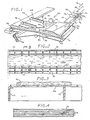
- the drawings show apparatus for releasing and removing strips of extruded meat products from trays.
- One such extruded meat product may be formed by mixing together the following ingredients in the indicated amounts, by weight: 75% meat by-products, 15% beef, 1% wheat flour, 1% cane molasses, 2% dextrose, 2% salt, 2% water and 2% spices and preservatives. This mixture is then extruded or otherwise formed into meat strips 10 having dimensions of about 31.75mm (1-1/4 inch) wide by 4.19mm (0.165 inch) thick by 1.22m (48 inches) long.
- the strips have a relatively high moisture content and include fibres of meat, they cannot be readily and neatly cut in the as-extruded form into the desired length of about 108mm (4-1/4 inches) for packaging. It is therefore necessary to dry the meat strips first, before cutting into the shorter pieces.
- FIGs 2, 3 and 4 illustrate a tray 12 onto which the meat strips 10 are extruded.
- a tray 12 is typically made of plastics and is about 152mm (6 inches) wide and 1.22mm (48 inches) long, so that four strips 10 are supported thereon as illustrated in Figure 4, with the underside of the tray 12 having crosswise and length wise ribs 14 for strength.
- An array of apertures 18 are formed through the surface of each of the trays 12. Each aperture 18 is about 9.53mm (3/8 inches) wide and 19.1mm (3/4 inches) long, and there are typically about 544 apertures per tray.
- the trays 12 are stacked on racks or carts and placed into a drying oven operating at about 65.6-76.7°C (150-170°F) for a period of 4-5 hours, to dry the moisture from the meat strips 10 to form a dried meat or jerky product.
- the apertures 18 in the bottom of the trays 12 improve the circulation of dry air to the meat strips 10.
- the meat strips 10 tend to sag into the apertures 18, thereby causing sticking of the dried meat strips 10 to the walls of the apertures 18, as illustrated in Figure 3.
- the proteinaceous matter of the meat also bakes to the surface of the tray, causing sticking.
- the meat strips 10 tend to shrink due to the removal of moisture, and typically have a dried cross sectional size of about 25.4mm (1 inch) by 3.18mm (1/8 inch).
- An apparatus generally denoted by the numeral 20, releases the meat strips 10 from the tray 12 as the tray passes along a tray conveyer 22 and through a releasing station 24. Passage through the releasing station 24 separates the underside of the meat strip 10 from the surface of the tray 12 over a major fraction of the area of the meat strip 10, but typically not all of the meat strip is completely unstuck or released.
- the release and separation of the meat strips 10 from the tray 12 is completed, and the meat strips 10 are removed from the tray 12 and arranged in an orderly array for further processing, specifically for a cutting operation to produce 108mm (4-1/4 inch) long strips for packaging.
- the tray 12 reaches the end of the tray conveyor 22, it enters a tray inverter 26, wherein the tray 12 and the meat strips 10 contained thereon are inverted onto a tray remover 28.
- the tray remover 28 has a central depressed region 30 and two raised regions 32 along each side of the tray remover 28, the depressed region 30 and the raised regions 32 extending parallel to the direction of motion of the tray 12 along the tray remover 28.
- Each tray 12 is supported at its ends on the two raised regions 32, with the centre portion of the tray 12 suspended over the depressed region 30. Those meat strips which were fully released in the releasing station 24 fall downwardly from the inverted tray and lie on the tray remover 28.
- a peeling plate 34 is positioned at a height intermediate between the bottom of the depressed region 30 and the top of the raised regions 32, within the depressed region 30. As the inverted trays 12 pass over the plate 34, the trays 12 are forced upwardly, while any partially released meat strips hanging downwardly from the inverted trays 12 are peeled away from the trays 12 by the peeling plate 34. The trays 12 are then conveyed upwardly for gathering and reuse, and the separated meat strips are conveyed under the peeling plate 34 for further processing.
- trays 12 from a drying oven are loaded onto a tray conveyor moving toward the releasing station 24, as indicated by the direction of an arrow 36 in Figures 1 and 5.
- the tray conveyor 22 moves the trays 12 on a first moving belt 38, which is supported and moved by a pair of first pulleys 40.
- the first pulleys 40 are driven by a first motor 42, so that the trays 12 move along the tray conveyor 22 toward the releasing station 24.
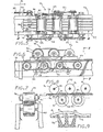
- the releasing station 24 comprises two sets of driven rollers, a first set of releasing rollers 44 positioned below the tray 12 as it passes through the releasing station 24, and a second set of restraining rollers 46 positioned above the tray 12 as it passes through the releasing station 24.
- the rollers 44 and 46 are chain or belt driven by the first motor 42, to have a surface speed equal to the rate of linear movement of the tray 12 through the rollers 44 and 46.
- the tray 12 is carried forward by a second moving belt 47, which is supported on a pair of second pulleys 51 and belt driven by the first motor 42.
- the first motor 42 drives the first and second moving belts 38 and 47, and the rollers 44 and 46, through a chain or belt drive system 57.
- the releasing rollers 44 are cylindrical rubber rollers turning about their cylindrical axes on shafts 48. Projecting outwardly from the surface of each of the releasing rollers 44 is a plurality of protrusions in the form of projections 50, each projection having a transverse cross-sectional area smaller than that of the apertures 18 in the tray 12, so that the projections 50 penetrate upwardly through the apertures 18 to contact an underside 52 of the meat strip 10. In this way, the projections 50 gently contact the underside 52 of the meat strip 10 to lift the meat strip 10 upwardly as it passes over the releasing roller 44, as best illustrated in Figures 8 and 9.
- the height of the releasing rollers 44 is adjusted by moving pillow block bearings 49 upwardly or downwardly using cams 53, so that the contact force between the projections 50 and the meat strip 10 may be decreased or increased, as required.
- the projections 50 are formed of a soft rubber material, so that they may be displaced sideways in a horizontal plane by small amounts if the projections 50 do not immediately engage the apertures 18. Thus, even though the spacings of the projections 50 on the releasing roller 44 may not exactly match the center-to-center spacing of the apertures 18, the sideways flexibility of the projections 50 allows the projections 50 to find their way into and upwardly through the apertures 18 to contact the underside 52 of the meat strip 10. Additionally, the projections 50 may be randomly placed on the surface of the releasing roller 44, or be placed in a spiral pattern on the surface of the releasing roller 44. The spiral pattern further aids in registering the projections 50 with the apertures 18.
- a commercially available roller typically used as a rubber brush, may be purchased from FMC Corporation, San Jose, California, as catalog number 4834-682-114.
- This roller 44 is a 152.4mm (6-inch) long by 101.6mm (4-inch) diameter cylinder, having approximately 320 tapered cylindrical rubber protections 50 thereon, with each projection 50 having a maximum cross-sectional diameter of about 4.76mm (3/16inch) and a height of about 31.8mm (1-1/4 inches).
- the projections 50 are arranged on this roller in a spiral pattern, thus increasing the likelihood of registry between some projections 50 and the apertures 18.
- the tray 12 and the strips 10 tend to move upwardly and must be restrained from such movement, to exert a parting force between the meat strips 10 and the tray 12.
- the restraining rollers 46 mounted above the tray 12, are positioned to contact the top of the meat strip 10 to prevent it and the tray 12 from moving upwardly.
- the restraining rollers 46 turn on shafts 54, which are mounted in pillow block bearings 56.
- the pillow block bearings 56 are adjustable upwardly and downwardly, to allow control over the freedom of the meat strips 10 and tray 12 to move upwardly.
- the restraining rollers 46 are 127mm (5-inch) diameter by 152.4mm (6-inch) long rollers made of a plastics such as nylon, PTFE or polyethylene material, to provide a low-friction contact between the back-up rollers 46 and the strips 10.
- the restraining rollers 46 are adjusted to contact the tops of the strips 10.
- the restraining rollers 46 could contact portions of the tray 12, to provide the restraining function required to prevent gross upward movement of the meat strips 10 and tray 12 under the upward lifting of the releasing rollers 44.
- Gross upward movement of the tray 12 would be a movement that lifts the entire tray 12 or strip 10 upwardly.
- the restraining rollers 46 prevent gross upward movement while allowing the local upward movement and flexure caused by the releasing rollers 44, as illustrated in Figures 8 and 9.
- the releasing rollers 44 and the restraining rollers 46 are horizontally offset from each other.
- the offset is parallel to the direction of motion 36 of the first moving belt 38.
- the total number of releasing rollers 44 preferably differs from the total number of restraining rollers 46 by one, so that there is either one more releasing roller 44 than restraining roller 46, or one more restraining roller 46 than releasing roller 44, thereby creating a symmetrical offset pattern of rollers 44 and 46, when viewed from the side.
- two releasing rollers 44 and three back-up rollers 46 are illustrated.
- the horizontal offset between the releasing rollers 44 and the restraining rollers 46 causes the meat strip 10 and tray 12 to flex alternately upwardly and downwardly as they pass over the individual rollers 44 and 46.
- This flexing action of the meat strips 10 and tray 12 aids in the release of the meat strips 10 from the tray 12, in addition to the direct upward force of the projections 50 directly against the underside ; 52 of the meat strips 12, through the apertures 18.
- the function of the releasing rollers 44 and the restraining rollers 46 is to gently separate and release the meat strip 10 or other fragile food product from contact with the tray 12.
- the offset rollers 44 and 46 do not perform this function, as the projections 50 on the releasing rollers 44 contact the meat strips 10 with a relatively gentle force which does not have a penetrating or tenderising effect on the dried meat strips 10.
- the mechanical effect of the rollers 44 and 46 is to gently dislodge, separate, and release the meat strip 10 by forcing them upwardly from the tray 12, not to act directly upon the meat to alter its struction in any respect.
- the term "gently”, as used herein, refers to an absence of substantial penetration and modification of the food product itself.
- the tray 12 passes through the releasing station 24, some of the meat strips 10 are released and separated from the tray 12 along their entire length and width. Such meat strips 10 could at this stage be lifted off the tray 12. In the majority of instances, however, the meat strip 10 is partially released from adhering to the tray 12. Some relatively small portions of the area of the underside 52 of the meat strip 10 may remain stuck to the tray 12, particularly near to the ends of the meat strips 10. The reason that such partially released meat strips 10 do not release fully from the tray 12 is not known with certainty, but the ends of the tray 12 are not fully restrained by the restraining rollers 46 when passing over the releasing rollers 44.
- the ends of the tray 12 are therefore lifted so that the projections 50 do not fully penetrate the apertures 18, leaving the meat strip 10 in such areas possibly stuck to the bottom of the tray 12. Also, at the ends of the trays 12, the projections 50 do not readily fit into the corners to release the portions of the strips 10 which hang over the ends of the trays 12. The degree of partial release may be improved by increasing the number and varieties of rollers 44 and 46, until complete release is achieved for all areas of all meat strips 10.
- Partially dried meat strips having a width of about 25.4mm (1 inch), a thickness of about 3.18mm (1/8 inch), and a length of 1.22m (48 inches) are very difficult to handle and align on a commercial scale, wherein as many as 3,000 trays and 12,000 strips of meat may be processed per hour.
- the strips of meat are more fragile and easily torn than comparable pieces of natural meat, and therefore subject to breakage in this highly elongate, very thin form.
- the part of the apparatus described next permits such handling and alignment of the meat strips 10, without introduction of expensive manual labor and without damage to the meat strips.
- the upright trays emerging from the releasing station 24 on the second moving belt 47 are conducted into the tray inverter 26.
- the tray inverter 26 includes an end stop 70 located at the end of the tray conveyor 22. Forward motion of the trays 12 is thereby halted and the tray 12 slides sideways downwardly along an inclined surface 72, as best illustrated in Figure 11.
- the initial motion of the tray 12 down the inclined surface 72 is aided by an angled intersection 74 between the inclined surface 72 and the upper surface of the tray conveyor 22, so that the front end of the tray 12 contacting the end stop 70 is suspended and straightened over the inclined surface 72.
- the weight of the front end of the tray 12 then pulls the tray 12 sideways and down the inclined surface 72.
- the leading or lowest side edge of the tray 12 tips downwardly so that the tray 12 is tipped on its side to a generally sideways vertical position by contact with a back plate 79, as illustrated at numeral 78 in Figure 11. Any fully released meat strips are held in a straight aligned position by contact with the back plate 79 as the tray 12 is tipped and moves downwardly through a tray drop channel 81 between the back plate 79 and the lower end 76. The tray 12 then passes on to the tray remover 28.
- the tray remover 28 comprises a table 82 supporting a third moving belt 80, also termed a strip conveyor belt, the peeling plate 34 and associated structure.
- the table 82 is positioned so that the third moving belt 80 is below the tray conveyor 22 and the tray inverter 26, and oriented so that the third moving belt 80 moves in a direction opposite to that in which the trays 12 slide down the inclined surface 72.
- the motion of the third moving belt 80 completes the turning and inversion of the sideways oriented vertical tray 78, so that the tray is deposited from the tray inverter 26 in an inverted or upside-down position as indicated by a tray 86 on the third moving belt 80.
- the third moving belt 80 is generally perpendicularto the tray conveyor 22, the inverted tray 86 lies across the width of the third moving belt 80.
- the third moving belt 80 is supported on a set of crowned pulleys 88 and driven by a second motor 90.
- the third moving belt 80 is preferably formed of a highly wear resistant, flexible fabric-like material, so that the belt may flex to follow the contours of its supporting surface, as discussed subsequently.
- the surface of the third moving belt 80 preferably has transverse ribs or ridges thereon to catch the leading edge of the tray 12 as it contacts the belt 80.
- the belt is formed of a commercially available conveyor belt material such as 3- ply Fabsyn polyester belt, available from Fab- reeka Products Co. Inc., Boston, Massachussetts. A smooth belt, not having ribs thereon, is also effective.
- the upper surface of the table 82, upon which the third moving belt 80 rides, is contoured to facilitate the removal of the meat strips 10 from the inverted trays 86.
- the third moving belt 80 passes over the crowned pulleys 88, the third moving belt 80 is generally flat.
- the third moving belt 80 then passes on to an upper support surface 92 of the table 82.
- the upper support surface 92 is contoured to have a raised portion 94 adjacent to each transverse edge of the upper support surface 92, and a depressed portion 96 in the center of the upper support surface 92.
- the raised portion 94 and depressed portion 96 of the support surface 92 produce the similarly configured raised region 32 and depressed region 30 in the third moving belt 80 as it rides over the upper support surface 92.
- the transition region between the raised portion 94 and the depressed portion 96 is gently sloped, so as to avoid any snagging of the third moving belt 80.
- the width of the depressed portion 96 and the corresponding depressed region 30 is less than the length of the inverted tray 86 so that the ends of the inverted tray 86 are supported by the raised regions 32 on the opposite sides of the third moving belt 80. Any meat strips 10 which have been fully released from the tray 12 at the releasing station lie on the surface of the third moving belt 80.
- the peeling plate 34 is a longitudinally tapered plate having a pointed leading edge, the point extending oppositely to the motion of the third moving belt 80, the motion being indicated by the arrow 84.
- a point 100 of the peeling plate 34 is disposed just below the inverted tray 86, in the gap between the inverted tray 86 and the third moving belt 80 in the depressed region 30.
- the point 100 is thereby interposed between the inverted tray 86 and any hanging meat strip 98, so that the hanging meat strip 98 is gradually and gently peeled away from the inverted tray 86 as the inverted tray 86 progresses forwardly in the direction of motion 84. Final release and removal of any partially released meat strips 10 is thereby ensured.
- the hanging meat strips 98 are forced downwardly to aid the point 100 in passing between the inverted tray 86 and the strips 98 by a downward jet of compressed air from a manifold 99 positioned above the longitudinal center of the inverted tray 86 as it reaches the point 100. This air jet forces the strip 98 downwardly to widen the gap between the strip 98 and the surface of the inverted tray 86.
- a pair of tray straightening rollers 101 are positioned to contact the surfaces of the inverted trays 86 near their ends, above the portion supported on the raised region 32.
- the rollers 101 are chain or belt-driven by the second motor 90 and hold the ends of the inverted trays 86 down tightly, thereby holding the entire inverted tray 86 straight to allow engagement with the peeling plate 34.
- the apparatus 20 has the special advantage of depositing the released and removed meat strips 105 in a uniform array so that, with minor adjustments to ensure alignment of the ends of the meat strips 105, the meat strips 105 may be so processed with a minimum of repositioning and alignment. The chance of damaging the fragile food product is thereby reduced, as is the need for the use of manual labour to reposition the pieces.
- the apparatus 20 also provides for the collection and return of emptied trays 104 for receiving newly extruded meat strips and reprocessing.
- the inverted tray 86 moves forwardly in the direction 84 and engages the peeling plate 34, it is gradually lifted upwardly as the hanging meat strips 98 are separated.
- the inverted tray 86 becomes the emptied tray 104.
- the emptied tray 104 is moved upwardly along an inclined surface 106 which forms a continuation of the peeling plate 34.
- the emptied tray 104 is moved forwardly by a fifth moving belt 108 supported on a pair of crowned pulleys 110 and chain or belt-driven in the direction of the arrow 84 by the second motor 90 at a rate of travel equal to that of the third moving belt 80.
- the fifth moving belt 108 does not support the tray but instead engages the inverted emptied tray 104 only to move it forwardly.
- the fifth moving belt 108 is a pair of thin continuous belts such as timing belts.
- the emptied tray 104 is moved forwardly in the direction of the arrow 84 to almost the end of the inclined surface 106, whereupon the emptied tray 104 is swept forwardly by a sweeper roller 114 driven by the second motor 90, to sweep the inverted trays 104 further in the direction of the arrow 84.
- the sweeper roller 114 is a roller having soft, rubber protrusions thereon to engage the emptied tray 104, of the same type as previously described for the releasing rollers 44.
- the sweeper roller 114 sweeps the emptied tray 104 onto a sixth moving belt 116, which collects the emptied trays 104 for stacking onto carts (not shown). The trays are then returned to the extrusion area for inspection, cleaning if necessary, and subsequent re-use.
- the tray 12 carrying meat strips 10 on the surface thereof is transported along the tray conveyor 22, and through the releasing station 24 to fully or partially release the meat strips 10 from the tray 12.
- the tray 12 then progresses along the tray conveyor 22 and is inverted by the tray inverter 26 onto the third moving belt 80.
- the inverted tray 86 which is supported by its ends on the raised regions 32 of the third moving belt 80, is passed over the peeling plate 34, so that all of the meat strips are separated to lie on the surface of the third moving belt 80, while all of the emptied trays 104 pass upwardly and to the sixth moving belt 116 for stacking, return and re-use.
- the food products are handled gently, automatically, and in an orderly fashion. Breakage and loss of the fragile food products is thereby minimized.
- the food products are delivered in an orderly array to subsequent processing machinery, and the trays are returned in an orderly fashion to the starting point of the process for re-use.
- the apparatus requires no manual labour, except for an operator to keep the machinery in working order and watch for any problems that might develop, and workers to load trays 12 into the machine and stack emptied trays 104.
- the apparatus may be constructed relatively inexpensively from commercially available components.
Landscapes
- Life Sciences & Earth Sciences (AREA)
- Engineering & Computer Science (AREA)
- Food Science & Technology (AREA)
- Wood Science & Technology (AREA)
- Zoology (AREA)
- Meat, Egg Or Seafood Products (AREA)
Claims (4)
Applications Claiming Priority (2)
| Application Number | Priority Date | Filing Date | Title |
|---|---|---|---|
| US651488 | 1984-09-17 | ||
| US06/651,488 US4645404A (en) | 1984-09-17 | 1984-09-17 | Apparatus for removing an adhered fragile food product from a support surface |
Publications (2)
| Publication Number | Publication Date |
|---|---|
| EP0178472A1 EP0178472A1 (de) | 1986-04-23 |
| EP0178472B1 true EP0178472B1 (de) | 1989-05-03 |
Family
ID=24613035
Family Applications (1)
| Application Number | Title | Priority Date | Filing Date |
|---|---|---|---|
| EP19850111737 Expired EP0178472B1 (de) | 1984-09-17 | 1985-09-17 | Vorrichtung zum Ablösen anhaftender Nahrungsmittelprodukte von einer Trägerfläche |
Country Status (3)
| Country | Link |
|---|---|
| US (1) | US4645404A (de) |
| EP (1) | EP0178472B1 (de) |
| DE (1) | DE3569870D1 (de) |
Families Citing this family (18)
| Publication number | Priority date | Publication date | Assignee | Title |
|---|---|---|---|---|
| US4868002A (en) * | 1987-03-10 | 1989-09-19 | Nabisco Brands, Inc. | Process for preparing a meat jerky product |
| US4883421A (en) * | 1987-03-10 | 1989-11-28 | Nabisco Brands, Inc. | Directional flow bar extruder |
| DE3709823A1 (de) * | 1987-03-25 | 1988-10-06 | Heinrich Lindert | Bearbeitungsanlage fuer gefluegelkoerper |
| US4815919A (en) * | 1988-01-20 | 1989-03-28 | Star-Kist Foods, Inc. | Apparatus for removing adhered food product from tray lattice |
| US4957619A (en) * | 1988-09-23 | 1990-09-18 | Powell Machinery, Inc. | Self-singulating weight sizer |
| US5044504A (en) * | 1988-09-23 | 1991-09-03 | Powell Machinery Inc. | Self-singulating weight sizer |
| US5145306A (en) * | 1990-11-28 | 1992-09-08 | Hershey Corp. | Method and apparatus for handling confections |
| US5469782A (en) * | 1995-01-13 | 1995-11-28 | Wong; Don M. | Food flipping assembly |
| DE19716640A1 (de) | 1997-04-21 | 1998-10-22 | Hermann Schrader | Haltevorrichtung für Fleischteile, ihre Anordnung in einer Zentrifuge und Verfahren zum Entbeinen von Fleischteilen |
| US6851275B2 (en) * | 2002-10-10 | 2005-02-08 | Stokely-Van Camp, Inc. | In-car hydration systems |
| WO2004054374A1 (de) * | 2002-12-18 | 2004-07-01 | Franz Kindermann | Fleischwalzenanordnung und verfahren zur bearbeitung von fleisch |
| US10462963B2 (en) | 2012-03-06 | 2019-11-05 | Kondex Corporation | Laser clad cutting edge for agricultural cutting components |
| US9205984B2 (en) * | 2013-05-23 | 2015-12-08 | Kondex Corporation | Drive roller for baler or other equipment |
| US9686911B2 (en) | 2014-05-12 | 2017-06-27 | Kondex Corporation | Cutting blade with transverse hardened regions |
| EP3142475A4 (de) | 2014-05-12 | 2018-01-17 | Kondex Corporation | Mähmesser mit schneidscheiben |
| US9717176B2 (en) | 2014-09-15 | 2017-08-01 | Kondex Corporation | Agricultural blades and machine parts with amorphous metal laser cladding |
| US10648051B2 (en) | 2015-04-24 | 2020-05-12 | Kondex Corporation | Reciprocating cutting blade with cladding |
| US11432579B2 (en) * | 2017-03-30 | 2022-09-06 | Robert G. Nothum, Jr. | Internal washing provisions for food process line machines |
Family Cites Families (32)
| Publication number | Priority date | Publication date | Assignee | Title |
|---|---|---|---|---|
| US1351018A (en) * | 1919-12-27 | 1920-08-31 | Blando Frank | Biscuit-stacking machine |
| US3057497A (en) * | 1933-02-20 | 1962-10-09 | Latendorf Conveying Corp | Apparatus and method for de-panning bread loaves or the like |
| DE637869C (de) * | 1934-09-21 | 1936-11-05 | Anciens Etablissements A Savy | Vorrichtung zum Abloesen von Keksen von einem Drahtgitterbackband |
| FR834988A (fr) * | 1937-03-25 | 1938-12-08 | Baker Perkins Ltd | Transporteurs perfectionnés |
| FR830996A (fr) * | 1937-03-30 | 1938-08-16 | Kustner Freres Sa | Dispositif pour la prise et le rangement des biscuits après cuisson |
| US2564651A (en) * | 1948-03-13 | 1951-08-14 | Cube Steak Machine Co | Meat tenderizing machine |
| US2609944A (en) * | 1948-09-16 | 1952-09-09 | Nicholas J Nicoletti | Apparatus for transmitting hot pans of bread from ovens |
| US2567542A (en) * | 1949-09-29 | 1951-09-11 | William O Blake | Battery breaking machine |
| GB688441A (en) * | 1950-06-08 | 1953-03-04 | Johannes Bouwe Gaele Ringnalda | Improvements in or relating to dough moulding machines |
| US2640445A (en) * | 1951-08-31 | 1953-06-02 | Reget George | Cake baking pan means and dumping mechanism therefor |
| US2821314A (en) * | 1955-07-18 | 1958-01-28 | Baker Perkins Inc | Turnover mechanisms for depanning machines |
| US2935215A (en) * | 1957-04-18 | 1960-05-03 | Beech Nut Life Savers Inc | Machines for unloading jars or the like from cartons |
| US2875683A (en) * | 1957-07-02 | 1959-03-03 | James T Burns | Combination container and broiler pan |
| US3526472A (en) * | 1961-09-30 | 1970-09-01 | Winkler Kg F | Apparatus of manufacturing baked products |
| FI41636C (fi) * | 1963-06-10 | 1969-12-10 | Billeruds Ab | Menetelmä ja laitteisto ei-jäykkää ainetta olevan päällyksen poistamiseksi pullopakkauksesta |
| US3338486A (en) * | 1966-04-26 | 1967-08-29 | Earl L Gaylor | Lifting device |
| US3410429A (en) * | 1966-08-16 | 1968-11-12 | Kroger Co | Method and apparatus for cake depanning |
| DE1532917A1 (de) * | 1967-06-16 | 1970-02-19 | Kooperativa Foerbundet Ekenomi | Vorrichtung zum Trennen von aneinanderhaftenden Broten |
| US3520726A (en) * | 1967-10-27 | 1970-07-14 | William E Gay | Apparatus for automatically classifying,washing,sanitizing,and drying soiled dish and holloware items |
| US3456578A (en) * | 1967-12-14 | 1969-07-22 | William Pinsly | Automatic apparatus for cooking food |
| US3478380A (en) * | 1968-06-05 | 1969-11-18 | Herman F Russell | Automatic meat cleaning apparatus |
| FR2070959A5 (en) * | 1969-12-12 | 1971-09-17 | Gouet Andre | Bread making machine - giving different sized loaves from standard do - automatically |
| US3749000A (en) * | 1971-03-15 | 1973-07-31 | Star Kist Foods | Cooking tray set |
| US3893384A (en) * | 1973-05-17 | 1975-07-08 | Biondo Salvatore J Lo | Cured meat processing machine |
| US4085482A (en) * | 1975-06-04 | 1978-04-25 | Gerard Charron | Meat tendering machine |
| US4034119A (en) * | 1976-01-27 | 1977-07-05 | Nisshin Flour Milling Co., Ltd. | Method and apparatus for preventing cave-in of baked goods |
| US4026421A (en) * | 1976-06-21 | 1977-05-31 | Walter Edward Lotz | Meat slice stacking apparatus |
| GB1590119A (en) * | 1976-08-11 | 1981-05-28 | Haverhill Meat Prod Ltd | Meat tenderising apparatus |
| US4348787A (en) * | 1978-09-18 | 1982-09-14 | Wolff Guenter G | Apparatus for treating meat products prior to packaging |
| US4239785A (en) * | 1978-11-15 | 1980-12-16 | Roth Eldon N | Method for making jerky |
| US4273496A (en) * | 1979-07-25 | 1981-06-16 | Papalexis Gregory C | Device for depanning freshly baked pizza or other baked goods |
| US4429625A (en) * | 1982-01-18 | 1984-02-07 | R. H. Nelson Holdings Ltd. | Cooking sheet and lifter for poultry, meat and the like |
-
1984
- 1984-09-17 US US06/651,488 patent/US4645404A/en not_active Expired - Fee Related
-
1985
- 1985-09-17 EP EP19850111737 patent/EP0178472B1/de not_active Expired
- 1985-09-17 DE DE8585111737T patent/DE3569870D1/de not_active Expired
Also Published As
| Publication number | Publication date |
|---|---|
| EP0178472A1 (de) | 1986-04-23 |
| DE3569870D1 (en) | 1989-06-08 |
| US4645404A (en) | 1987-02-24 |
Similar Documents
| Publication | Publication Date | Title |
|---|---|---|
| EP0178472B1 (de) | Vorrichtung zum Ablösen anhaftender Nahrungsmittelprodukte von einer Trägerfläche | |
| US5173076A (en) | Thigh deboner with tray conveyor | |
| GB2174353A (en) | Product unit selection method | |
| DK157653B (da) | Apparat til sammenrulning af bloede materialestykker | |
| CN112025814A (zh) | 一种用于多批量烤鸭自动切块的机械加工设备 | |
| US3427910A (en) | Pastry table product separating conveyor | |
| EP1192863A3 (de) | Vorrichtung für die automatische Drehung von Teigwaren während deren Herstellung | |
| EP0461860A1 (de) | Automatisches Aufstecken | |
| US6080438A (en) | Method for preparing food products for further processing | |
| US4636129A (en) | Method and apparatus for removing bakery carrier screens from conveyor | |
| JP2716573B2 (ja) | クランプ装置 | |
| GB2480480A (en) | Food carving apparatus | |
| US4815919A (en) | Apparatus for removing adhered food product from tray lattice | |
| US3712480A (en) | Process and machine for the toasting of cut bread | |
| CN218073251U (zh) | 连续自动理料切片摆片机 | |
| US20230380474A1 (en) | Automated Burrito Maker | |
| US20070178205A1 (en) | Assembly line technique for pull-apart food production | |
| AU2011201145B2 (en) | A method of producing a sliced food product and a product produced by the method | |
| KR102151312B1 (ko) | 복수의 재료를 사용한 꼬치 식품의 제조장치 | |
| KR102709277B1 (ko) | 샌드위치 테두리 수거장치 | |
| JPH04258241A (ja) | 乾麺、半生乾麺の乾燥後の掛棒除去方法とその装置 | |
| EP0428217A1 (de) | Vorrichtung zum Schneiden | |
| JP2958887B1 (ja) | 食品の切断装置 | |
| JPS6028220Y2 (ja) | 魚体身割骨取り装置 | |
| WO1995019710A1 (en) | Devices for removing sinew |
Legal Events
| Date | Code | Title | Description |
|---|---|---|---|
| PUAI | Public reference made under article 153(3) epc to a published international application that has entered the european phase |
Free format text: ORIGINAL CODE: 0009012 |
|
| AK | Designated contracting states |
Kind code of ref document: A1 Designated state(s): BE DE FR GB IT |
|
| 17P | Request for examination filed |
Effective date: 19861022 |
|
| 17Q | First examination report despatched |
Effective date: 19880208 |
|
| GRAA | (expected) grant |
Free format text: ORIGINAL CODE: 0009210 |
|
| AK | Designated contracting states |
Kind code of ref document: B1 Designated state(s): BE DE FR GB IT |
|
| ITF | It: translation for a ep patent filed | ||
| REF | Corresponds to: |
Ref document number: 3569870 Country of ref document: DE Date of ref document: 19890608 |
|
| ET | Fr: translation filed | ||
| PLBE | No opposition filed within time limit |
Free format text: ORIGINAL CODE: 0009261 |
|
| STAA | Information on the status of an ep patent application or granted ep patent |
Free format text: STATUS: NO OPPOSITION FILED WITHIN TIME LIMIT |
|
| 26N | No opposition filed | ||
| ITTA | It: last paid annual fee | ||
| PGFP | Annual fee paid to national office [announced via postgrant information from national office to epo] |
Ref country code: GB Payment date: 19940701 Year of fee payment: 10 |
|
| PGFP | Annual fee paid to national office [announced via postgrant information from national office to epo] |
Ref country code: BE Payment date: 19940725 Year of fee payment: 10 |
|
| PGFP | Annual fee paid to national office [announced via postgrant information from national office to epo] |
Ref country code: FR Payment date: 19940726 Year of fee payment: 10 |
|
| PGFP | Annual fee paid to national office [announced via postgrant information from national office to epo] |
Ref country code: DE Payment date: 19941031 Year of fee payment: 10 |
|
| PG25 | Lapsed in a contracting state [announced via postgrant information from national office to epo] |
Ref country code: GB Effective date: 19950917 |
|
| PG25 | Lapsed in a contracting state [announced via postgrant information from national office to epo] |
Ref country code: BE Effective date: 19950930 |
|
| BERE | Be: lapsed |
Owner name: STAR-KIST FOODS INC. Effective date: 19950930 |
|
| GBPC | Gb: european patent ceased through non-payment of renewal fee |
Effective date: 19950917 |
|
| PG25 | Lapsed in a contracting state [announced via postgrant information from national office to epo] |
Ref country code: FR Effective date: 19960531 |
|
| PG25 | Lapsed in a contracting state [announced via postgrant information from national office to epo] |
Ref country code: DE Effective date: 19960601 |
|
| REG | Reference to a national code |
Ref country code: FR Ref legal event code: ST |