EP0178221A1 - Lift valve and method for manufacturing such a valve - Google Patents
Lift valve and method for manufacturing such a valve Download PDFInfo
- Publication number
- EP0178221A1 EP0178221A1 EP85401918A EP85401918A EP0178221A1 EP 0178221 A1 EP0178221 A1 EP 0178221A1 EP 85401918 A EP85401918 A EP 85401918A EP 85401918 A EP85401918 A EP 85401918A EP 0178221 A1 EP0178221 A1 EP 0178221A1
- Authority
- EP
- European Patent Office
- Prior art keywords
- valve
- control rod
- pellet
- shoulder
- free end
- Prior art date
- Legal status (The legal status is an assumption and is not a legal conclusion. Google has not performed a legal analysis and makes no representation as to the accuracy of the status listed.)
- Withdrawn
Links
- 238000000034 method Methods 0.000 title claims abstract description 18
- 238000004519 manufacturing process Methods 0.000 title claims abstract description 5
- 239000008188 pellet Substances 0.000 claims abstract description 32
- 239000000463 material Substances 0.000 claims abstract description 11
- 229920001343 polytetrafluoroethylene Polymers 0.000 claims abstract description 6
- 239000004810 polytetrafluoroethylene Substances 0.000 claims abstract description 6
- 239000012530 fluid Substances 0.000 claims description 5
- -1 polytetrafluoroethylene Polymers 0.000 claims description 5
- 230000008569 process Effects 0.000 claims description 4
- 230000015572 biosynthetic process Effects 0.000 claims description 3
- 239000004033 plastic Substances 0.000 abstract description 5
- 238000000465 moulding Methods 0.000 description 12
- 229910001369 Brass Inorganic materials 0.000 description 3
- 239000010951 brass Substances 0.000 description 3
- 230000000694 effects Effects 0.000 description 3
- 230000008901 benefit Effects 0.000 description 2
- 230000007246 mechanism Effects 0.000 description 2
- 239000002184 metal Substances 0.000 description 2
- 235000010603 pastilles Nutrition 0.000 description 2
- 230000000717 retained effect Effects 0.000 description 2
- 235000008733 Citrus aurantifolia Nutrition 0.000 description 1
- 235000011941 Tilia x europaea Nutrition 0.000 description 1
- 239000006096 absorbing agent Substances 0.000 description 1
- 230000009471 action Effects 0.000 description 1
- 239000011324 bead Substances 0.000 description 1
- 230000007547 defect Effects 0.000 description 1
- 230000002950 deficient Effects 0.000 description 1
- 230000006355 external stress Effects 0.000 description 1
- 239000004571 lime Substances 0.000 description 1
- 230000009467 reduction Effects 0.000 description 1
- 238000007789 sealing Methods 0.000 description 1
- 230000035939 shock Effects 0.000 description 1
- 238000002604 ultrasonography Methods 0.000 description 1
Images

Classifications
-
- F—MECHANICAL ENGINEERING; LIGHTING; HEATING; WEAPONS; BLASTING
- F16—ENGINEERING ELEMENTS AND UNITS; GENERAL MEASURES FOR PRODUCING AND MAINTAINING EFFECTIVE FUNCTIONING OF MACHINES OR INSTALLATIONS; THERMAL INSULATION IN GENERAL
- F16K—VALVES; TAPS; COCKS; ACTUATING-FLOATS; DEVICES FOR VENTING OR AERATING
- F16K1/00—Lift valves or globe valves, i.e. cut-off apparatus with closure members having at least a component of their opening and closing motion perpendicular to the closing faces
- F16K1/32—Details
- F16K1/48—Attaching valve members to screw-spindles
- F16K1/482—Attaching valve members to screw-spindles with a collar on the spindle or a groove in the spindle, by which a fixing element is supported, the spindle reaching into the valve member
Definitions
- the present invention relates to a globe valve, of the type comprising a shutter formed by a control rod sliding in the body of the valve and by a flexible material valve mounted at the free end of the control rod to cooperate. with a seat arranged inside the body on the path of the fluid stream, this valve being carried by a free rotating element which bears against a shoulder of the control rod.
- valve-holder element In known taps of this type, used essentially as stop, drawing or sprinkling taps, the valve-holder element consists of a disc which is mounted in rotation around the control rod before it provide the valve. In general, to achieve this assembly, the rubber valve or other flexible material is molded directly around the free end of the control rod, in such a way that it envelops both the valve carrier disk and the 'shoulder against which it is supported.
- the present invention proposes to remedy these drawbacks and, to do this, it relates to a tap of the type specified in the preamble which is characterized in that its valve-holder element consists of a pellet of a certain height covering the free end of the control rod by closing on the shoulder of the latter.
- the pellet covers the free end of the control rod by a blind recess in which the shoulder of the latter is housed, and closes thereon by a lip which advances inside this obviously.
- the molding of the valve on the wafer, before mounting it on the control rod is greatly simplified compared to the conventional molding carried out on either side of the latter. It also allows the use of a mold, the joint plane of which does not cross the contact face of the valve with its seat and which therefore produces a valve free of burrs in its functional part, this valve thus offering all the guarantees of sealing in closed position.
- a pellet made of a plastic material capable of undergoing creep under the application of ultrasonic waves and having an extra thickness around the opening of a its recess and the lip is formed by subjecting the pellet to ultrasonic waves.
- polytetrafluoroethylene is preferably used, which, in addition to the fact that it is very particularly suitable for undergoing creep under the effect of ultrasonic waves, has a low coefficient of friction on metal, which will favor the rotation of the pellet around the control rod.
- control rod of the shutter can be provided with a second shoulder which defines with the first a groove in which the lip of the pellet is housed.
- valve is preferably molded around the pellet so as to close around the second shoulder of the shutter rod, thereby closing the recess of the pellet and preventing the formation in it of lime deposits. which could hinder the rotation of the tablet.
- the tablet has a frustoconical part which narrows in the direction of the opening of its recess, the valve being molded so as to completely cover this frustoconical part.
- the valve is reliably retained on the pellet and, when in the fully open position, it also ensures, like the existing valves, the tightness of the operating mechanism of the shutter housed in the tap head.
- the first shoulder of the control rod is defined by a flange formed at the end of the free end of the latter, this flange exerting a pressure uniformly distributed over the bottom of the recess of the pellet when the valve is placed in abutment against its seat.
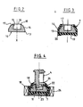
- the tap shown in FIG. 1 firstly comprises a body 1 of conventional shape, onto which a head 2 carrying a shutter 3 is fixed by screwing.
- This shutter 3 comprises a control rod 4 which passes tightly through the head 2 and slides by screwing into it thanks to a threaded part 5.
- the control rod 4 At its end external to the body t, the control rod 4 is provided with an operating handle 6, while at its free end situated at the inside the body 1, it carries a rubber valve 7, intended to cooperate with a seat 8 bordering the orifice 9 through which the fluid stream passes.
- the valve 7 is supported by a valve-carrying element 10 rotatably mounted around a shoulder defined by a circular flange 11 formed at the very end of the free end of the control rod 4.
- the valve-holder element 10 is constituted by a pellet which covers the free end of the control rod 4 by closing with a lip 12 on the flange 11 of the latter.
- this patch 10 has a cylindrical base 13 extended by a frustoconical part 14 and is provided with a blind recess 15 of circular section, centered around the axis of symmetry X of the patch and opening out by a opening 16 on the circular face 17 of the frusto-conical part 14.
- the patch 10 is made of polytetrafluoroethylene and, before being mounted on the rod, that is to say as shown in FIG. 2, it has a extra thickness 18 of this material, formed in relief on the face 17, author of the opening 16 of the recess 15.
- the valve 7 is molded around the pellet 10 before the latter is placed on the rod 4.
- This molding is carried out in a completely conventional manner using a mold (not shown) in two parts whose joint plane is located at the base 13 of the pad 10 perpendicular to the axis X thereof. As shown in FIG. 3, this molding is carried out in such a way that the valve 7 completely envelops the base 13 of the patch 10 as well as the frustoconical part 14 thereof, up to the edge of its circular face 17.
- control rod 4 of the shutter 3 carries a second circular flange 21 of larger diameter than the first and defining therewith a groove 22 in which is housed the lip 12 of the wafer 10.
- the diameter of the flange is moreover substantially equal to that of the face 17 of the wafer 10.
- the pad 10 coated with the valve 7 is fitted into a shoe 23 coupled to an ultrasonic wave generator 24.
- the control rod 4 is then introduced by its free end carrying the flange 11, in the recess 15 in the patch 10, until its second flange 21 comes into contact with the additional thickness 18.
- the generator 24 is put into service which applies to the patch 10 of the ultrasonic waves through the wall of the shoe 23 and the rubber of the valve 7.
- the polytetrafluoroethylene will flow at the level of the extra thickness 18 to form around the opening 16 of the patch 10, the lip 12 which is automatically housed inside the groove 22.
- the 10-valve 7 disc assembly is perfectly retained in rotation at the free end of the control rod 4. This rotation is further favored by the fact that the pad 10 is made of polytetrafluoroethylene and that the valve 7 closes around the flange 21 thereby preventing the formation of calcareous deposits in the area of contact of the pellet with the stem.
Landscapes
- Engineering & Computer Science (AREA)
- General Engineering & Computer Science (AREA)
- Mechanical Engineering (AREA)
- Lift Valve (AREA)
Abstract
Description
La présente invention se rapporte à un robinet à clapet, du type comprenant un obturateur formé d'une tige de commande coulissant dans le corps du robinet et d'un clapet en matière souple monté à l'extrémité libre de la tige de commande pour coopérer avec un siège aménagé à l'intérieur du corps sur le trajet de la veine fluide, ce clapet étant porté par un élément libre en rotation qui prend appui contre un épaulement de la tige de commande.The present invention relates to a globe valve, of the type comprising a shutter formed by a control rod sliding in the body of the valve and by a flexible material valve mounted at the free end of the control rod to cooperate. with a seat arranged inside the body on the path of the fluid stream, this valve being carried by a free rotating element which bears against a shoulder of the control rod.
Dans les robinets connus de ce type, utilisés essentiellement comme robinets d'arrêt, de puisage ou d'arrosage, l'élément porte-clapet est constitué par un disque que l'on monte en rotation autour de la tige de commande avant de le pourvoir du clapet. En général, pour réaliser cet assemblage, on moule le clapet en caoutchouc ou, autre matière souple directement autour de l'extrémité libre de la tige de commande, de telle manière qu'il enveloppe tout à la fois le disque porte-clapet et l'épaulement contre lequel celui-ci prend appui.In known taps of this type, used essentially as stop, drawing or sprinkling taps, the valve-holder element consists of a disc which is mounted in rotation around the control rod before it provide the valve. In general, to achieve this assembly, the rubber valve or other flexible material is molded directly around the free end of the control rod, in such a way that it envelops both the valve carrier disk and the 'shoulder against which it is supported.
On connaît les avantages procurés par ce mode de formage du clapet qui simplifie grandement le montage en rotation du disque porte-clapet, élimine les vibrations au niveau du clapet et permet d'assurer une bonne étanchéité entre la veine fluide et le mécanisme de manoeuvre de la tige logé dans la tête du robinet, lorsque le clapet est en position d'ouverture totale.We know the advantages of this method of forming the valve which greatly simplifies the mounting in rotation of the valve disc, eliminates vibrations at the valve and ensures a good seal between the fluid stream and the operating mechanism. the rod housed in the valve head, when the valve is in the fully open position.
Toutefois, cette opération de moulage direct du clapet autour de l'extrémité libre de la tige de commande n'est pas totalement satisfaisante en ce sens qu'elle est, d'une part, rendue compliquée et relativement longue par le fait qu'elle doit être réalisée de part et d'autre de la tige et que, d'autre part, elle produit le long du plan de joint du moule, c'est-à-dire dans un plan longitudinal de la tige de commande,une bavure qui court notamment à travers la face de contact du clapet avec le siège et risque donc d'affecter l'étanchéité entre ces derniers dans la position de fermeture du clapet.However, this direct molding operation of the valve around the free end of the control rod is not entirely satisfactory in the sense that it is, on the one hand, made complicated and relatively long by the fact that it must be made on both sides of the rod and that, on the other hand, it produces along the joint plane of the mold, that is to say in a longitudinal plane of the control rod, a burr which runs in particular through the contact face of the valve with the seat and therefore risks affecting the seal between the latter in the valve closed position.
Un autre inconvénient de cette opération de moulage réside dans le fait que si elle conduit à un résultat défectueux, et c'est souvent le cas lors du moulage du caoutchouc sur du laiton, métal dont est faite en général la tige de commande, il faut mettre au rebut l'obturateur tout entier, c'est-à-dire ses trois composants à la fois.Another drawback of this molding operation lies in the fact that if it leads to a defective result, and this is often the case when molding rubber on brass, the metal of which the control rod is generally made, it is necessary discard the entire shutter, that is, all three components at once.
La présente invention se propose de remédier à ces inconvénients et, pour ce faire, elle a pour objet un robinet du type spécifié en préambule qui se caractérise en ce que son élément porte-clapet est constitué par une pastille d'une certaine hauteur coiffant l'extrémité libre de la tige de commande en se refermant sur l'épaulement de cette dernière.The present invention proposes to remedy these drawbacks and, to do this, it relates to a tap of the type specified in the preamble which is characterized in that its valve-holder element consists of a pellet of a certain height covering the free end of the control rod by closing on the shoulder of the latter.
Plus précisément, la pastille coiffe l'extrémité libre de la tige de commande par un évidement borgne dans lequel l'épaulement de cette dernière est logé, et se referme sur celui-ci par une lèvre qui s'avance à l'intérieur de cet évidement.More specifically, the pellet covers the free end of the control rod by a blind recess in which the shoulder of the latter is housed, and closes thereon by a lip which advances inside this obviously.
Ainsi, pour fabriquer l'obturateur d'un tel robinet, on peut, selon un procédé qui fait également l'objet de la présente invention, commencer par mettre en place, et en particulier mouler, le clapet autour de la pastille dont on coiffe ensuite l'extrémité libre de la tige de commande en agissant de telle manière qu'elle se referme sur l'épaulement de cette dernière.Thus, to manufacture the shutter of such a tap, it is possible, according to a process which is also the subject of the present invention, to start by putting in place, and in particular molding, the valve around the pellet which is topped then the free end of the control rod by acting in such a way that it closes on the shoulder of the latter.
Plus précisément, on part d'une pastille dont l'évidement présente une paroi lisse sur toute sa hauteur et qui est faite d'une matière apte à se déformer sous l'effet d'une sollicitation extérieure appropriée et, après avoir mis en place le clapet sur la pastille, on introduit l'extrémité libre de la tige de commande dans cet évidement avant de déformer la pastille au-dessus du premier épaulement pour former la lèvre refermant la pastille sur ce dernier.More specifically, we start from a pellet whose recess has a smooth wall over its entire height and which is made of a material capable of deforming under the effect of an appropriate external stress and, after having put in place the valve on the wafer, the free end of the control rod is introduced into this recess before deforming the wafer above the first shoulder to form the lip closing the wafer on the latter.
Comme on le comprendra aisément, le moulage du clapet sur la pastille, avant le montage de celle-ci sur la tige de commande, est grandement simplifié par rapport au moulage conventionnel effectué de part et d'autre de cette dernière. Il permet en outre l'utilisation d'un moule dont le pian de joint ne traverse pas la face de contact du clapet avec son siège et qui produit donc un clapet exempt de bavure dans sa partie fonctionnelle, ce clapet offrant ainsi tontes les garanties d'étanchéité en position fermée.As will be readily understood, the molding of the valve on the wafer, before mounting it on the control rod, is greatly simplified compared to the conventional molding carried out on either side of the latter. It also allows the use of a mold, the joint plane of which does not cross the contact face of the valve with its seat and which therefore produces a valve free of burrs in its functional part, this valve thus offering all the guarantees of sealing in closed position.
On notera ici que le fait de réaliser l'opération d'assemblage de l'obturateur en deux étapes, et non plus en une seule comme précédemment, ne constitue pas un handicap en ce qui concerne la durée de cette opération, puisque chaque clapet peut être moulé sur sa pastille pendant que l'on monte une autre pastille déjà pourvue de son clapet sur sa tige de commande.It will be noted here that the fact of carrying out the assembly operation of the shutter in two stages, and no longer in a single one as previously, does not constitute a handicap as regards the duration of this operation, since each valve can be molded on its pellet while mounting another pellet already provided with its valve on its control rod.
Selon un mode d'exécution préféré du procédé objet de la présente invention, on utilise une pastille faite d'une matière plastique apte à subir un fluage sous l'application d'ondes ultra-sonores et présentant une surépaisseur autour de l'ouverture de son évidement et on forme la lèvre en soumettant la pastille à des ondes ultra-sonores.According to a preferred embodiment of the method which is the subject of the present invention, a pellet made of a plastic material capable of undergoing creep under the application of ultrasonic waves and having an extra thickness around the opening of a its recess and the lip is formed by subjecting the pellet to ultrasonic waves.
L'expérience montre que cette opération d'assemblage par les ultra-sons peut être exécutée presque instantanément. Si on ajoute à cela qu'elle peut facilement être automatisée à l'aide d'un équipement simple et peu onéreux, travaillant à cadence élevée et que la pastille en matière plastique est moins coûteuse que le disque en laiton utilisé jusqu'à présent, le procédé selon l'invention conduit à une réduction non négligeable du coût de fabrication des obturateurs de robinets à clapet.Experience shows that this assembly operation by ultrasound can be performed almost instantly. If we add to this that it can easily be automated using simple and inexpensive equipment, working at high speed and that the plastic pad is less expensive than the brass disc used until now, the method according to the invention leads to a non-negligible reduction in the cost of manufacturing the shutters of flap valves.
Il est encore à noter que le moulage du caoutchouc sur de la matière plastique est bien plus fiable que sur du laiton, ce qui confère un avantage supplémentaire au procédé selon l'invention. De toute façon, même si le moulage du clapet sur la pastille venait à présenter un défaut, on n'aurait à mettre au rebut que l'ensemble clapet-pastille et non pas l'ooturateur tout entier.It should also be noted that the molding of rubber on plastic is much more reliable than on brass, which gives an additional advantage to the process according to the invention. In any case, even if the molding of the valve on the pellet were to present a defect, we would have to discard only the valve-pellet assembly and not the entire ooturator.
On ajoutera encore que, pour réaliser la pastille, on utilise de préférence du polytétrafluoroéthylène, qui outre le fait qu'il est tout particulièrement bien adapté pour subir un fluage sous l'effet des ondes ultra-sonores, présente un faible coefficient de frottement sur le métal, qui favorisera la rotation de la pastille autour de la tige de commande.It will also be added that, in order to produce the pellet, polytetrafluoroethylene is preferably used, which, in addition to the fact that it is very particularly suitable for undergoing creep under the effect of ultrasonic waves, has a low coefficient of friction on metal, which will favor the rotation of the pellet around the control rod.
Selon une autre caractéristique de l'invention, on peut pourvoir la tige de commande de l'obturateur d'un deuxième épaulement qui délimite avec le premier une gorge dans laquelle est logée la lèvre de la pastille. De la sorte, le mouvement axial de la pastille par rapport à la tige sera fortement limité voire même réduit à néant et en conséquence, les vibrations du clapet en position ouverte peuvent être éliminées.According to another characteristic of the invention, the control rod of the shutter can be provided with a second shoulder which defines with the first a groove in which the lip of the pellet is housed. In this way, the axial movement of the pellet relative to the rod will be greatly limited or even reduced to nothing and consequently, the vibrations of the valve in the open position can be eliminated.
En outre, le clapet est de préférence moulé autour de la pastille de manière à se refermer autour du deuxième épaulement de la tige de l'obturateur, pour ainsi obturer l'évidement de la pastille et empêcher la formation dans celui-ci de dépôts calcaires qui pourraient entraver la rotation de la pastille.In addition, the valve is preferably molded around the pellet so as to close around the second shoulder of the shutter rod, thereby closing the recess of the pellet and preventing the formation in it of lime deposits. which could hinder the rotation of the tablet.
Avantageusement,'la pastille présente une partie tronconique qui se rétrécit en direction de l'ouverture de son évidement, le clapet étant moulé de manière à recouvrir entièrement cette partie tronconique. De la sorte, le clapet est retenu en toute fiabilité sur la pastille et, lorsqu'il est en position d'ouverture totale, il assure en outre, tout comme les clapets existants, l'étanchéité du mécanisme de manoeuvre de l'obturateur logé dans la tête du robinet.Advantageously, the tablet has a frustoconical part which narrows in the direction of the opening of its recess, the valve being molded so as to completely cover this frustoconical part. In this way, the valve is reliably retained on the pellet and, when in the fully open position, it also ensures, like the existing valves, the tightness of the operating mechanism of the shutter housed in the tap head.
Enfin, le premier épaulement de la tige de commande est défini par une collerette formée au bout de l'extrémité libre de cette dernière, cette collerette exerçant une pression uniformément répartie sur le fond de l'évidement de la pastille lorsque le clapet est placé en appui contre son siège.Finally, the first shoulder of the control rod is defined by a flange formed at the end of the free end of the latter, this flange exerting a pressure uniformly distributed over the bottom of the recess of the pellet when the valve is placed in abutment against its seat.
Un mode de réalisation de la présente invention va maintenant être décrit uniquement à titre d'exemple non limitatif en référence aux dessins annexés dans lesquels :
- - la figure 1 est une vue simplifiée en coupe longitudinale partielle d'un robinet à clapet conforme à l'invention ;
- - les figures 2 et 3 sont des vues en coupe longitudinale de la pastille porte-clapet avant et après le moulage du clapet ; et
- - la figure 4 est une vue en coupe illustrant le montage de la pastille sur la tige de commande de l'obturateur.
- - Figure 1 is a simplified view in partial longitudinal section of a flap valve according to the invention;
- - Figures 2 and 3 are views in longitudinal section of the valve holder disc before and after molding the valve; and
- - Figure 4 is a sectional view illustrating the mounting of the patch on the shutter control rod.
Le robinet représenté sur la figure 1 comprend tout d'abord un corps 1 de forme classique, sur lequel vient se fixer par vissage une tête 2 portant un obturateur 3. Cet obturateur 3 comprend une tige de commande 4 qui traverse de manière étanche la tête 2 et coulisse par vissage dans celle-ci grâce à une partie filetée 5. A son extrémité extérieure au corps t, la tige de commande 4 est pourvue d'une poignée de manoeuvre 6, tandis qu'à son extrémité libre située à l'intérieur du corps 1, elle porte un clapet 7 en caoutchouc, destiné à coopérer avec un siège 8 bordant l'orifice 9 par lequel passe la veine fluide. Le clapet 7 est supporté par un élément porte-clapet 10 monté à rotation autour d'un épaulement défini par une collerette circulaire 11 formée tout au bout de l'extrémité libre de la tige de commande 4.The tap shown in FIG. 1 firstly comprises a body 1 of conventional shape, onto which a head 2 carrying a
Selon la caractéristique première de l'invention, l'élément porte-clapet 10 est constitué par une pastille qui vient coiffer l'extrémité libre de la tige de commande 4 en se refermant par une lèvre 12 sur la collerette 11 de cette dernière.According to the first characteristic of the invention, the valve-
Comme le montre la figure 2, cette pastille 10 comporte une base cylindrique 13 prolongée par une partie tronconique 14 et est pourvue d'un évidement borgne 15 de section circulaire, centré autour de l'axe de symétrie X de la pastille et débouchant par une ouverture 16 sur la face circulaire 17 de la partie tronconique 14. La pastille 10 est faite en polytétrafluoroéthylène et, avant son montage sur la tige, c'est-à-dire telle qu'elle est représentée sur la figure 2, elle présente une surépaisseur 18 de cette matière, formée en relief sur la face 17, auteur de l'ouverture 16 de l'évidement 15.As shown in FIG. 2, this
Selon une autre caractéristique de l'invention, le clapet 7 est moulé autour de la pastille 10 avant que celle-ci ne soit mise en place sur la tige 4. Ce moulage est effectué de façon tout à fait classique à l'aide d'un moule (non représenté) en deux parties dont le plan de joint se situe à hauteur de la base 13 de la pastille 10 perpendiculairement à l'axe X de celle-ci. Comme le montre la figure 3, on exécute ce moulage de telle façon que le clapet 7 enveloppe entièrement la base 13 de la pastille 10 ainsi que la partie tronconique 14 de celle-ci, jusqu'au bord de sa face circulaire 17. En outre, lors de ce moulage, on fait en sorte que le clapet 7 présente une plus grande épaisseur sur sa face 19 destinée à venir en contact avec le siège 8 que sur sa face latérale, afin qu'il puisse jouer à cet endroit le rôle d'un amortisseur. Cet effet peut être renforcé par un bourrelet 20 formé sur la circonférence de cette face 19.According to another characteristic of the invention, the
En revenant à la figure 1, on peut voir que la tige de commande 4 de l'obturateur 3 porte une seconde collerette circulaire 21 de plus grand diamètre que la première et délimitant avec celle-ci une gorge 22 dans laquelle est logée la lèvre 12 de la pastille 10. Le diamètre de la collerette est en outre sensiblement égal à celui de la face 17 de la pastille 10. '-Le montage de l'ensemble pastille 10-clapet 7, représenté sur la figure 2, autour de l'extrémité libre de la tige de commande 4, va maintenant être décrit en référence à la figure 4.Returning to Figure 1, we can see that the
Dans un premier temps, la pastille 10 revêtue du clapet 7 est emboîtée dans un sabot 23 accouplé à un générateur d'ondes ultra-sonores 24. La tige de commande 4 est alors introduite par son extrémité libre portant la collerette 11, dans l'évidement 15 de la pastille 10, jusqu'à ce que sa seconde collerette 21 vienne au contact de la surépaisseur 18. Puis, la tige 4 étant maintenue dans cette position par des moyens non représentés, on met en service le générateur 24 qui applique sur la pastille 10 des ondes ultra-sonores à travers la paroi du sabot 23 et le caoutchouc du clapet 7. Sous l'action conjuguée des vibrations et de l'énergie thermique engendrées par ces ondes ultra-sonores, le polytétrafluoroéthylène va fluer au niveau de la surépaisseur 18 pour former autour de l'ouverture 16 de la pastille 10, la lèvre 12 qui vient se loger automatiquement à l'intérieur de la gorge 22.Initially, the
Il va de soi que la succession d'opérations qui vient d'être décrite peut être automatisée et donc exécutée en un laps de temps très bref.It goes without saying that the succession of operations which has just been described can be automated and therefore executed in a very short period of time.
A la fin de de montage, l'ensemble pastille 10-clapet 7 est parfaitement retenu en rotation à l'extrémité libre de la tige de commande 4. Cette rotation est en outre favorisée par le fait que la pastille 10 est en polytétrafluoroéthylène et que le clapet 7 se referme autour de la collerette 21 en empêchant ainsi la formation de dépôts calcaires au niveau de la zone de contact de la pastille avec la tige.At the end of assembly, the 10-
Claims (9)
Applications Claiming Priority (2)
| Application Number | Priority Date | Filing Date | Title |
|---|---|---|---|
| FR8415146 | 1984-10-03 | ||
| FR8415146A FR2571116B1 (en) | 1984-10-03 | 1984-10-03 | IMPROVED VALVE VALVE AND METHOD FOR MANUFACTURING THE SHUTTER OF SUCH A VALVE |
Publications (1)
| Publication Number | Publication Date |
|---|---|
| EP0178221A1 true EP0178221A1 (en) | 1986-04-16 |
Family
ID=9308292
Family Applications (1)
| Application Number | Title | Priority Date | Filing Date |
|---|---|---|---|
| EP85401918A Withdrawn EP0178221A1 (en) | 1984-10-03 | 1985-10-02 | Lift valve and method for manufacturing such a valve |
Country Status (2)
| Country | Link |
|---|---|
| EP (1) | EP0178221A1 (en) |
| FR (1) | FR2571116B1 (en) |
Citations (6)
| Publication number | Priority date | Publication date | Assignee | Title |
|---|---|---|---|---|
| BE473506A (en) * | 1943-06-18 | |||
| CH114339A (en) * | 1925-04-09 | 1926-05-01 | Jules Clarion | Tap. |
| GB875446A (en) * | 1956-11-12 | 1961-08-23 | Baltzar Carl Von Platen | Improvements in or relating to cocks |
| FR2084395A5 (en) * | 1970-03-05 | 1971-12-17 | Lucas Industries Ltd | |
| FR2253960A1 (en) * | 1973-12-07 | 1975-07-04 | Utsue Valve Co Ltd | Locking device for fixing a valve to its stem - collar and end of stem fit within recess of the valve |
| FR2315048A1 (en) * | 1975-06-16 | 1977-01-14 | Huot Sa | Tap with flexible closure member - moulded onto annular disc and enveloping shoulder on stem |
Family Cites Families (1)
| Publication number | Priority date | Publication date | Assignee | Title |
|---|---|---|---|---|
| BE473508A (en) * |
-
1984
- 1984-10-03 FR FR8415146A patent/FR2571116B1/en not_active Expired
-
1985
- 1985-10-02 EP EP85401918A patent/EP0178221A1/en not_active Withdrawn
Patent Citations (6)
| Publication number | Priority date | Publication date | Assignee | Title |
|---|---|---|---|---|
| CH114339A (en) * | 1925-04-09 | 1926-05-01 | Jules Clarion | Tap. |
| BE473506A (en) * | 1943-06-18 | |||
| GB875446A (en) * | 1956-11-12 | 1961-08-23 | Baltzar Carl Von Platen | Improvements in or relating to cocks |
| FR2084395A5 (en) * | 1970-03-05 | 1971-12-17 | Lucas Industries Ltd | |
| FR2253960A1 (en) * | 1973-12-07 | 1975-07-04 | Utsue Valve Co Ltd | Locking device for fixing a valve to its stem - collar and end of stem fit within recess of the valve |
| FR2315048A1 (en) * | 1975-06-16 | 1977-01-14 | Huot Sa | Tap with flexible closure member - moulded onto annular disc and enveloping shoulder on stem |
Also Published As
| Publication number | Publication date |
|---|---|
| FR2571116B1 (en) | 1987-02-20 |
| FR2571116A1 (en) | 1986-04-04 |
Similar Documents
| Publication | Publication Date | Title |
|---|---|---|
| EP0139712B1 (en) | Method for assembling a plurality of members, particularly connection members for fluid connectors | |
| EP0538094B1 (en) | Metal container which can be partially opened by tearing along a line of weakness | |
| EP0440564B1 (en) | Device for connecting a hose end to a rigid pipe end | |
| EP0161980A2 (en) | Make-up assembly, in particular for eye-lashes, for the use of a predetermined amount of make-up product | |
| FR2688860A1 (en) | Leaktight (sealed) drainage member for hydraulic circuit | |
| FR2779040A1 (en) | DEVICE FOR DISPENSING PASTE PRODUCT, ESPECIALLY COSMETIC, AND METHOD FOR MANUFACTURING THE DEVICE | |
| FR2504638A1 (en) | BUTTERFLY VALVE WITH COATED BODY | |
| FR2734039A1 (en) | PERFECTED VALVE FOR PACKAGING AND DISTRIBUTION DEVICE FOR A PRODUCT STORED UNDER PRESSURE, DEVICE THUS EQUIPPED AND MANUFACTURING PROCESS | |
| FR2856529A1 (en) | WATERPROOF WALL THROUGH DEVICE. | |
| FR2564935A1 (en) | RETENTION VALVE FOR LIQUID OR AERIFORM FLUIDS | |
| EP0292346B1 (en) | Sealing element incorporating a reaction ring, especially for a stop valve | |
| FR2559231A1 (en) | Sealing ring for shaft | |
| FR2571116A1 (en) | IMPROVED VALVE VALVE AND METHOD OF MANUFACTURING THE SHUTTER OF SUCH FAUCET | |
| FR2594520A1 (en) | ROD END SEAL FOR STOP VALVE | |
| WO2007077361A2 (en) | Nozzle for dispensing a fluid product, dispensing device comprising such a nozzle and method of manufacture | |
| EP1802402B1 (en) | Securing method, manufacturing method, and secure spraying endpiece | |
| FR2653643A1 (en) | Stick for applying a pasty product | |
| EP1094372B1 (en) | Control knob | |
| EP0202156A1 (en) | Anular sealing device, especially for valves or taps | |
| FR2594205A1 (en) | End connector for a flexible pipe | |
| CA2025066C (en) | Mounting device for friction pad on a valve disc | |
| FR2923329A1 (en) | Electrical cable sealing and passing device for electrical tubular motor, has sealing plug to seal section of passage with respect to terminal end, where passage from insertion to sealing positions comprises pivot movement from plug to end | |
| FR2656073A1 (en) | Air guide duct with a flap | |
| FR2712633A1 (en) | Bleeding device for e.g. IC engine coolant hoses | |
| WO1991014109A1 (en) | Rapid-assembly protective bellows for universal joints |
Legal Events
| Date | Code | Title | Description |
|---|---|---|---|
| PUAI | Public reference made under article 153(3) epc to a published international application that has entered the european phase |
Free format text: ORIGINAL CODE: 0009012 |
|
| AK | Designated contracting states |
Kind code of ref document: A1 Designated state(s): AT BE CH DE GB IT LI LU NL SE |
|
| 17P | Request for examination filed |
Effective date: 19861008 |
|
| STAA | Information on the status of an ep patent application or granted ep patent |
Free format text: STATUS: THE APPLICATION HAS BEEN WITHDRAWN |
|
| 18W | Application withdrawn |
Withdrawal date: 19871009 |
|
| RIN1 | Information on inventor provided before grant (corrected) |
Inventor name: DUMEZ, ROGER |