EP0178221A1 - Hebeventil und Verfahren zum Herstellen eines solchen Ventils - Google Patents
Hebeventil und Verfahren zum Herstellen eines solchen Ventils Download PDFInfo
- Publication number
- EP0178221A1 EP0178221A1 EP85401918A EP85401918A EP0178221A1 EP 0178221 A1 EP0178221 A1 EP 0178221A1 EP 85401918 A EP85401918 A EP 85401918A EP 85401918 A EP85401918 A EP 85401918A EP 0178221 A1 EP0178221 A1 EP 0178221A1
- Authority
- EP
- European Patent Office
- Prior art keywords
- valve
- control rod
- pellet
- shoulder
- free end
- Prior art date
- Legal status (The legal status is an assumption and is not a legal conclusion. Google has not performed a legal analysis and makes no representation as to the accuracy of the status listed.)
- Withdrawn
Links
- 238000000034 method Methods 0.000 title claims abstract description 18
- 238000004519 manufacturing process Methods 0.000 title claims abstract description 5
- 239000008188 pellet Substances 0.000 claims abstract description 32
- 239000000463 material Substances 0.000 claims abstract description 11
- 229920001343 polytetrafluoroethylene Polymers 0.000 claims abstract description 6
- 239000004810 polytetrafluoroethylene Substances 0.000 claims abstract description 6
- 239000012530 fluid Substances 0.000 claims description 5
- -1 polytetrafluoroethylene Polymers 0.000 claims description 5
- 230000008569 process Effects 0.000 claims description 4
- 230000015572 biosynthetic process Effects 0.000 claims description 3
- 239000004033 plastic Substances 0.000 abstract description 5
- 238000000465 moulding Methods 0.000 description 12
- 229910001369 Brass Inorganic materials 0.000 description 3
- 239000010951 brass Substances 0.000 description 3
- 230000000694 effects Effects 0.000 description 3
- 230000008901 benefit Effects 0.000 description 2
- 230000007246 mechanism Effects 0.000 description 2
- 239000002184 metal Substances 0.000 description 2
- 235000010603 pastilles Nutrition 0.000 description 2
- 230000000717 retained effect Effects 0.000 description 2
- 235000008733 Citrus aurantifolia Nutrition 0.000 description 1
- 235000011941 Tilia x europaea Nutrition 0.000 description 1
- 239000006096 absorbing agent Substances 0.000 description 1
- 230000009471 action Effects 0.000 description 1
- 239000011324 bead Substances 0.000 description 1
- 230000007547 defect Effects 0.000 description 1
- 230000002950 deficient Effects 0.000 description 1
- 230000006355 external stress Effects 0.000 description 1
- 239000004571 lime Substances 0.000 description 1
- 230000009467 reduction Effects 0.000 description 1
- 238000007789 sealing Methods 0.000 description 1
- 230000035939 shock Effects 0.000 description 1
- 238000002604 ultrasonography Methods 0.000 description 1
Images

Classifications
-
- F—MECHANICAL ENGINEERING; LIGHTING; HEATING; WEAPONS; BLASTING
- F16—ENGINEERING ELEMENTS AND UNITS; GENERAL MEASURES FOR PRODUCING AND MAINTAINING EFFECTIVE FUNCTIONING OF MACHINES OR INSTALLATIONS; THERMAL INSULATION IN GENERAL
- F16K—VALVES; TAPS; COCKS; ACTUATING-FLOATS; DEVICES FOR VENTING OR AERATING
- F16K1/00—Lift valves or globe valves, i.e. cut-off apparatus with closure members having at least a component of their opening and closing motion perpendicular to the closing faces
- F16K1/32—Details
- F16K1/48—Attaching valve members to screw-spindles
- F16K1/482—Attaching valve members to screw-spindles with a collar on the spindle or a groove in the spindle, by which a fixing element is supported, the spindle reaching into the valve member
Definitions
- the present invention relates to a globe valve, of the type comprising a shutter formed by a control rod sliding in the body of the valve and by a flexible material valve mounted at the free end of the control rod to cooperate. with a seat arranged inside the body on the path of the fluid stream, this valve being carried by a free rotating element which bears against a shoulder of the control rod.
- valve-holder element In known taps of this type, used essentially as stop, drawing or sprinkling taps, the valve-holder element consists of a disc which is mounted in rotation around the control rod before it provide the valve. In general, to achieve this assembly, the rubber valve or other flexible material is molded directly around the free end of the control rod, in such a way that it envelops both the valve carrier disk and the 'shoulder against which it is supported.
- the present invention proposes to remedy these drawbacks and, to do this, it relates to a tap of the type specified in the preamble which is characterized in that its valve-holder element consists of a pellet of a certain height covering the free end of the control rod by closing on the shoulder of the latter.
- the pellet covers the free end of the control rod by a blind recess in which the shoulder of the latter is housed, and closes thereon by a lip which advances inside this obviously.
- the molding of the valve on the wafer, before mounting it on the control rod is greatly simplified compared to the conventional molding carried out on either side of the latter. It also allows the use of a mold, the joint plane of which does not cross the contact face of the valve with its seat and which therefore produces a valve free of burrs in its functional part, this valve thus offering all the guarantees of sealing in closed position.
- a pellet made of a plastic material capable of undergoing creep under the application of ultrasonic waves and having an extra thickness around the opening of a its recess and the lip is formed by subjecting the pellet to ultrasonic waves.
- polytetrafluoroethylene is preferably used, which, in addition to the fact that it is very particularly suitable for undergoing creep under the effect of ultrasonic waves, has a low coefficient of friction on metal, which will favor the rotation of the pellet around the control rod.
- control rod of the shutter can be provided with a second shoulder which defines with the first a groove in which the lip of the pellet is housed.
- valve is preferably molded around the pellet so as to close around the second shoulder of the shutter rod, thereby closing the recess of the pellet and preventing the formation in it of lime deposits. which could hinder the rotation of the tablet.
- the tablet has a frustoconical part which narrows in the direction of the opening of its recess, the valve being molded so as to completely cover this frustoconical part.
- the valve is reliably retained on the pellet and, when in the fully open position, it also ensures, like the existing valves, the tightness of the operating mechanism of the shutter housed in the tap head.
- the first shoulder of the control rod is defined by a flange formed at the end of the free end of the latter, this flange exerting a pressure uniformly distributed over the bottom of the recess of the pellet when the valve is placed in abutment against its seat.
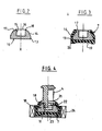
- the tap shown in FIG. 1 firstly comprises a body 1 of conventional shape, onto which a head 2 carrying a shutter 3 is fixed by screwing.
- This shutter 3 comprises a control rod 4 which passes tightly through the head 2 and slides by screwing into it thanks to a threaded part 5.
- the control rod 4 At its end external to the body t, the control rod 4 is provided with an operating handle 6, while at its free end situated at the inside the body 1, it carries a rubber valve 7, intended to cooperate with a seat 8 bordering the orifice 9 through which the fluid stream passes.
- the valve 7 is supported by a valve-carrying element 10 rotatably mounted around a shoulder defined by a circular flange 11 formed at the very end of the free end of the control rod 4.
- the valve-holder element 10 is constituted by a pellet which covers the free end of the control rod 4 by closing with a lip 12 on the flange 11 of the latter.
- this patch 10 has a cylindrical base 13 extended by a frustoconical part 14 and is provided with a blind recess 15 of circular section, centered around the axis of symmetry X of the patch and opening out by a opening 16 on the circular face 17 of the frusto-conical part 14.
- the patch 10 is made of polytetrafluoroethylene and, before being mounted on the rod, that is to say as shown in FIG. 2, it has a extra thickness 18 of this material, formed in relief on the face 17, author of the opening 16 of the recess 15.
- the valve 7 is molded around the pellet 10 before the latter is placed on the rod 4.
- This molding is carried out in a completely conventional manner using a mold (not shown) in two parts whose joint plane is located at the base 13 of the pad 10 perpendicular to the axis X thereof. As shown in FIG. 3, this molding is carried out in such a way that the valve 7 completely envelops the base 13 of the patch 10 as well as the frustoconical part 14 thereof, up to the edge of its circular face 17.
- control rod 4 of the shutter 3 carries a second circular flange 21 of larger diameter than the first and defining therewith a groove 22 in which is housed the lip 12 of the wafer 10.
- the diameter of the flange is moreover substantially equal to that of the face 17 of the wafer 10.
- the pad 10 coated with the valve 7 is fitted into a shoe 23 coupled to an ultrasonic wave generator 24.
- the control rod 4 is then introduced by its free end carrying the flange 11, in the recess 15 in the patch 10, until its second flange 21 comes into contact with the additional thickness 18.
- the generator 24 is put into service which applies to the patch 10 of the ultrasonic waves through the wall of the shoe 23 and the rubber of the valve 7.
- the polytetrafluoroethylene will flow at the level of the extra thickness 18 to form around the opening 16 of the patch 10, the lip 12 which is automatically housed inside the groove 22.
- the 10-valve 7 disc assembly is perfectly retained in rotation at the free end of the control rod 4. This rotation is further favored by the fact that the pad 10 is made of polytetrafluoroethylene and that the valve 7 closes around the flange 21 thereby preventing the formation of calcareous deposits in the area of contact of the pellet with the stem.
Landscapes
- Engineering & Computer Science (AREA)
- General Engineering & Computer Science (AREA)
- Mechanical Engineering (AREA)
- Lift Valve (AREA)
Applications Claiming Priority (2)
| Application Number | Priority Date | Filing Date | Title |
|---|---|---|---|
| FR8415146 | 1984-10-03 | ||
| FR8415146A FR2571116B1 (fr) | 1984-10-03 | 1984-10-03 | Robinet a clapet perfectionne et procede de fabrication de l'obturateur d'un tel robinet |
Publications (1)
| Publication Number | Publication Date |
|---|---|
| EP0178221A1 true EP0178221A1 (de) | 1986-04-16 |
Family
ID=9308292
Family Applications (1)
| Application Number | Title | Priority Date | Filing Date |
|---|---|---|---|
| EP85401918A Withdrawn EP0178221A1 (de) | 1984-10-03 | 1985-10-02 | Hebeventil und Verfahren zum Herstellen eines solchen Ventils |
Country Status (2)
| Country | Link |
|---|---|
| EP (1) | EP0178221A1 (de) |
| FR (1) | FR2571116B1 (de) |
Citations (6)
| Publication number | Priority date | Publication date | Assignee | Title |
|---|---|---|---|---|
| BE473506A (de) * | 1943-06-18 | |||
| CH114339A (fr) * | 1925-04-09 | 1926-05-01 | Jules Clarion | Robinet. |
| GB875446A (en) * | 1956-11-12 | 1961-08-23 | Baltzar Carl Von Platen | Improvements in or relating to cocks |
| FR2084395A5 (de) * | 1970-03-05 | 1971-12-17 | Lucas Industries Ltd | |
| FR2253960A1 (en) * | 1973-12-07 | 1975-07-04 | Utsue Valve Co Ltd | Locking device for fixing a valve to its stem - collar and end of stem fit within recess of the valve |
| FR2315048A1 (fr) * | 1975-06-16 | 1977-01-14 | Huot Sa | Robinet a clapet perfectionne |
Family Cites Families (1)
| Publication number | Priority date | Publication date | Assignee | Title |
|---|---|---|---|---|
| BE473508A (de) * |
-
1984
- 1984-10-03 FR FR8415146A patent/FR2571116B1/fr not_active Expired
-
1985
- 1985-10-02 EP EP85401918A patent/EP0178221A1/de not_active Withdrawn
Patent Citations (6)
| Publication number | Priority date | Publication date | Assignee | Title |
|---|---|---|---|---|
| CH114339A (fr) * | 1925-04-09 | 1926-05-01 | Jules Clarion | Robinet. |
| BE473506A (de) * | 1943-06-18 | |||
| GB875446A (en) * | 1956-11-12 | 1961-08-23 | Baltzar Carl Von Platen | Improvements in or relating to cocks |
| FR2084395A5 (de) * | 1970-03-05 | 1971-12-17 | Lucas Industries Ltd | |
| FR2253960A1 (en) * | 1973-12-07 | 1975-07-04 | Utsue Valve Co Ltd | Locking device for fixing a valve to its stem - collar and end of stem fit within recess of the valve |
| FR2315048A1 (fr) * | 1975-06-16 | 1977-01-14 | Huot Sa | Robinet a clapet perfectionne |
Also Published As
| Publication number | Publication date |
|---|---|
| FR2571116B1 (fr) | 1987-02-20 |
| FR2571116A1 (fr) | 1986-04-04 |
Similar Documents
| Publication | Publication Date | Title |
|---|---|---|
| EP0139712B1 (de) | Verfahren zum verbinden mehrerer teile, insbesondere teilen von rohrverbindungsstücken | |
| EP0538094B1 (de) | Metallbehälter, der entlang einer Schwächungslinie teilweise geöffnet werden kann | |
| EP0440564B1 (de) | Vorrichtung zum Verbinden eines Schlauchendes mit dem Ende eines starren Rohres | |
| EP0161980A2 (de) | Schminkeinheit, insbesondere für Augenwimpern, die eine Entnahme einer vorherbestimmten Menge vom Schminkprodukt erlaubt | |
| FR2688860A1 (fr) | Organe de drainage etanche pour circuit hydraulique. | |
| FR2779040A1 (fr) | Dispositif distributeur de produit pateux notamment cosmetique et procede de fabrication de ce dispositif | |
| FR2504638A1 (fr) | Vanne papillon a corps revetu | |
| FR2734039A1 (fr) | Valve perfectionnee pour dispositif de conditionnement et de distribution d'un produit stocke sous pression, dispositif ainsi equipe et procede de fabrication | |
| FR2856529A1 (fr) | Dispositif de traversee etanche de paroi. | |
| FR2564935A1 (fr) | Soupape de retenue pour fluides liquides ou aeriformes | |
| EP0292346B1 (de) | Abdichtung mit eingebautem Reaktionsring, insbesondere für eine Absperrvorrichtung | |
| FR2559231A1 (fr) | Bague d'etancheite radiale pour arbre | |
| FR2571116A1 (fr) | Robinet a clapet perfectionne et procede de fabrication de l'obturateur d'un tel robinet | |
| FR2594520A1 (fr) | Joint de bout de tige pour robinet d'arret | |
| WO2007077361A2 (fr) | Buse de distribution de produit fluide, dispositif de distribution comprenant un telle buse et procede de fabrication | |
| EP1802402B1 (de) | Sicherungsverfahren, herstellungsverfahren und sicheres sprayendstück | |
| FR2653643A1 (fr) | Baton applicateur de produit pateux. | |
| EP1094372B1 (de) | Betätigungsknopf | |
| EP0202156A1 (de) | Ringförmige Dichtungsanordnung, insbesondere für Klappen oder Ventile | |
| FR2594205A1 (fr) | Raccord terminal de tuyau souple | |
| CA2025066C (fr) | Dispositif de fixation de pastilles de frottement sur un opercule de vanne | |
| FR2923329A1 (fr) | Dispositif d'obturation et de passage de cable electrique pour moteur tubulaire | |
| FR2656073A1 (fr) | Canal de guidage d'air avec un clapet. | |
| FR2712633A1 (fr) | Dispositif de purge d'un conduit de fluide. | |
| WO1991014109A1 (fr) | Soufflet de protection a montage rapide pour joints de transmission |
Legal Events
| Date | Code | Title | Description |
|---|---|---|---|
| PUAI | Public reference made under article 153(3) epc to a published international application that has entered the european phase |
Free format text: ORIGINAL CODE: 0009012 |
|
| AK | Designated contracting states |
Kind code of ref document: A1 Designated state(s): AT BE CH DE GB IT LI LU NL SE |
|
| 17P | Request for examination filed |
Effective date: 19861008 |
|
| STAA | Information on the status of an ep patent application or granted ep patent |
Free format text: STATUS: THE APPLICATION HAS BEEN WITHDRAWN |
|
| 18W | Application withdrawn |
Withdrawal date: 19871009 |
|
| RIN1 | Information on inventor provided before grant (corrected) |
Inventor name: DUMEZ, ROGER |