EP0177944A2 - Electrovanne bistable - Google Patents
Electrovanne bistable Download PDFInfo
- Publication number
- EP0177944A2 EP0177944A2 EP85112777A EP85112777A EP0177944A2 EP 0177944 A2 EP0177944 A2 EP 0177944A2 EP 85112777 A EP85112777 A EP 85112777A EP 85112777 A EP85112777 A EP 85112777A EP 0177944 A2 EP0177944 A2 EP 0177944A2
- Authority
- EP
- European Patent Office
- Prior art keywords
- armature
- solenoid valve
- membrane
- valve
- valve according
- Prior art date
- Legal status (The legal status is an assumption and is not a legal conclusion. Google has not performed a legal analysis and makes no representation as to the accuracy of the status listed.)
- Withdrawn
Links
- 239000012528 membrane Substances 0.000 claims abstract description 22
- 230000005484 gravity Effects 0.000 claims description 5
- 239000000463 material Substances 0.000 claims description 3
- 239000005300 metallic glass Substances 0.000 claims description 2
- 239000012530 fluid Substances 0.000 abstract description 19
- 230000004907 flux Effects 0.000 abstract description 2
- 238000009423 ventilation Methods 0.000 description 4
- XEEYBQQBJWHFJM-UHFFFAOYSA-N Iron Chemical compound [Fe] XEEYBQQBJWHFJM-UHFFFAOYSA-N 0.000 description 2
- PXHVJJICTQNCMI-UHFFFAOYSA-N Nickel Chemical compound [Ni] PXHVJJICTQNCMI-UHFFFAOYSA-N 0.000 description 2
- 229910045601 alloy Inorganic materials 0.000 description 2
- 239000000956 alloy Substances 0.000 description 2
- 238000010276 construction Methods 0.000 description 2
- 238000007789 sealing Methods 0.000 description 2
- ZOXJGFHDIHLPTG-UHFFFAOYSA-N Boron Chemical compound [B] ZOXJGFHDIHLPTG-UHFFFAOYSA-N 0.000 description 1
- OKTJSMMVPCPJKN-UHFFFAOYSA-N Carbon Chemical compound [C] OKTJSMMVPCPJKN-UHFFFAOYSA-N 0.000 description 1
- VYZAMTAEIAYCRO-UHFFFAOYSA-N Chromium Chemical compound [Cr] VYZAMTAEIAYCRO-UHFFFAOYSA-N 0.000 description 1
- ZOKXTWBITQBERF-UHFFFAOYSA-N Molybdenum Chemical compound [Mo] ZOKXTWBITQBERF-UHFFFAOYSA-N 0.000 description 1
- OAICVXFJPJFONN-UHFFFAOYSA-N Phosphorus Chemical compound [P] OAICVXFJPJFONN-UHFFFAOYSA-N 0.000 description 1
- XUIMIQQOPSSXEZ-UHFFFAOYSA-N Silicon Chemical compound [Si] XUIMIQQOPSSXEZ-UHFFFAOYSA-N 0.000 description 1
- 239000011324 bead Substances 0.000 description 1
- 230000005540 biological transmission Effects 0.000 description 1
- 229910052796 boron Inorganic materials 0.000 description 1
- 229910052799 carbon Inorganic materials 0.000 description 1
- 229910052804 chromium Inorganic materials 0.000 description 1
- 239000011651 chromium Substances 0.000 description 1
- 239000010941 cobalt Substances 0.000 description 1
- 229910017052 cobalt Inorganic materials 0.000 description 1
- GUTLYIVDDKVIGB-UHFFFAOYSA-N cobalt atom Chemical compound [Co] GUTLYIVDDKVIGB-UHFFFAOYSA-N 0.000 description 1
- 238000006073 displacement reaction Methods 0.000 description 1
- 239000013013 elastic material Substances 0.000 description 1
- 229910052742 iron Inorganic materials 0.000 description 1
- 239000000696 magnetic material Substances 0.000 description 1
- 229910052751 metal Inorganic materials 0.000 description 1
- 239000002184 metal Substances 0.000 description 1
- 229910052752 metalloid Inorganic materials 0.000 description 1
- 150000002738 metalloids Chemical class 0.000 description 1
- 150000002739 metals Chemical class 0.000 description 1
- 229910052750 molybdenum Inorganic materials 0.000 description 1
- 239000011733 molybdenum Substances 0.000 description 1
- 229910052759 nickel Inorganic materials 0.000 description 1
- 229910052698 phosphorus Inorganic materials 0.000 description 1
- 239000011574 phosphorus Substances 0.000 description 1
- 230000035945 sensitivity Effects 0.000 description 1
- 229910052710 silicon Inorganic materials 0.000 description 1
- 239000010703 silicon Substances 0.000 description 1
- 238000004804 winding Methods 0.000 description 1
Images


Classifications
-
- F—MECHANICAL ENGINEERING; LIGHTING; HEATING; WEAPONS; BLASTING
- F16—ENGINEERING ELEMENTS AND UNITS; GENERAL MEASURES FOR PRODUCING AND MAINTAINING EFFECTIVE FUNCTIONING OF MACHINES OR INSTALLATIONS; THERMAL INSULATION IN GENERAL
- F16K—VALVES; TAPS; COCKS; ACTUATING-FLOATS; DEVICES FOR VENTING OR AERATING
- F16K31/00—Actuating devices; Operating means; Releasing devices
- F16K31/02—Actuating devices; Operating means; Releasing devices electric; magnetic
- F16K31/06—Actuating devices; Operating means; Releasing devices electric; magnetic using a magnet, e.g. diaphragm valves, cutting off by means of a liquid
- F16K31/08—Actuating devices; Operating means; Releasing devices electric; magnetic using a magnet, e.g. diaphragm valves, cutting off by means of a liquid using a permanent magnet
- F16K31/082—Actuating devices; Operating means; Releasing devices electric; magnetic using a magnet, e.g. diaphragm valves, cutting off by means of a liquid using a permanent magnet using a electromagnet and a permanent magnet
-
- Y—GENERAL TAGGING OF NEW TECHNOLOGICAL DEVELOPMENTS; GENERAL TAGGING OF CROSS-SECTIONAL TECHNOLOGIES SPANNING OVER SEVERAL SECTIONS OF THE IPC; TECHNICAL SUBJECTS COVERED BY FORMER USPC CROSS-REFERENCE ART COLLECTIONS [XRACs] AND DIGESTS
- Y10—TECHNICAL SUBJECTS COVERED BY FORMER USPC
- Y10T—TECHNICAL SUBJECTS COVERED BY FORMER US CLASSIFICATION
- Y10T137/00—Fluid handling
- Y10T137/8593—Systems
- Y10T137/86493—Multi-way valve unit
- Y10T137/86574—Supply and exhaust
- Y10T137/86622—Motor-operated
-
- Y—GENERAL TAGGING OF NEW TECHNOLOGICAL DEVELOPMENTS; GENERAL TAGGING OF CROSS-SECTIONAL TECHNOLOGIES SPANNING OVER SEVERAL SECTIONS OF THE IPC; TECHNICAL SUBJECTS COVERED BY FORMER USPC CROSS-REFERENCE ART COLLECTIONS [XRACs] AND DIGESTS
- Y10—TECHNICAL SUBJECTS COVERED BY FORMER USPC
- Y10T—TECHNICAL SUBJECTS COVERED BY FORMER US CLASSIFICATION
- Y10T137/00—Fluid handling
- Y10T137/8593—Systems
- Y10T137/86493—Multi-way valve unit
- Y10T137/86847—Pivoted valve unit
Definitions
- the invention relates to a bistable solenoid valve, in which a yoke located in a housing holds at least one electrical, alternately pulsed coil, which surrounds a central space in which an armature is pivotally mounted in its center of gravity, the two end regions of which open and close fluidic ones Line paths are formed while the respective working position of the armature is held by the force of the permanent magnet.
- a bistable solenoid valve of the aforementioned type is described in DE patents 20 32 361 and 29 00 473 and in DE-OS 20 22 830.
- These previously known solenoid valves have a relatively large structural volume, since the area which has the conduit paths for the fluid to be controlled, including their control elements, is accommodated in a separate housing part which is flanged together with the housing part containing the bistable magnet system.
- a large construction volume of the solenoid valve in question prevents the use of such a valve in a confined space nissen or leads to more cumbersome solutions, since the valve must then be arranged in an unfavorable place and therefore longer external fluid lines are required.
- the object of the invention is to provide a solenoid valve of the type mentioned, which is considerably reduced in size and is designed in a simple manner as a space-saving multi-way valve and has relatively higher permanent magnetic holding forces.
- the solution to this problem is based on the specified solenoid valve and is characterized in that the armature swivel bearing is formed by a membrane which surrounds the armature in the center of gravity and is clamped on the circumference in a fluid-tight manner, that the membrane divides the central space into two essentially closed chambers. with which the line paths, preferably integrated in the housing, are connected and into which the armature inserted into the membrane protrudes, each with one of its legs, and that valve bodies are arranged at the ends of the armature legs, with which at least some openings of the line paths located in the chambers each locked or released after anchor position.
- mag netventils are arranged in the area of the armature ends, the permanent magnets being axially spaced from the two armature ends and bridging the yoke parts in this area.
- the housing part which is required anyway for the magnet system is expediently also used for accommodating the fluid line paths, the central space containing the swivel armature also being used as a control space for the fluid to be controlled and the armature itself serving directly as a closing body or valve body.
- the solenoid valve is particularly compact if, e.g. the permanent magnets are integrated as ring magnets in the outer coil body and are surrounded by the yoke there, since the fluid-carrying chambers can then be made smaller.
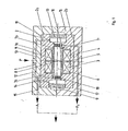
- the proposed solenoid valve consists of a housing 1, which is composed of the two parts la and lb, a yoke 2 consisting of two parts 2a, 2b, two coils 3 and 4, one coil relative to the other coil is wound in opposite directions, from a coil holder 5 holding the coils and seated in the yoke 2, from a swivel bearing 6 which can be pivoted about its center of gravity 8 in the central space 7 formed by the annular coils 3 and 4 and through the yoke 2 in the usual way is mounted, and from two permanent magnets 9 and 10, which lie opposite the ends of the armature 6 at an axial distance and bridge the yoke parts 2a, 2b.
- the central space 7 is expanded in the yoke regions adjoining the two anchor ends in order to fix the permanent magnets 9, 10 in the yoke 2.
- an annular one Membrane 11 is provided, by means of which the pivot armature 6 is pivotally mounted about its center of gravity 8 and which divides the central space into two closely spaced chambers 7a and 7b.
- the configuration and storage of the membrane 11, for example, is explained in more detail in connection with FIGS. 5 and 6.
- conduction paths for the fluid to be controlled are provided, which run according to FIG. 1 both in the housing 1 and in the yoke 2.
- the solenoid valve shown is a 2/2-way valve, in which the fluid signal arriving at the P connection reaches the chambers 7a and 7b via the line paths 12 and 13 shown in broken lines. Since the outlet openings 14 and 16 of the chambers 7a and 7b are open, the fluid can be passed on via the outlet line 15 as a working signal A1 and via the other outlet line 17 as a working signal A2.
- the openings 14 and 16 are opened and closed directly by the pivot armature 6, for which purpose it is provided with sealing layers 18, 19.
- the common P-connection shown can of course also be divided into two separate P-connections, so that two fluids can be controlled separately from one another with this solenoid valve.
- the corresponding working signals A1 and A2 are then available in the outlet lines 15 and 17. In this way there are two 2/2-way valves.
- the two outlet lines 15 and 17 can be combined, as is indicated by dash-dotted lines in FIG. 1. A cross-sectional summation of the outlet lines with a correspondingly strong working signal is thereby achieved.
- the function of the solenoid valve described is as follows.
- the initial position of the valve is the position of the armature 6 shown in FIG. 1.
- the coils 3 and 4 are energized to change the armature and thus to close the openings 14 and 16.
- Their opposite winding direction in conjunction with the opposite poles of the permanent magnets 9 and 10 according to FIG. 1, on the one hand weaken the magnetic forces of one permanent magnet and on the other hand strengthen the magnetic forces of the other permanent magnet, so that the armature is pivoted and closes the openings mentioned.
- the coils are then de-energized and the armature 6 is held in the new position by the force of the permanent magnets. No signals A1 and A2 are now available.
- the coils 3 and 4 are excited again, but now with reversed polarity, so that the armature 6 can pivot accordingly.
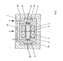
- Figure 2 shows a modified embodiment of the solenoid valve according to Figure 1.
- the change consists in that all fluid conduction paths are provided in the housing 1 and that a ring magnet 9.1 is assigned to each armature end, the ring magnets sitting on outer flanges of the coil carrier 5 and on the other hand by the Yoke parts 2a, 2b are surrounded.
- the yoke 2 and the housing 1 can thereby be made shorter than in the example according to FIG. 1.
- Figures 3 and 4 show further versions in the form of a 3/2-way valve and a 5/2-way valve.
- the structure of these valves differs from that of the solenoid valve according to FIGS. 1 and 2 only in the course of the fluid line paths.
- the function of these valves is also the same.
- FIG 3 leads from the P connection a feed line 20 to the chamber 7b, which in turn provides a working signal A via the opening 21 and the outlet line 22.
- the opening 21 is closed, so that the A connection communicates with the ventilation connection R, since the opening 23 of the other chamber 7a is open.
- Figure 4 shows the 5/2-way valve version. Fluid from the chambers 7a and 7b is supplied from the common P connection via the supply lines 24, 25.
- the opening 23 is open while the other opening 21 is closed, so that a work signal B is only available via the outlet line 26 of the chamber 7a.
- the chamber 7b is connected to the R connection via the ventilation line 27.
- the working signal A is available via the outlet line 28, and the ventilation line 29 to the ventilation outlet S is open.
- FIGS. 5 and 6 show details with regard to the shape and arrangement of the membrane 11, which is used to support the armature 6.
- the annular membrane 11 made of elastic material, e.g. Rubber, has the shape of a double T in cross section (FIG. 5), so that flanges 11a, 11b are present at its edges.
- the armature-side flange 11a is seated in a groove 6a of the armature 6, while the coil-side flange 11b is seated in a shoulder 5a of the coil carrier 5.
- a securing sleeve 30 pushed onto the shoulder prevents axial displacement of the membrane 11, the sleeve itself being axially secured by a latching configuration 31 of a known type.
- the flanges 11a, 11b can also be modified be replaced by beads.
- the use of a membrane for mounting the armature 6 has the advantage that the armature is supported in a practically friction-free manner, which results in a reduced electrical drive energy for the purpose of reversing the armature.
- the groove 6a of the armature 6 and the membrane flange 11a located in this groove are radial Anchor cross-section considered - e.g. elliptical, the major axis of the ellipse e.g. lies in the swivel plane of the armature (FIG. 6).
- a rectangular, square or similar design can also be provided.
- the generally circular flange 11b can e.g. have a straight part 11c which bears against a corresponding surface 5b of the step 5a.
- the material of the armature 6 and / or the yoke 2 consists of amorphous metal.
- This material can be remagnetized extremely quickly, so that particularly high switching frequencies of the armature can be achieved and a suitably equipped solenoid valve thus works very quickly.
- Amorphous metals are known and consist, for example, of alloys with 70 to 80 atom% of one or more magnetic materials, such as iron, cobalt and nickel, which can be provided with a small proportion of chromium or molybdenum for fine tuning. as well as the remainder from metalloids such as boron, silicon, carbon or phosphorus. Alloys of this type are formed into amorphous strips with a thickness of generally 50 micrometers, from which the corresponding components, in this case anchors and / or yokes, are then produced.
Landscapes
- Engineering & Computer Science (AREA)
- General Engineering & Computer Science (AREA)
- Physics & Mathematics (AREA)
- Electromagnetism (AREA)
- Mechanical Engineering (AREA)
- Magnetically Actuated Valves (AREA)
Applications Claiming Priority (2)
| Application Number | Priority Date | Filing Date | Title |
|---|---|---|---|
| DE3437487 | 1984-10-12 | ||
| DE3437487A DE3437487A1 (de) | 1984-10-12 | 1984-10-12 | Bistabiles magnetventil |
Publications (2)
| Publication Number | Publication Date |
|---|---|
| EP0177944A2 true EP0177944A2 (fr) | 1986-04-16 |
| EP0177944A3 EP0177944A3 (fr) | 1987-06-24 |
Family
ID=6247763
Family Applications (1)
| Application Number | Title | Priority Date | Filing Date |
|---|---|---|---|
| EP85112777A Withdrawn EP0177944A3 (fr) | 1984-10-12 | 1985-10-09 | Electrovanne bistable |
Country Status (4)
| Country | Link |
|---|---|
| US (1) | US4621660A (fr) |
| EP (1) | EP0177944A3 (fr) |
| JP (1) | JPS6196278A (fr) |
| DE (1) | DE3437487A1 (fr) |
Cited By (3)
| Publication number | Priority date | Publication date | Assignee | Title |
|---|---|---|---|---|
| FR2635367A1 (fr) * | 1988-08-12 | 1990-02-16 | Brasil Compressores Sa | Vanne de separation pour systemes de refrigeration ou de climatisation |
| EP0740752A1 (fr) * | 1994-01-19 | 1996-11-06 | Marotta Scientific Controls, Inc. | Soupape a verrouillage magnetique |
| CN107000729A (zh) * | 2014-10-20 | 2017-08-01 | 克诺尔商用车制动系统有限公司 | 用于车辆的制动器的倾翻式衔铁阀和用于运行倾翻式衔铁阀的方法 |
Families Citing this family (35)
| Publication number | Priority date | Publication date | Assignee | Title |
|---|---|---|---|---|
| DE3810154C2 (de) * | 1988-03-25 | 1994-03-03 | Kuhnke Gmbh Kg H | Elektromagnetventil mit Dauermagnethaltung |
| US4988074A (en) * | 1988-05-17 | 1991-01-29 | Hi-Ram, Inc. | Proportional variable force solenoid control valve |
| DE3834445A1 (de) * | 1988-10-10 | 1990-04-12 | Mesenich Gerhard | Elektromagnetisches einspritzventil mit kippanker |
| US4925112A (en) * | 1989-06-21 | 1990-05-15 | General Motors Corporation | Fuel injection |
| US5144982A (en) * | 1990-10-12 | 1992-09-08 | Milliken Research Corporation | Electro-pneumatic valve card assemblies |
| US5193781A (en) * | 1990-10-12 | 1993-03-16 | Milliken Research Corporation | Electro-pneumatic valve card assemblies |
| DE4110815C2 (de) * | 1991-04-04 | 1993-11-04 | Harting Elektronik Gmbh | Polarisierter umschlagmagnet |
| US5368274A (en) * | 1992-09-17 | 1994-11-29 | Wilson Greatbatch Ltd. | Low power electromagnetic valve |
| US5388614A (en) * | 1992-09-25 | 1995-02-14 | Nippon Soken, Inc. | Rotary flow control valve |
| DE4415068C2 (de) * | 1994-04-29 | 2002-11-07 | Festo Ag & Co | Bistabiles Magnetventil |
| TW479773U (en) * | 1996-12-01 | 2002-03-11 | Tadahiro Ohmi | Fluid control valve and fluid supply/exhaust system |
| GB2320311A (en) * | 1996-12-10 | 1998-06-17 | Appliance Components Ltd | Magnetically latched diverter valves |
| DE59811319D1 (de) * | 1997-06-09 | 2004-06-09 | Buerkert Werke Gmbh & Co | Miniaturisiertes magnetventil |
| DE29711175U1 (de) * | 1997-06-26 | 1998-07-23 | Siemens Ag | Magnetventil |
| NL1008703C1 (nl) * | 1998-01-08 | 1999-07-12 | Jan Hendrik Fondse | Meerwegklep. |
| AT407661B (de) * | 1998-08-04 | 2001-05-25 | Hygrama Ag | Druckmittelzylinder, weichenventil und druckmittelbetätigte arbeitseinheit |
| DE29822959U1 (de) * | 1998-12-23 | 1999-05-12 | Buerkert Werke Gmbh & Co | Steuerelement für Fluid |
| US6460558B2 (en) | 2000-12-04 | 2002-10-08 | Sauer-Danfoss, Inc. | Pilot stage or pressure control pilot valve having a single armature/flapper |
| US6467496B2 (en) | 2000-12-04 | 2002-10-22 | Sauer-Danfoss Inc. | Single-adjustment, dual-null pressure setting for an electrohydraulic valve pilot stage |
| GB2387968B (en) * | 2001-04-24 | 2004-06-23 | Camcon Ltd | Electromagnetically operated valve |
| GB0109975D0 (en) * | 2001-04-24 | 2001-06-13 | Camcon Ltd | Electromagnetically operated valve |
| EP1509716B1 (fr) * | 2002-05-31 | 2008-01-02 | Camcon Ltd. | Actionneur electromagnetique pivotant, actionneur integre et vanne de regulation d'ecoulement de fluide |
| WO2004104462A1 (fr) * | 2003-05-23 | 2004-12-02 | Camcon Ltd | Actionneur electromagnetique pivotant, actionneur integre et soupape de regulation de flux de fluide |
| US7252114B2 (en) * | 2003-05-30 | 2007-08-07 | Camcon Limited | Electromagnetic fluid flow control valve |
| US6791442B1 (en) | 2003-11-21 | 2004-09-14 | Trombetta, Llc | Magnetic latching solenoid |
| US7455075B2 (en) * | 2004-06-14 | 2008-11-25 | Minebea Co., Ltd. | Servo valve with miniature embedded force motor with stiffened armature |
| EP1851426B1 (fr) * | 2005-02-08 | 2009-11-25 | Robert Bosch GmbH | Fixation d'une armature a une pointeau de soupape dans une soupape de commande d'injecteur de carburant |
| JP2007046551A (ja) * | 2005-08-10 | 2007-02-22 | Alps Electric Co Ltd | 圧電ポンプ |
| WO2008028509A1 (fr) * | 2006-09-07 | 2008-03-13 | Fluid Automation Systems S.A. | Soupape bistable |
| US8579250B1 (en) * | 2010-06-16 | 2013-11-12 | Daniel Theobald | High precision energy efficient valve |
| US9368266B2 (en) | 2014-07-18 | 2016-06-14 | Trumpet Holdings, Inc. | Electric solenoid structure having elastomeric biasing member |
| US10024453B2 (en) * | 2016-07-15 | 2018-07-17 | Glen A. Robertson | Dual acting solenoid valve using bi-stable permanent magnet activation for energy efficiency and power versatility |
| EP3297004B1 (fr) * | 2016-09-15 | 2020-04-08 | Fas Medic S.A. | Actionneur electromagnetique a volet basculant |
| DE102017217791A1 (de) | 2017-10-06 | 2019-04-11 | Continental Teves Ag & Co. Ohg | Ventilanordnung und Bremssystem |
| CN108650573B (zh) * | 2018-05-10 | 2020-06-02 | 东莞宜安科技股份有限公司 | 动铁耳机 |
Citations (13)
| Publication number | Priority date | Publication date | Assignee | Title |
|---|---|---|---|---|
| US2915077A (en) * | 1957-01-30 | 1959-12-01 | Robertshaw Fulton Controls Co | Diaphragm-flapper assembly |
| US2936783A (en) * | 1957-03-11 | 1960-05-17 | Sperry Rand Corp | Electro-hydraulic servo control valve |
| DE1195116B (de) * | 1959-08-31 | 1965-06-16 | Borg Warner | Steuereinrichtung fuer einen doppeltwirkenden Verbraucher mit einem Kolbenschieber |
| DE1268921B (de) * | 1965-12-30 | 1968-05-22 | Zd Y Pruumyslove Automatizace | Steuerglied der Duesensteuerung bei hydraulischen Regelschiebern |
| GB1117794A (en) * | 1965-08-16 | 1968-06-26 | Fisher Governor Co | Electro-pneumatic transducer |
| US3532121A (en) * | 1969-01-15 | 1970-10-06 | Bell Aerospace Corp | Latching valve |
| DE2022830A1 (de) * | 1969-05-12 | 1970-11-19 | Borg Warner | Elektro-hydraulisches Servoventil |
| DE1589086A1 (de) * | 1966-12-06 | 1972-03-23 | Z Prumyslove Automatisace | Verfahren fuer die Betaetigung des Ankers elektrohydraulischer Umsetzer fuer hydraulische Verstaerker |
| DE2511152A1 (de) * | 1975-03-14 | 1976-09-23 | Daimler Benz Ag | Elektromagnetisches steuerventil, insbesondere fuer selbsttaetig schaltende kraftfahrzeug-getriebe |
| DE7615072U1 (de) * | 1976-05-12 | 1977-03-31 | Buerkert Gmbh, 7118 Ingelfingen | Direktwirkendes 2/2-, 3/2-wege-magnetventil |
| DE2826212A1 (de) * | 1977-06-18 | 1979-03-22 | Hart J C H | Betaetigungsvorrichtung |
| DE2032361C3 (de) * | 1969-07-01 | 1981-01-15 | Moog Inc., East Aurora, N.Y. (V.St.A.) | Zweistufiges Servosteuerventil |
| DE2900473C2 (de) * | 1979-01-08 | 1982-12-30 | Deutsche Forschungs- und Versuchsanstalt für Luft- und Raumfahrt e.V., 5000 Köln | Magnetisch betätigtes bistabiles 3/2-Wegeventil |
Family Cites Families (5)
| Publication number | Priority date | Publication date | Assignee | Title |
|---|---|---|---|---|
| US3026892A (en) * | 1957-06-26 | 1962-03-27 | Pneumo Dynamics Corp | Electrohydraulic servo valve |
| US3215162A (en) * | 1962-04-20 | 1965-11-02 | Ford Motor Co | Bistable control valve |
| FR1364650A (fr) * | 1963-05-02 | 1964-06-26 | Ct De Rech S Hydrauliques Et E | Servo-commande électro-hydraulique, à contre-réaction pour commandes de force |
| GB1138305A (en) * | 1966-05-07 | 1969-01-01 | Bullfinch Gas Equip | Improvements in a fluid flow control valve |
| US3457955A (en) * | 1967-01-03 | 1969-07-29 | Garrett Corp | Aerodynamically balanced valve |
-
1984
- 1984-10-12 DE DE3437487A patent/DE3437487A1/de active Granted
-
1985
- 1985-10-09 EP EP85112777A patent/EP0177944A3/fr not_active Withdrawn
- 1985-10-11 JP JP60224990A patent/JPS6196278A/ja active Pending
- 1985-10-11 US US06/786,812 patent/US4621660A/en not_active Expired - Fee Related
Patent Citations (13)
| Publication number | Priority date | Publication date | Assignee | Title |
|---|---|---|---|---|
| US2915077A (en) * | 1957-01-30 | 1959-12-01 | Robertshaw Fulton Controls Co | Diaphragm-flapper assembly |
| US2936783A (en) * | 1957-03-11 | 1960-05-17 | Sperry Rand Corp | Electro-hydraulic servo control valve |
| DE1195116B (de) * | 1959-08-31 | 1965-06-16 | Borg Warner | Steuereinrichtung fuer einen doppeltwirkenden Verbraucher mit einem Kolbenschieber |
| GB1117794A (en) * | 1965-08-16 | 1968-06-26 | Fisher Governor Co | Electro-pneumatic transducer |
| DE1268921B (de) * | 1965-12-30 | 1968-05-22 | Zd Y Pruumyslove Automatizace | Steuerglied der Duesensteuerung bei hydraulischen Regelschiebern |
| DE1589086A1 (de) * | 1966-12-06 | 1972-03-23 | Z Prumyslove Automatisace | Verfahren fuer die Betaetigung des Ankers elektrohydraulischer Umsetzer fuer hydraulische Verstaerker |
| US3532121A (en) * | 1969-01-15 | 1970-10-06 | Bell Aerospace Corp | Latching valve |
| DE2022830A1 (de) * | 1969-05-12 | 1970-11-19 | Borg Warner | Elektro-hydraulisches Servoventil |
| DE2032361C3 (de) * | 1969-07-01 | 1981-01-15 | Moog Inc., East Aurora, N.Y. (V.St.A.) | Zweistufiges Servosteuerventil |
| DE2511152A1 (de) * | 1975-03-14 | 1976-09-23 | Daimler Benz Ag | Elektromagnetisches steuerventil, insbesondere fuer selbsttaetig schaltende kraftfahrzeug-getriebe |
| DE7615072U1 (de) * | 1976-05-12 | 1977-03-31 | Buerkert Gmbh, 7118 Ingelfingen | Direktwirkendes 2/2-, 3/2-wege-magnetventil |
| DE2826212A1 (de) * | 1977-06-18 | 1979-03-22 | Hart J C H | Betaetigungsvorrichtung |
| DE2900473C2 (de) * | 1979-01-08 | 1982-12-30 | Deutsche Forschungs- und Versuchsanstalt für Luft- und Raumfahrt e.V., 5000 Köln | Magnetisch betätigtes bistabiles 3/2-Wegeventil |
Cited By (5)
| Publication number | Priority date | Publication date | Assignee | Title |
|---|---|---|---|---|
| FR2635367A1 (fr) * | 1988-08-12 | 1990-02-16 | Brasil Compressores Sa | Vanne de separation pour systemes de refrigeration ou de climatisation |
| EP0740752A1 (fr) * | 1994-01-19 | 1996-11-06 | Marotta Scientific Controls, Inc. | Soupape a verrouillage magnetique |
| EP0740752A4 (fr) * | 1994-01-19 | 1998-07-22 | Marotta Scientific Controls | Soupape a verrouillage magnetique |
| CN107000729A (zh) * | 2014-10-20 | 2017-08-01 | 克诺尔商用车制动系统有限公司 | 用于车辆的制动器的倾翻式衔铁阀和用于运行倾翻式衔铁阀的方法 |
| CN107000729B (zh) * | 2014-10-20 | 2019-07-19 | 克诺尔商用车制动系统有限公司 | 用于车辆的制动器的倾翻式衔铁阀和用于运行倾翻式衔铁阀的方法 |
Also Published As
| Publication number | Publication date |
|---|---|
| JPS6196278A (ja) | 1986-05-14 |
| DE3437487C2 (fr) | 1988-08-25 |
| US4621660A (en) | 1986-11-11 |
| DE3437487A1 (de) | 1986-04-17 |
| EP0177944A3 (fr) | 1987-06-24 |
Similar Documents
| Publication | Publication Date | Title |
|---|---|---|
| EP0177944A2 (fr) | Electrovanne bistable | |
| EP0469385B1 (fr) | Système magnétique | |
| EP0203453B1 (fr) | Electrovanne | |
| DE2636985C3 (de) | Tauchankermagnet, sowie dessen Verwendung in einem Drahtmatrixdrucker | |
| EP3356711B1 (fr) | Dispositif d'entraînement électromagnétique pour effectuer un déplacement linéaire | |
| DE2110596B2 (de) | Magnetventil | |
| DE3730381C2 (de) | Bistabiles Magnetventil mit dauermagnetischer Haltekraft | |
| EP2240943A2 (fr) | Aimant de commande | |
| DE3528296A1 (de) | Magnetventil | |
| DE2229332C3 (de) | Wandler | |
| EP0564794A1 (fr) | Electro-aimant de commande à double effet | |
| EP0204181A1 (fr) | Electroaimant | |
| DE2856113A1 (de) | Elektromagnetventil | |
| DE4415068C2 (de) | Bistabiles Magnetventil | |
| DE3804011C1 (en) | Solenoid valve arrangement | |
| WO1999025595A1 (fr) | Electrovanne | |
| DE3543473C2 (fr) | ||
| DE19607933A1 (de) | Elektromagnetventil | |
| DE4000071A1 (de) | Magnetventil | |
| DE2407136A1 (de) | Wegeventil mit raste zur festlegung der schaltstellungen des steuerkolbens | |
| DE2349155A1 (de) | Stopfbuchsenloses magnetventil fuer aggressive medien | |
| DE3609901A1 (de) | Elektromagnetisch betaetigtes, hydraulisches schnellschaltventil | |
| DE3132896A1 (de) | Elektromagnetrischer antrieb, beispielsweise fuer ein ventil, eine foerderpumpe oder dergleichen | |
| DE679714C (de) | Elektromagnetisch gesteuertes Saugventil fuer Ammoniakdampfverdichter | |
| DE3537435A1 (de) | 3/2-wege-magnetventil |
Legal Events
| Date | Code | Title | Description |
|---|---|---|---|
| PUAI | Public reference made under article 153(3) epc to a published international application that has entered the european phase |
Free format text: ORIGINAL CODE: 0009012 |
|
| AK | Designated contracting states |
Kind code of ref document: A2 Designated state(s): AT CH FR GB IT LI NL SE |
|
| PUAL | Search report despatched |
Free format text: ORIGINAL CODE: 0009013 |
|
| AK | Designated contracting states |
Kind code of ref document: A3 Designated state(s): AT CH FR GB IT LI NL SE |
|
| 17P | Request for examination filed |
Effective date: 19871218 |
|
| 17Q | First examination report despatched |
Effective date: 19881208 |
|
| STAA | Information on the status of an ep patent application or granted ep patent |
Free format text: STATUS: THE APPLICATION IS DEEMED TO BE WITHDRAWN |
|
| 18D | Application deemed to be withdrawn |
Effective date: 19890517 |
|
| RIN1 | Information on inventor provided before grant (corrected) |
Inventor name: KLOCKE, HARALD |