EP0177084A2 - Umrissbearbeitungsmaschine - Google Patents
Umrissbearbeitungsmaschine Download PDFInfo
- Publication number
- EP0177084A2 EP0177084A2 EP85201476A EP85201476A EP0177084A2 EP 0177084 A2 EP0177084 A2 EP 0177084A2 EP 85201476 A EP85201476 A EP 85201476A EP 85201476 A EP85201476 A EP 85201476A EP 0177084 A2 EP0177084 A2 EP 0177084A2
- Authority
- EP
- European Patent Office
- Prior art keywords
- working
- work
- working tool
- tool
- computing unit
- Prior art date
- Legal status (The legal status is an assumption and is not a legal conclusion. Google has not performed a legal analysis and makes no representation as to the accuracy of the status listed.)
- Granted
Links
Images


Classifications
-
- G—PHYSICS
- G05—CONTROLLING; REGULATING
- G05B—CONTROL OR REGULATING SYSTEMS IN GENERAL; FUNCTIONAL ELEMENTS OF SUCH SYSTEMS; MONITORING OR TESTING ARRANGEMENTS FOR SUCH SYSTEMS OR ELEMENTS
- G05B19/00—Programme-control systems
- G05B19/02—Programme-control systems electric
- G05B19/18—Numerical control [NC], i.e. automatically operating machines, in particular machine tools, e.g. in a manufacturing environment, so as to execute positioning, movement or co-ordinated operations by means of programme data in numerical form
- G05B19/41—Numerical control [NC], i.e. automatically operating machines, in particular machine tools, e.g. in a manufacturing environment, so as to execute positioning, movement or co-ordinated operations by means of programme data in numerical form characterised by interpolation, e.g. the computation of intermediate points between programmed end points to define the path to be followed and the rate of travel along that path
-
- G—PHYSICS
- G05—CONTROLLING; REGULATING
- G05B—CONTROL OR REGULATING SYSTEMS IN GENERAL; FUNCTIONAL ELEMENTS OF SUCH SYSTEMS; MONITORING OR TESTING ARRANGEMENTS FOR SUCH SYSTEMS OR ELEMENTS
- G05B19/00—Programme-control systems
- G05B19/02—Programme-control systems electric
- G05B19/18—Numerical control [NC], i.e. automatically operating machines, in particular machine tools, e.g. in a manufacturing environment, so as to execute positioning, movement or co-ordinated operations by means of programme data in numerical form
- G05B19/182—Numerical control [NC], i.e. automatically operating machines, in particular machine tools, e.g. in a manufacturing environment, so as to execute positioning, movement or co-ordinated operations by means of programme data in numerical form characterised by the machine tool function, e.g. thread cutting, cam making, tool direction control
-
- G—PHYSICS
- G05—CONTROLLING; REGULATING
- G05B—CONTROL OR REGULATING SYSTEMS IN GENERAL; FUNCTIONAL ELEMENTS OF SUCH SYSTEMS; MONITORING OR TESTING ARRANGEMENTS FOR SUCH SYSTEMS OR ELEMENTS
- G05B2219/00—Program-control systems
- G05B2219/30—Nc systems
- G05B2219/49—Nc machine tool, till multiple
- G05B2219/49362—Tool, probe at constant height to surface during machining
-
- G—PHYSICS
- G05—CONTROLLING; REGULATING
- G05B—CONTROL OR REGULATING SYSTEMS IN GENERAL; FUNCTIONAL ELEMENTS OF SUCH SYSTEMS; MONITORING OR TESTING ARRANGEMENTS FOR SUCH SYSTEMS OR ELEMENTS
- G05B2219/00—Program-control systems
- G05B2219/30—Nc systems
- G05B2219/50—Machine tool, machine tool null till machine tool work handling
- G05B2219/50072—Machine workpiece again to correct previous errors
-
- G—PHYSICS
- G05—CONTROLLING; REGULATING
- G05B—CONTROL OR REGULATING SYSTEMS IN GENERAL; FUNCTIONAL ELEMENTS OF SUCH SYSTEMS; MONITORING OR TESTING ARRANGEMENTS FOR SUCH SYSTEMS OR ELEMENTS
- G05B2219/00—Program-control systems
- G05B2219/30—Nc systems
- G05B2219/50—Machine tool, machine tool null till machine tool work handling
- G05B2219/50353—Tool, probe inclination, orientation to surface, posture, attitude
-
- Y—GENERAL TAGGING OF NEW TECHNOLOGICAL DEVELOPMENTS; GENERAL TAGGING OF CROSS-SECTIONAL TECHNOLOGIES SPANNING OVER SEVERAL SECTIONS OF THE IPC; TECHNICAL SUBJECTS COVERED BY FORMER USPC CROSS-REFERENCE ART COLLECTIONS [XRACs] AND DIGESTS
- Y10—TECHNICAL SUBJECTS COVERED BY FORMER USPC
- Y10T—TECHNICAL SUBJECTS COVERED BY FORMER US CLASSIFICATION
- Y10T408/00—Cutting by use of rotating axially moving tool
- Y10T408/16—Cutting by use of rotating axially moving tool with control means energized in response to activator stimulated by condition sensor
- Y10T408/17—Cutting by use of rotating axially moving tool with control means energized in response to activator stimulated by condition sensor to control infeed
- Y10T408/172—Responsive to Tool
-
- Y—GENERAL TAGGING OF NEW TECHNOLOGICAL DEVELOPMENTS; GENERAL TAGGING OF CROSS-SECTIONAL TECHNOLOGIES SPANNING OVER SEVERAL SECTIONS OF THE IPC; TECHNICAL SUBJECTS COVERED BY FORMER USPC CROSS-REFERENCE ART COLLECTIONS [XRACs] AND DIGESTS
- Y10—TECHNICAL SUBJECTS COVERED BY FORMER USPC
- Y10T—TECHNICAL SUBJECTS COVERED BY FORMER US CLASSIFICATION
- Y10T409/00—Gear cutting, milling, or planing
- Y10T409/30—Milling
- Y10T409/304536—Milling including means to infeed work to cutter
- Y10T409/304648—Milling including means to infeed work to cutter with control means energized in response to activator stimulated by condition sensor
- Y10T409/30476—In response to work or work carriage
- Y10T409/304872—In response to work or work carriage to control limit of infeed
- Y10T409/304984—Adapted to electrically stimulate control
-
- Y—GENERAL TAGGING OF NEW TECHNOLOGICAL DEVELOPMENTS; GENERAL TAGGING OF CROSS-SECTIONAL TECHNOLOGIES SPANNING OVER SEVERAL SECTIONS OF THE IPC; TECHNICAL SUBJECTS COVERED BY FORMER USPC CROSS-REFERENCE ART COLLECTIONS [XRACs] AND DIGESTS
- Y10—TECHNICAL SUBJECTS COVERED BY FORMER USPC
- Y10T—TECHNICAL SUBJECTS COVERED BY FORMER US CLASSIFICATION
- Y10T409/00—Gear cutting, milling, or planing
- Y10T409/30—Milling
- Y10T409/306664—Milling including means to infeed rotary cutter toward work
- Y10T409/306776—Axially
- Y10T409/306832—Axially with infeed control means energized in response to activator stimulated by condition sensor
- Y10T409/306888—In response to cutter condition
-
- Y—GENERAL TAGGING OF NEW TECHNOLOGICAL DEVELOPMENTS; GENERAL TAGGING OF CROSS-SECTIONAL TECHNOLOGIES SPANNING OVER SEVERAL SECTIONS OF THE IPC; TECHNICAL SUBJECTS COVERED BY FORMER USPC CROSS-REFERENCE ART COLLECTIONS [XRACs] AND DIGESTS
- Y10—TECHNICAL SUBJECTS COVERED BY FORMER USPC
- Y10T—TECHNICAL SUBJECTS COVERED BY FORMER US CLASSIFICATION
- Y10T409/00—Gear cutting, milling, or planing
- Y10T409/30—Milling
- Y10T409/306664—Milling including means to infeed rotary cutter toward work
- Y10T409/307224—Milling including means to infeed rotary cutter toward work with infeed control means energized in response to activator stimulated by condition sensor
- Y10T409/30728—In response to cutter condition
Definitions
- This invention relates to a profile working machine such as die-finishing cutting machine, ceramics-working cutting machine, three-dimensional milling machine or the like.
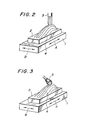
- FIG. 2 is a perspective view illustrating cutting work by a ball end mill.
- a table 1 of a working machine a work 2 fixedly held on the table 1, and a ball end mill 3 for cutting the work 2.
- Machining of the work by such a working machine is performed in the following manner. Namely, the work is cut by shifting the table 1 in a direction indicated by the arrow A while moving the ball end mill 3 up and down. Upon completion of the cutting in the direction A, the table 1 is shifted a little bit in a direction indicated by the arrow B (pick-feed) and cutting is again performed in the direction A. These operations are repeated successively. In this case, cutting tool marks 4 are caused to remain due to the pick-feed on the surface of the work.
- the work machined in such a way cannot be used as a final product. It is therefore necessary to add a further step to remove the cutting tool marks 4 in order to convert the above-machined work into a final product.
- the above-described cutting tool marks 4 are left with a substantially equal interval on the surface of the work and their heights range approximately from 0.1 mm to 0.2 mm. It should be noted that the cutting tool marks 4 shown in Figures 2 and 3 are exaggerated to facilitate their understanding. The heights of these cutting tool marks 4 must be reduced to at least 1 ⁇ m to 0.5 ⁇ m.
- FIG. 3 is a perspective view showing conventional grinding work, in which like elements of structure to those shown in Figure 2 will be designated by like reference numerals.
- Numeral 5 indicates a shafted grinder which is attached to a working machine.
- the profile of the work is in advance stored in a computer or the like and on the basis of the thus- stored information, cutting tool marks 4 are traced by the shafted grinder.
- the heights of the cutting tool marks 4 are as low as several tenths millimeter or so as mentioned above and their sizes and shapes are irregular.
- the working tool may cut the work too deep at certain parts and may be detached from the work at some other parts.
- Figures 4(a), 4(b) and 4(c) are respectively a front view, plan view and side view of a working tool and work. It is necessary to control the relative positional relationship between the working tool and work in order to press the working tool at a constant pressing force against the work as mentioned above. For this purpose, it is necessary to preset coordinate axes. Figures 4(a) through 4(c) show such coordinate axes. In the figures, there are shown a table 1, work 2 and working tool 6. The working tool 6 has a center O of rotation, and it has a profile which contains a spherical surface having a radius r.
- Numeral 7a indicates an arm for rotating the working tool 6
- numeral 7b is a support arm
- numeral 8 designates a load sensor connected rigidly to the support arm 7b
- numeral 9 is a drive source for rotating the arm 7a.
- the drive source 9 is attached rigidly to one end of the load sensor 8, which one end is opposite to the end to which the support arm 7a is rigidly connected.
- a variety of load sensors have been known for the load sensor 8. It is however desirable to use a load sensor of such a type as proposed in Japanese Patent Laid-Open No. 62497/1985 (which corresponds to European Patent Application No. 84200591.0 of April 26, 1984).
- the arm 7b is coupled to an unillustrated main body of a working machine and is rotated and displaced three-dimensionally.
- a coordinate system X-Y-Z has been established with a suitable portion Om of the main body of the working machine being as an origin, while a coordinate system x-y-z is established with the center 0 of rotation of the working tool 6 being as its origin.
- Letter T indicates a point of action (working point) of the working tool 6 on the work 2
- letter F indicates a working reaction force exerted on the working tool 6.
- the table 1 is, in most general forms, turnable about any of three axes which are not contained in the same plane. This function of the table is however omitted in the figures.
- FIG. 5 is an enlarged front view of the working tool 6 and work 2.
- the work 2 working tool 6, working point T, working reaction force F and flat surface P tl on the work 2.
- ⁇ - ⁇ which includes the working point T as its origin, as shown in the figure.
- the ⁇ -axis is placed as a line.passing through the working point T and the center 0 of the working tool 6, while the ⁇ -axis is defined as an intersecting line between the plane P tl , which is perpendicular to the ⁇ -axis, and a plane defined by the feeding direction (the direction of the x-axis) of the working tool 6 and the ⁇ -axis. Since the coordinate system has been established in the above-mentioned manner, the ⁇ -axis is coincided with the z-axis and the ⁇ -axis extends in parallel with the x-axis.
- the magnitude F and direction ⁇ of the working reaction force F change in various ways. Conditions under which the grinding efficiency and the quality of finishing are optimized may be achieved by controlling the magnitude F and direction v of the working reaction force F to their respective optimum values F 0 , ⁇ 0 . In view of this, a control system shown in Figure 6 may be contemplated.
- FIG 6 is a system diagram of a working machine, in which the working machine is applied to a flat work surface.
- a working tool/work system 10 composed of the working tool 6, table 1, work 2 and the like, a load sensor 8 shown in Figures 4(a) and 4(b), and drive and control systems 11 for individual axes.
- the drive and control systems 11 for the respective axes are composed of drive and control systems, which are adapted to control the drive of the working tool 6 in the directions of respective axes on the basis of the X-Y-Z coordinate system, and other drive and control systems for controlling the tiltings ( ⁇ 1' ⁇ 2 , ⁇ 3 ) about the three axes so as to control the relative positions of the working tool 6 and work 2.
- the drive and control systems 11 drive and control the working tool 6 and/or table 1 so as to establish desired relative positions between the working tool 6 and work 2.
- Designated at numeral 12 means a controlling and computing unit for performing prescribed operations in accordance with each detection signal from the load sensor 8.
- components F which is equal to the force component F ⁇ in this case
- F which is equal to the force component F ⁇
- the controlling and computing unit 12 computes, based on the detection signals, such desirable values X,Y of the relative positions X,Y between the working tool 6 and the work 2 that the magnitude F and direction ⁇ should become their respective optimum values F O and ⁇ 0 .
- the values X,Z computed at the controlling and computing unit 12 are then input to the drive and control systems 11 for respective axes.
- the drive and control systems 11 for respective axes change the relative positions in the working tool/work system 10 to new relative positions X,Z.
- the magnitude F and direction ⁇ of the reaction force are maintained respectively at their optimum values F O and ⁇ 0 .
- the working tool 6 is pressed under the constant pressing force against the work 2, whereby to permitting automatic machining without developing breakage or abrupt wearing on the working tool 6 while maintaining the optimum working conditions.
- the operation at the controlling and computing unit 12 will be described in further detail. It is dependent on the material of the work 2 and the material, shape, rotation speed, rotating direction, etc. of the working tool 6 how the working reaction force changes in accordance with a varied depth of cut and a feeding speed. Namely, the working reaction force is not constant. Therefore, it is not possible to show the computing means of the controlling and computing unit 12 in a general form. According to findings obtained through experiments, the direction ⁇ of the working reaction force remains substantially at a constant value ⁇ 0 in the neighbourhood of practical feeding speeds and depths of cut.
- the working reaction force can be controlled if either one of the values F and F ⁇ , which are components of the working reaction force, is detected and the thus-detected value F ⁇ or F ⁇ is controlled to the ⁇ -axis force component F ⁇ 0 or ⁇ -axis force component F ⁇ 0 of the above-described optimum value F O .
- the control algorithm of the controlling and computing unit 12 will hereinafter be described.
- the controlling and computing unit 12 may be adapted to perform an operation in such a way that by paying attention for example only to the normal force component F ⁇ , a value capable of controlling the relative positions of the working tool 6 and work 2 in the direction of the -axis (which is equal to the direction of the z-axis in this case) so as to make the force component F ⁇ approach the optimum value F ⁇ 0 is calculated.
- the speed v ⁇ may for example be chosen to A 1 (F ⁇ - F ⁇ 0 ), in which A is a positive constant, and the optimum value F ⁇ 0 is represented by F O cos ⁇ 0 .
- the speed v ⁇ in the direction of the ⁇ -axis which is equivalent to the feeding direction, is always kept at a constant feeding speed v t
- the velocities v x ,v z in the direction of the x-axis and z-axis are respectively represented as follows:
- the angle can be represented as follow: Since the x-axis and z-axis are respectively parallel to the coordinate axes X and Z of the main body of the working machine, the values X and Z may be calculated on the basis of the outputs from the controlling and computing unit 12 in the above case while supposing
- the above-described control algorithm of the controlling and computing unit 12 is to perform continuous control in the direction of the -axis in accordance with the difference ⁇ F ⁇ between the force component F c and the optimum value F ⁇ 0 .
- the following means may however be employed in order to further simplify the operation and control in the controlling and computing unit 12. Such means will next be described with reference to a block diagram depicted in Figure 7.
- Figure 7 is an enlarged front view of the working tool 6 and work 2, for describing the operation of the controlling and computing unit.
- forces, angle, points, axes, etc. similar to those shown in Figure 5 are identified by like reference letters.
- D 1 - D 5 are vectors indicating the magnitudes and directions of speeds preset with the point O being a center.
- the degrees of difference between the detected force component F and its optimum value F ⁇ 0 are classified into five ranges, and the velocity in each range with which the working tool 6 should move to let F ⁇ coincide with F ⁇ 0 is made correspond to each one of the said five vectors D 1 - D 5 , and thus an x-axis component v x and a z-axis component v z which the controlling and computing unit 12 should output are gained from the vector.
- Velocity components to be obtained when the five ranges are rendered corresponding to the vectors respectively may be summarized as shown in Table 1.
- the value v 0 is a constant value which is chosen from working specification and is close to the ideal feeding speed v f .
- the angle ⁇ is limited discretely to five directions unlike the said means for performing continuous control in the direction of the ⁇ -axis.
- the speeds v x ,vy are limited in advance to the three values 0, v 0 and -v 0 . Therefore, it may be expected that the control may somewhat lack smoothness.
- the cycle time of operations is a very small value. Accordingly, no inconvenience or problem will practically arise even when control is performed by such means.
- the outputs v x ,v Z may each require only three levels which correspond to the values 0, v 0 and -v o .
- the computing system can be simplified to a significant extent.
- the constants which are employed in Table 1 to classify the values F ⁇ are not necessarily limited to the values given in Table 1 but may stand for a variety of suitable values.
- An object of this invention is therefore to provide a profile working machine which can automatically machine a work having a curved surface, the profile of which is not exactly known, without developing breakage or abrupt wearing on a working tool.
- the present invention provides a profile working machine equipped with a support for holding a work in place, a working tool for machining the work and drive and control systems for controlling the relative displacements between the support and working tool and adapted to machine the work into a desired profile, which machine comprises:
- the present invention performs working or machining by tracing the shape of a curved-surface of each work while maintaining the working reaction force, which is exerted to the working tool, at optimum magnitude and direction. It is thus possible to automatically work or machine a work, the exact shape of which is unknown, under ideal working conditions without developing breakage or abrupt wearing on the working tool. Therefore, the working is rendered easy, leading to man power saving of the working and uniform accuracy of working finish. As a result of the working, data on the shape of the work can be collected, whereby making it possible to proceed efficiently with subsequent steps.
- FIG. 1 is a system diagram of a profile working machine according to one embodiment of this invention.
- units of system similar to those illustrated in Figure 6 are indicated by like reference numerals.
- Numeral 8' indicates a load sensor for detecting force components along respective axes and moment components about respective axes.
- Designated at numeral 15 is a controlling and computing unit the structure of which is different from the controlling and computing unit 12 illustrated in Figure 6.
- the controlling and computing unit 15 is composed of a memory 15A for storing data on the shape of a working tool, a system 15B for calculating a working point and tangential plane (which may hereinafter be called “working point/tangential plane calculation system 15B), and a controlling and computing unit 15C for the working point and working reaction force (which may hereinafter be called “working point/working reaction force controlling and computing unit 15C").
- Numeral 16 indicates displacement sensors for detecting displacements of the working tool 6 and the table 1. In the machine of this embodiment, the same coordinate systems X-Y-Z and x-y-z as those shown in Figures 4(a) through 4(c) are employed.
- the load sensor 8 detects the working reaction force F and a moment M (M x ,M y ,M z ) produced by the force components of the working reaction force.
- the working point/tangential plane calculation system 15B is input with the force F and moment M detected by the load sensor 8' as well as the relative positions X,Y,Z (hereinafter represented generally by "X") and relative angles of spatial orientation ⁇ 1 , ⁇ 2 , ⁇ 3 (hereinafter represented generally by”h)") of the working tool 6 and table 1, which relative positions and angles have been detected by the displacement sensors 16, and dimensional data S of the working tool 6 indicated by the memory 15A for storing data on the shape of the working tool. Based on the thus-input information, the working point/tangential plane calculation system 15B determines the coordinate values of the working point T and the tangential plane P t which passes through the working point T and is in contact with the working tool 6.
- the working point/working reaction force controlling and computing unit 15C is fed with the working point T and tangential plane P t determined by the working point/tangential plane calculation system 15B, the force F detected by the load sensor 8' and the outputs X,e) of the displacement sensor 16. Based on the thus-input values, the working point/working reaction force controlling and computing unit 15C computes the relative positions and relative angles of spatial orientation required respectively for the working tool 6 and work 2, and then outputs them as command values X ⁇ ,H ⁇ ) to the drive and control systems 11 for the respective axes.
- the drive and control systems 11 for the respective axes drive and control the working tool 6 and work 2 on the basis of the command values X ⁇ ,H ⁇ ) so that the working tool 6 and work 2 satisfy the above-mentioned desired relative positions and relative angles of spatial orientation.
- the above-mentioned relative positions and relative angles of spatial orientation which are computed at the working point/working reaction force controlling and computing unit 15C, are relative positions and relative angles of spatial orientation which are both required to hold the working point T within the machinable range of the working tool 6 or desirably within a range permitting best working conditions and also to maintain the magnitude and direction of the working reaction force F within the ranges of values (optimum values) capable of satisfying optimum working conditions.
- the working tool 6 is pressed at a constant pressing force against the work 2 even when the work 2 has a three-dimentionally curved surface, to say nothing of a horizontal surface.
- automatic machining can be performed without developing breakage or abrupt wearing on the working tool 6 while maintaining the optimum working conditions.
- Figure 8 is the system diagram of a profile working machine applied to such a surface.
- Figure 9 is an enlarged front view of the working tool 6 and work 2 in the above case.
- similar units of system to those shown in Figure 1 are indicated by like reference numerals.
- the displacement sensor 16 is omitted and the values input to and output from respective units are specifically given.
- Figure 9 illustrates a state in which the working tool 6 having a circular cross-section with the radius of r is machining a tilted surface of the work 2.
- Letter a indicates the angle of tilting of the tilted surface to the horizontal plane.
- FIG. 10(a), 10(b) and 10(c) are respectively an enlarged front view, enlarged plan view and enlarged side view of a working tool and work.
- the working point T (x t ,y t ,z t ) is not on any of the axes and changes three-dimensionally.
- Letter y 0 indicates the distance between the center O of the working tool 6 and the reference point Q of the load sensor 8'.
- Equations (5) to (7) represent relationship which can always be established between the force components F x ,F y ,F z and the moment components M x ,M y ,M z
- Equation (8) represents that the working point T is located on the surface (a spherical surface having a radius r) of the working tool 6. From Equations (6) and (7), the following equations can be derived.
- Equation 11 Introducing Equations (9) and (10) into Equation (8) and solving Equation (8) with respect to x t ,
- Equation 11 supposing the solution of Equation 11 is
- Equation (5),(7) will become unnecessary because they are simplified respectively to the following obvious equations:
- the working point/tangential plane calculation system 15B receives the force components F x , Fz and the moment component M from the load sensor 8' and the radius r of the working tool 6 from the working tool shape data memory 15A, performs an operation in accordance with Equation (20), and then outputs the angle a of tilting of the tangential plane P t to the working point/working reaction force controlling and computing unit 15C.
- ⁇ (the direction relative to the -axis) in which the working tool 6 should be advanced and the speeds v x ,v z at which the working tool 6 should be advanced respectively in the directions of the x-axis and z-axis.
- ⁇ is deemed to be equivalent to ⁇ 0 ( ⁇ ⁇ ⁇ 0 ).
- FIG. 11(a) is an enlarged front view of the working tool and work under the former situation
- Figure 11(b) is an enlarged side view of the same working tool and work under the latter situation.
- letter v indicates the magnitude of the speed at which the working tool 6 should be advanced.
- FIG. 15C is an enlarged front elevation of the working tool and work.
- an angle ( ⁇ + ⁇ ) obtained by adding the input angle a to the angle calculated in accordance with Equation (27) or Equation (30) is classified into 9 ranges.
- the x-axis component v x and z-axis component v z of each of the vectors are obtained.
- Values to be obtained when the nine ranges are rendered corresponding to the vectors respectively in the above manner are given in Table 2.
- the working reaction force F (F x ,F y ,F z ) and the moment M (M x ,M y ,M z ) produced on the basis of the reaction force, which reaction force and moment have been detected by the load sensor 8', as well as data S on the shape of the working tool are input to the working point/tangential plane calculation system 15B, whereby to determine the coordinate values (x t ,x y ,x z ) of the contact point T (working point) between the working tool 6 and work 2.
- the above-described Equation (5) to Equation (7) are established between the respective force components F x ,F y ,F z and moment components M x ,My,M z and the coordinate values of the working point T.
- Equation (8) is also satisfied as the working point T is located on the surface of the working tool 6. Accordingly, the coordinate values (x t ,y t ,z t ) of the working point T can be determined from Equation (5) to Equation (8) as expressed in Equation (13), Equation (14) and Equation (15).
- the tangential plane P t can also be determined as a plane which extends through the working point T and is perpendicular to the line O-T. The above calculations are feasible when the axes of the X-Y-Z coordinate system are respectively kept in parallel with their corresponding axes of the x-y-z coordinate system.
- a cylindrical coordinate system (a coordinate system employed where the relative positions of the working tool 6 and work 2 change in a cylindrical form) is used by way of example, the coordinates of the wording point T and tangential plane P t cannot be determined unless the values X,@) detected by the displacement sensors 16 are used.
- a variety of calculation equations may be contemplated depending for example which axes the coordinate system for the rotary angles ⁇ 1 , ⁇ 2 , ⁇ 3 has its reference axes and when the used coordinate systems are not orthogonal coordinate systems, what relationship should be established between the coordinate systems. It is extremely complex to show such various cases by general equations. Moreover, it is not believed that the present embodiment becomes unclear unless such general equations are given. Therefore, description on such general equations is omitted.
- the working point/working reaction force controlling and computing unit 15C is fed with the coordinate values of the working point T and the tangential plane P t , both determined by the working point/tangential plane calculation system 15B, as well as the reaction force F detected by the load sensor 8' and the relative positions X and relative angles @)of spatial orientation of the working tool 6 and work 2, which positions and angles have been detected by the displacement sensors 16.
- the working point/working reaction force controlling and computing unit 15C calculates the displacements X ⁇ ,H ⁇ ) and velocities , ) which the control systems for the corresponding axes should produce in order to maintain the working point T within a range required for conducting desirable machining and at the same time, in order to maintain the magnitude F and direction ⁇ of the working reaction force of the working tool 6 respectively at the values F 0 , ⁇ 0 while the desirable working conditions are achieved.
- These calculations are performed by means similar to that described in the first specific example.
- the drive and control systems 11 for the respective axes are fed with the values X ⁇ ,H ⁇ ) calculated by the working point/working reaction force controlling and computing unit 15C. They then actuate, in accordance with the thus-ihput values X ⁇ ,H ⁇ ), the servomechanisms of their respective control axes, the number of which corresponds to the degree of freedom of the working machine per se, and realize the actual displacements X ⁇ ,H ⁇ )which are equal to the values X ⁇ ,H ⁇ ) input thereto.
- FIG 13 is an enlarged side view of the working tool, work and table, which are seen in the same direction as in Figure 4(c).
- the table, work and working tool are indicated respectively by numerals 1, 2 and 6.
- the respective coordinates are set in the same manner as those shown in Figures 4(a) through 4(c).
- the figure shows such a case that the working point T is in the course of departing from the machinable range of the working tool 6.
- the working point T is positioned near the central part of the working tool 6 (on the z-axis). It is necessary at least to avoid such situations that the working point T is apart from the working tool 6.
- the rotary system e 1 which has the axis R of the table 1 as its central axis of rotation is turned over an angle of ⁇ 1 .
- the relative angles of spatial orientation between the working tool 6 and work 2 are caused to change, thereby shifting the work reference point W established fixedly on the work 2 to a new point indicated by letter W' and at the same time, also shifting the working point T to a new point indicated by letter T'.
- the above embodiment has been described using the orthogonal coordinate system as a principal coordinate system.
- the cylindrical coordinate system and other suitable coordinate systems may be employed as needed.
- the control of the relative positions of the working tool and work is performed by the working tool whereas the control of the relative angles of their spatial orientation is effected by the table.
- the control of the spatial orientation and that of the positions may conversely be effected by the working tool and table respectively.
- the present invention can be applied to any profile working machine no matter whether the working is grinding or cutting work.
- the working tool is not necessarily limited to a spherical member having the radius r given by way of example in the above embodiment.
- working tools of any shapes may be suitably employed by making use of data on the shapes of the working tools.
- the present invention may be applied to both grinding work and cutting work.
- matter mentioned above to the effect that the direction O of the working reaction force F becomes approximately almost constant has been derived from experimental data on cutting work.
- Such matter, namely, the correlation among parameters which varies in accordance with each working condition can simplify, no matter whether the working is grinding work or cutting work, the structure of the controlling and computing unit to a significant extent provided that the correlation is used as much as possible.
- the degree of a change of the working reaction force F when the relative positions and relative spatial orientations between the working tool and work have changed is great even for slightest changes in the relative positions and relative spatial orientations because the working machine is designed to have a high degree of rigidness.
- the control system of the present invention contains the working tool/work system in its control loop, the above-mentioned high degree of change of the working reaction force renders the loop gain very high and hence oscillates the control system, thereby to create an unstable state.
- the shape and dimensions of the working tool vary in the the cutting work as the cutting work proceeds (where the working tool has for example a spherical surface having a radius r as in the above-described embodiment, the working tool undergoes deformation so that its radius may be reduced or its spherical shape may be deformed into an ellipsoid). If the cutting work should be continued without paying any attention to the above variations in shape and dimensions, it will obviously be impossible to achieve the desired working accuracy.
Landscapes
- Engineering & Computer Science (AREA)
- Human Computer Interaction (AREA)
- Manufacturing & Machinery (AREA)
- Physics & Mathematics (AREA)
- General Physics & Mathematics (AREA)
- Automation & Control Theory (AREA)
- Computing Systems (AREA)
- Theoretical Computer Science (AREA)
- Automatic Control Of Machine Tools (AREA)
- Numerical Control (AREA)
- Constituent Portions Of Griding Lathes, Driving, Sensing And Control (AREA)
- Machine Tool Sensing Apparatuses (AREA)
Applications Claiming Priority (2)
| Application Number | Priority Date | Filing Date | Title |
|---|---|---|---|
| JP201487/84 | 1984-09-28 | ||
| JP59201487A JPS6179549A (ja) | 1984-09-28 | 1984-09-28 | 曲面加工装置 |
Publications (3)
| Publication Number | Publication Date |
|---|---|
| EP0177084A2 true EP0177084A2 (de) | 1986-04-09 |
| EP0177084A3 EP0177084A3 (en) | 1989-01-18 |
| EP0177084B1 EP0177084B1 (de) | 1991-12-04 |
Family
ID=16441872
Family Applications (1)
| Application Number | Title | Priority Date | Filing Date |
|---|---|---|---|
| EP85201476A Expired - Lifetime EP0177084B1 (de) | 1984-09-28 | 1985-09-16 | Umrissbearbeitungsmaschine |
Country Status (4)
| Country | Link |
|---|---|
| US (1) | US4666352A (de) |
| EP (1) | EP0177084B1 (de) |
| JP (1) | JPS6179549A (de) |
| DE (1) | DE3584813D1 (de) |
Cited By (3)
| Publication number | Priority date | Publication date | Assignee | Title |
|---|---|---|---|---|
| EP0240048A3 (en) * | 1986-03-03 | 1989-03-29 | Takaaki Nagao | Profile working machine |
| WO1989011120A1 (en) * | 1988-05-12 | 1989-11-16 | Hughes Aircraft Company | Compliant motion servo |
| EP4215316A1 (de) * | 2022-01-21 | 2023-07-26 | OMRON Corporation | Aufkleberbefestigungssystem, durch aufkleberbefestigungssystem auszuführendes verfahren und durch aufkleberbefestigungssystem auszuführendes programm |
Families Citing this family (19)
| Publication number | Priority date | Publication date | Assignee | Title |
|---|---|---|---|---|
| JPS61252093A (ja) * | 1985-04-30 | 1986-11-10 | 株式会社日立製作所 | 産業用ロボツトの手首機構 |
| US4753048A (en) * | 1986-03-20 | 1988-06-28 | Massachusetts Institute Of Technology | Method of for grinding |
| JPS63295176A (ja) * | 1987-05-26 | 1988-12-01 | Mazda Motor Corp | 研削盤の制御方法 |
| JPH0187846U (de) * | 1987-12-01 | 1989-06-09 | ||
| EP0364057B1 (de) * | 1988-10-14 | 1995-05-17 | Hitachi Construction Machinery Co., Ltd. | Profilsteuersystem für eine gegebene gekrümmte Fläche |
| JPH0452908A (ja) * | 1990-06-20 | 1992-02-20 | Fanuc Ltd | 工具変形量補正方式 |
| JPH04135141A (ja) * | 1990-09-26 | 1992-05-08 | Yotaro Hatamura | 加工機械 |
| EP0511814A1 (de) * | 1991-05-01 | 1992-11-04 | British United Shoe Machinery Limited | Fortschreitende Betriebskontrolle eines Werkzeuges entlang eines bestimmten Weges |
| US5565749A (en) * | 1993-04-28 | 1996-10-15 | Kabushiki Kaisha Toshiba | Method of controlling a grinder robot |
| US5418711A (en) * | 1993-09-21 | 1995-05-23 | Gerber Garment Technology, Inc. | Open loop control apparatus and associated method for cutting sheet material |
| JPH07319547A (ja) * | 1994-05-20 | 1995-12-08 | Fanuc Ltd | ロボットの倣い制御方法 |
| GB2350429B (en) * | 1999-05-28 | 2003-11-12 | Taylor Hobson Ltd | A metrological instrument |
| IT1310653B1 (it) * | 1999-07-30 | 2002-02-19 | Comau Spa | Procedimento e sistema per la determinazione automatica di unprogramma di movimento ottimale di un robot. |
| WO2002049791A1 (en) | 2000-12-18 | 2002-06-27 | Cardemon Inc., D/B/A Car-Tec Company | Adjustment method and apparatus for a boring tool |
| DE10322342B4 (de) * | 2003-05-17 | 2006-09-07 | Mtu Aero Engines Gmbh | Verfahren zum Fräsen von Freiformflächen Fräswerkzeug |
| DE102004003203A1 (de) * | 2004-01-22 | 2005-08-11 | Robert Bosch Gmbh | Elektro-Handwerkzeug mit optimiertem Arbeitsbereich |
| US20090028656A1 (en) * | 2007-07-26 | 2009-01-29 | Sawing Systems Inc. | Force monitoring and control of router |
| JP5260139B2 (ja) * | 2008-05-22 | 2013-08-14 | 株式会社日進製作所 | 砥石接触感知方法およびその装置、ならびにホーニング加工方法およびホーニング盤 |
| JP5431987B2 (ja) * | 2010-01-29 | 2014-03-05 | Dmg森精機株式会社 | 工作機械の制御装置 |
Family Cites Families (12)
| Publication number | Priority date | Publication date | Assignee | Title |
|---|---|---|---|---|
| US3548172A (en) * | 1964-08-24 | 1970-12-15 | Bendix Corp | Adaptive control system for numerically controlled machine tool |
| US3698138A (en) * | 1969-08-13 | 1972-10-17 | Toyoda Machine Works Ltd | Grinding machine with adaptive control system |
| JPS5114745B1 (de) * | 1970-03-24 | 1976-05-12 | ||
| US3665493A (en) * | 1970-03-30 | 1972-05-23 | Bendix Corp | Adaptive numerical control system for a machine tool |
| US3829750A (en) * | 1971-02-12 | 1974-08-13 | Bendix Corp | Self-adaptive process control |
| IT1078641B (it) * | 1976-09-14 | 1985-05-08 | Olivetti & Co Spa | Perfezionamenti a un centro di lavorazione autoadattativo per automazione programmabile |
| FR2403592A1 (fr) * | 1977-09-20 | 1979-04-13 | Peiffert Jean | Procede et dispositif d'asservissement d'une piece en rotation |
| SU709325A1 (ru) * | 1977-12-19 | 1980-01-15 | Ордена Трудового Красного Знамени Экспериментальный Научно-Исследовательский Институт Металлорежущих Станков | Устройство автоматического контрол процесса резани |
| JPS5754054A (en) * | 1980-09-11 | 1982-03-31 | Toyoda Mach Works Ltd | Tool correcting apparatus provided with contact detector |
| JPS5834746A (ja) * | 1981-08-20 | 1983-03-01 | Toshiba Mach Co Ltd | ロ−ル研削盤の制御装置 |
| JPS5850414A (ja) * | 1981-09-21 | 1983-03-24 | Japax Inc | ジヤパツクス株式会社 |
| JPS6165762A (ja) * | 1984-09-06 | 1986-04-04 | Nippon Sheet Glass Co Ltd | 板状体の端面研磨装置 |
-
1984
- 1984-09-28 JP JP59201487A patent/JPS6179549A/ja active Granted
-
1985
- 1985-09-16 EP EP85201476A patent/EP0177084B1/de not_active Expired - Lifetime
- 1985-09-16 DE DE8585201476T patent/DE3584813D1/de not_active Expired - Lifetime
- 1985-09-17 US US06/776,801 patent/US4666352A/en not_active Expired - Lifetime
Cited By (4)
| Publication number | Priority date | Publication date | Assignee | Title |
|---|---|---|---|---|
| EP0240048A3 (en) * | 1986-03-03 | 1989-03-29 | Takaaki Nagao | Profile working machine |
| WO1989011120A1 (en) * | 1988-05-12 | 1989-11-16 | Hughes Aircraft Company | Compliant motion servo |
| EP4215316A1 (de) * | 2022-01-21 | 2023-07-26 | OMRON Corporation | Aufkleberbefestigungssystem, durch aufkleberbefestigungssystem auszuführendes verfahren und durch aufkleberbefestigungssystem auszuführendes programm |
| US12054303B2 (en) | 2022-01-21 | 2024-08-06 | Omron Corporation | Sticker affixing system, method to be executed by sticker affixing system, and non-transitory computer-readable medium storing program to be executed by sticker affixing system |
Also Published As
| Publication number | Publication date |
|---|---|
| DE3584813D1 (de) | 1992-01-16 |
| EP0177084B1 (de) | 1991-12-04 |
| US4666352A (en) | 1987-05-19 |
| EP0177084A3 (en) | 1989-01-18 |
| JPH0480784B2 (de) | 1992-12-21 |
| JPS6179549A (ja) | 1986-04-23 |
Similar Documents
| Publication | Publication Date | Title |
|---|---|---|
| EP0177084A2 (de) | Umrissbearbeitungsmaschine | |
| Takeuchi et al. | Generation of 5-axis control collision-free tool path and postprocessing for NC data | |
| US7287939B2 (en) | Method for controlling relative displacements of a tool against a workpiece | |
| Feng et al. | The prediction of cutting forces in the ball-end milling process—II. Cut geometry analysis and model verification | |
| JPH04504381A (ja) | 工作物の形削り方法および装置 | |
| CN110434671A (zh) | 一种基于特征测量的铸造件表面机加工轨迹校准方法 | |
| US4945487A (en) | Data processing device for three dimensional surface machining | |
| US5015130A (en) | Contour profiling machine | |
| JPH01271102A (ja) | 非円形断面体ワーク加工用工作機械及びその制御方法 | |
| KR100310814B1 (ko) | 스크롤상공작물의가공방법및장치 | |
| GB1596238A (en) | Method of machining silids of revolution | |
| EP0494314B1 (de) | Berührungsloses kopiersteuergerät | |
| Gu et al. | An enhanced cutting force model for face milling with variable cutter feed motion and complex workpiece geometry | |
| JP2578041B2 (ja) | 自動テーパ研削方法及び装置 | |
| EP0520075B1 (de) | Kontaktloses digitalisierungsverfahren | |
| EP0156920B1 (de) | Verfahren zum regeln der profilierung | |
| JP3213989B2 (ja) | 産業用ロボットにおける手先部の姿勢制御方法およびその装置 | |
| JP4609304B2 (ja) | インサートの外周研削方法及び外周研削装置 | |
| CN213004148U (zh) | 数控机床的刀具调整装置 | |
| JP2527230B2 (ja) | 工具径路生成方法 | |
| EP3913447A1 (de) | Bearbeitungsmaschine und verfahren zum betrieb einer bearbeitungsmaschine | |
| JP2022063713A (ja) | 工作機械におけるドレス原点計測方法 | |
| EP0710529B1 (de) | Schneidplotter | |
| JP2003323204A (ja) | ボールエンドミル工具を用いた加工方法 | |
| JPH04146043A (ja) | 3次元表面切削用工作機械のnc制御装置 |
Legal Events
| Date | Code | Title | Description |
|---|---|---|---|
| PUAI | Public reference made under article 153(3) epc to a published international application that has entered the european phase |
Free format text: ORIGINAL CODE: 0009012 |
|
| AK | Designated contracting states |
Kind code of ref document: A2 Designated state(s): DE FR GB NL SE |
|
| PUAL | Search report despatched |
Free format text: ORIGINAL CODE: 0009013 |
|
| RHK1 | Main classification (correction) |
Ipc: G05B 19/18 |
|
| AK | Designated contracting states |
Kind code of ref document: A3 Designated state(s): DE FR GB NL SE |
|
| 17P | Request for examination filed |
Effective date: 19890717 |
|
| 17Q | First examination report despatched |
Effective date: 19890918 |
|
| GRAA | (expected) grant |
Free format text: ORIGINAL CODE: 0009210 |
|
| AK | Designated contracting states |
Kind code of ref document: B1 Designated state(s): DE FR GB NL SE |
|
| REF | Corresponds to: |
Ref document number: 3584813 Country of ref document: DE Date of ref document: 19920116 |
|
| ET | Fr: translation filed | ||
| PLBE | No opposition filed within time limit |
Free format text: ORIGINAL CODE: 0009261 |
|
| STAA | Information on the status of an ep patent application or granted ep patent |
Free format text: STATUS: NO OPPOSITION FILED WITHIN TIME LIMIT |
|
| 26N | No opposition filed | ||
| EAL | Se: european patent in force in sweden |
Ref document number: 85201476.0 |
|
| PGFP | Annual fee paid to national office [announced via postgrant information from national office to epo] |
Ref country code: SE Payment date: 19980904 Year of fee payment: 14 |
|
| PGFP | Annual fee paid to national office [announced via postgrant information from national office to epo] |
Ref country code: FR Payment date: 19980909 Year of fee payment: 14 |
|
| PGFP | Annual fee paid to national office [announced via postgrant information from national office to epo] |
Ref country code: DE Payment date: 19980925 Year of fee payment: 14 |
|
| PGFP | Annual fee paid to national office [announced via postgrant information from national office to epo] |
Ref country code: NL Payment date: 19980929 Year of fee payment: 14 |
|
| PGFP | Annual fee paid to national office [announced via postgrant information from national office to epo] |
Ref country code: GB Payment date: 19981001 Year of fee payment: 14 |
|
| PG25 | Lapsed in a contracting state [announced via postgrant information from national office to epo] |
Ref country code: GB Free format text: LAPSE BECAUSE OF NON-PAYMENT OF DUE FEES Effective date: 19990916 |
|
| PG25 | Lapsed in a contracting state [announced via postgrant information from national office to epo] |
Ref country code: SE Free format text: THE PATENT HAS BEEN ANNULLED BY A DECISION OF A NATIONAL AUTHORITY Effective date: 19990929 |
|
| PG25 | Lapsed in a contracting state [announced via postgrant information from national office to epo] |
Ref country code: NL Free format text: LAPSE BECAUSE OF NON-PAYMENT OF DUE FEES Effective date: 20000401 |
|
| GBPC | Gb: european patent ceased through non-payment of renewal fee |
Effective date: 19990916 |
|
| EUG | Se: european patent has lapsed |
Ref document number: 85201476.0 |
|
| PG25 | Lapsed in a contracting state [announced via postgrant information from national office to epo] |
Ref country code: FR Free format text: LAPSE BECAUSE OF NON-PAYMENT OF DUE FEES Effective date: 20000531 |
|
| NLV4 | Nl: lapsed or anulled due to non-payment of the annual fee |
Effective date: 20000401 |
|
| PG25 | Lapsed in a contracting state [announced via postgrant information from national office to epo] |
Ref country code: DE Free format text: LAPSE BECAUSE OF NON-PAYMENT OF DUE FEES Effective date: 20000701 |
|
| REG | Reference to a national code |
Ref country code: FR Ref legal event code: ST |