EP0177084A2 - Profile working machine - Google Patents
Profile working machine Download PDFInfo
- Publication number
- EP0177084A2 EP0177084A2 EP85201476A EP85201476A EP0177084A2 EP 0177084 A2 EP0177084 A2 EP 0177084A2 EP 85201476 A EP85201476 A EP 85201476A EP 85201476 A EP85201476 A EP 85201476A EP 0177084 A2 EP0177084 A2 EP 0177084A2
- Authority
- EP
- European Patent Office
- Prior art keywords
- working
- work
- working tool
- tool
- computing unit
- Prior art date
- Legal status (The legal status is an assumption and is not a legal conclusion. Google has not performed a legal analysis and makes no representation as to the accuracy of the status listed.)
- Granted
Links
Images


Classifications
-
- G—PHYSICS
- G05—CONTROLLING; REGULATING
- G05B—CONTROL OR REGULATING SYSTEMS IN GENERAL; FUNCTIONAL ELEMENTS OF SUCH SYSTEMS; MONITORING OR TESTING ARRANGEMENTS FOR SUCH SYSTEMS OR ELEMENTS
- G05B19/00—Program-control systems
- G05B19/02—Program-control systems electric
- G05B19/18—Numerical control [NC], i.e. automatically operating machines, in particular machine tools, e.g. in a manufacturing environment, so as to execute positioning, movement or co-ordinated operations by means of program data in numerical form
- G05B19/41—Numerical control [NC], i.e. automatically operating machines, in particular machine tools, e.g. in a manufacturing environment, so as to execute positioning, movement or co-ordinated operations by means of program data in numerical form characterised by interpolation, e.g. the computation of intermediate points between programmed end points to define the path to be followed and the rate of travel along that path
-
- G—PHYSICS
- G05—CONTROLLING; REGULATING
- G05B—CONTROL OR REGULATING SYSTEMS IN GENERAL; FUNCTIONAL ELEMENTS OF SUCH SYSTEMS; MONITORING OR TESTING ARRANGEMENTS FOR SUCH SYSTEMS OR ELEMENTS
- G05B19/00—Program-control systems
- G05B19/02—Program-control systems electric
- G05B19/18—Numerical control [NC], i.e. automatically operating machines, in particular machine tools, e.g. in a manufacturing environment, so as to execute positioning, movement or co-ordinated operations by means of program data in numerical form
- G05B19/182—Numerical control [NC], i.e. automatically operating machines, in particular machine tools, e.g. in a manufacturing environment, so as to execute positioning, movement or co-ordinated operations by means of program data in numerical form characterised by the machine tool function, e.g. thread cutting, cam making, tool direction control
-
- G—PHYSICS
- G05—CONTROLLING; REGULATING
- G05B—CONTROL OR REGULATING SYSTEMS IN GENERAL; FUNCTIONAL ELEMENTS OF SUCH SYSTEMS; MONITORING OR TESTING ARRANGEMENTS FOR SUCH SYSTEMS OR ELEMENTS
- G05B2219/00—Program-control systems
- G05B2219/30—Nc systems
- G05B2219/49—Nc machine tool, till multiple
- G05B2219/49362—Tool, probe at constant height to surface during machining
-
- G—PHYSICS
- G05—CONTROLLING; REGULATING
- G05B—CONTROL OR REGULATING SYSTEMS IN GENERAL; FUNCTIONAL ELEMENTS OF SUCH SYSTEMS; MONITORING OR TESTING ARRANGEMENTS FOR SUCH SYSTEMS OR ELEMENTS
- G05B2219/00—Program-control systems
- G05B2219/30—Nc systems
- G05B2219/50—Machine tool, machine tool null till machine tool work handling
- G05B2219/50072—Machine workpiece again to correct previous errors
-
- G—PHYSICS
- G05—CONTROLLING; REGULATING
- G05B—CONTROL OR REGULATING SYSTEMS IN GENERAL; FUNCTIONAL ELEMENTS OF SUCH SYSTEMS; MONITORING OR TESTING ARRANGEMENTS FOR SUCH SYSTEMS OR ELEMENTS
- G05B2219/00—Program-control systems
- G05B2219/30—Nc systems
- G05B2219/50—Machine tool, machine tool null till machine tool work handling
- G05B2219/50353—Tool, probe inclination, orientation to surface, posture, attitude
-
- Y—GENERAL TAGGING OF NEW TECHNOLOGICAL DEVELOPMENTS; GENERAL TAGGING OF CROSS-SECTIONAL TECHNOLOGIES SPANNING OVER SEVERAL SECTIONS OF THE IPC; TECHNICAL SUBJECTS COVERED BY FORMER USPC CROSS-REFERENCE ART COLLECTIONS [XRACs] AND DIGESTS
- Y10—TECHNICAL SUBJECTS COVERED BY FORMER USPC
- Y10T—TECHNICAL SUBJECTS COVERED BY FORMER US CLASSIFICATION
- Y10T408/00—Cutting by use of rotating axially moving tool
- Y10T408/16—Cutting by use of rotating axially moving tool with control means energized in response to activator stimulated by condition sensor
- Y10T408/17—Cutting by use of rotating axially moving tool with control means energized in response to activator stimulated by condition sensor to control infeed
- Y10T408/172—Responsive to Tool
-
- Y—GENERAL TAGGING OF NEW TECHNOLOGICAL DEVELOPMENTS; GENERAL TAGGING OF CROSS-SECTIONAL TECHNOLOGIES SPANNING OVER SEVERAL SECTIONS OF THE IPC; TECHNICAL SUBJECTS COVERED BY FORMER USPC CROSS-REFERENCE ART COLLECTIONS [XRACs] AND DIGESTS
- Y10—TECHNICAL SUBJECTS COVERED BY FORMER USPC
- Y10T—TECHNICAL SUBJECTS COVERED BY FORMER US CLASSIFICATION
- Y10T409/00—Gear cutting, milling, or planing
- Y10T409/30—Milling
- Y10T409/304536—Milling including means to infeed work to cutter
- Y10T409/304648—Milling including means to infeed work to cutter with control means energized in response to activator stimulated by condition sensor
- Y10T409/30476—In response to work or work carriage
- Y10T409/304872—In response to work or work carriage to control limit of infeed
- Y10T409/304984—Adapted to electrically stimulate control
-
- Y—GENERAL TAGGING OF NEW TECHNOLOGICAL DEVELOPMENTS; GENERAL TAGGING OF CROSS-SECTIONAL TECHNOLOGIES SPANNING OVER SEVERAL SECTIONS OF THE IPC; TECHNICAL SUBJECTS COVERED BY FORMER USPC CROSS-REFERENCE ART COLLECTIONS [XRACs] AND DIGESTS
- Y10—TECHNICAL SUBJECTS COVERED BY FORMER USPC
- Y10T—TECHNICAL SUBJECTS COVERED BY FORMER US CLASSIFICATION
- Y10T409/00—Gear cutting, milling, or planing
- Y10T409/30—Milling
- Y10T409/306664—Milling including means to infeed rotary cutter toward work
- Y10T409/306776—Axially
- Y10T409/306832—Axially with infeed control means energized in response to activator stimulated by condition sensor
- Y10T409/306888—In response to cutter condition
-
- Y—GENERAL TAGGING OF NEW TECHNOLOGICAL DEVELOPMENTS; GENERAL TAGGING OF CROSS-SECTIONAL TECHNOLOGIES SPANNING OVER SEVERAL SECTIONS OF THE IPC; TECHNICAL SUBJECTS COVERED BY FORMER USPC CROSS-REFERENCE ART COLLECTIONS [XRACs] AND DIGESTS
- Y10—TECHNICAL SUBJECTS COVERED BY FORMER USPC
- Y10T—TECHNICAL SUBJECTS COVERED BY FORMER US CLASSIFICATION
- Y10T409/00—Gear cutting, milling, or planing
- Y10T409/30—Milling
- Y10T409/306664—Milling including means to infeed rotary cutter toward work
- Y10T409/307224—Milling including means to infeed rotary cutter toward work with infeed control means energized in response to activator stimulated by condition sensor
- Y10T409/30728—In response to cutter condition
Definitions
- This invention relates to a profile working machine such as die-finishing cutting machine, ceramics-working cutting machine, three-dimensional milling machine or the like.
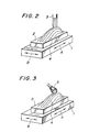
- FIG. 2 is a perspective view illustrating cutting work by a ball end mill.
- a table 1 of a working machine a work 2 fixedly held on the table 1, and a ball end mill 3 for cutting the work 2.
- Machining of the work by such a working machine is performed in the following manner. Namely, the work is cut by shifting the table 1 in a direction indicated by the arrow A while moving the ball end mill 3 up and down. Upon completion of the cutting in the direction A, the table 1 is shifted a little bit in a direction indicated by the arrow B (pick-feed) and cutting is again performed in the direction A. These operations are repeated successively. In this case, cutting tool marks 4 are caused to remain due to the pick-feed on the surface of the work.
- the work machined in such a way cannot be used as a final product. It is therefore necessary to add a further step to remove the cutting tool marks 4 in order to convert the above-machined work into a final product.
- the above-described cutting tool marks 4 are left with a substantially equal interval on the surface of the work and their heights range approximately from 0.1 mm to 0.2 mm. It should be noted that the cutting tool marks 4 shown in Figures 2 and 3 are exaggerated to facilitate their understanding. The heights of these cutting tool marks 4 must be reduced to at least 1 ⁇ m to 0.5 ⁇ m.
- FIG. 3 is a perspective view showing conventional grinding work, in which like elements of structure to those shown in Figure 2 will be designated by like reference numerals.
- Numeral 5 indicates a shafted grinder which is attached to a working machine.
- the profile of the work is in advance stored in a computer or the like and on the basis of the thus- stored information, cutting tool marks 4 are traced by the shafted grinder.
- the heights of the cutting tool marks 4 are as low as several tenths millimeter or so as mentioned above and their sizes and shapes are irregular.
- the working tool may cut the work too deep at certain parts and may be detached from the work at some other parts.
- Figures 4(a), 4(b) and 4(c) are respectively a front view, plan view and side view of a working tool and work. It is necessary to control the relative positional relationship between the working tool and work in order to press the working tool at a constant pressing force against the work as mentioned above. For this purpose, it is necessary to preset coordinate axes. Figures 4(a) through 4(c) show such coordinate axes. In the figures, there are shown a table 1, work 2 and working tool 6. The working tool 6 has a center O of rotation, and it has a profile which contains a spherical surface having a radius r.
- Numeral 7a indicates an arm for rotating the working tool 6
- numeral 7b is a support arm
- numeral 8 designates a load sensor connected rigidly to the support arm 7b
- numeral 9 is a drive source for rotating the arm 7a.
- the drive source 9 is attached rigidly to one end of the load sensor 8, which one end is opposite to the end to which the support arm 7a is rigidly connected.
- a variety of load sensors have been known for the load sensor 8. It is however desirable to use a load sensor of such a type as proposed in Japanese Patent Laid-Open No. 62497/1985 (which corresponds to European Patent Application No. 84200591.0 of April 26, 1984).
- the arm 7b is coupled to an unillustrated main body of a working machine and is rotated and displaced three-dimensionally.
- a coordinate system X-Y-Z has been established with a suitable portion Om of the main body of the working machine being as an origin, while a coordinate system x-y-z is established with the center 0 of rotation of the working tool 6 being as its origin.
- Letter T indicates a point of action (working point) of the working tool 6 on the work 2
- letter F indicates a working reaction force exerted on the working tool 6.
- the table 1 is, in most general forms, turnable about any of three axes which are not contained in the same plane. This function of the table is however omitted in the figures.
- FIG. 5 is an enlarged front view of the working tool 6 and work 2.
- the work 2 working tool 6, working point T, working reaction force F and flat surface P tl on the work 2.
- ⁇ - ⁇ which includes the working point T as its origin, as shown in the figure.
- the ⁇ -axis is placed as a line.passing through the working point T and the center 0 of the working tool 6, while the ⁇ -axis is defined as an intersecting line between the plane P tl , which is perpendicular to the ⁇ -axis, and a plane defined by the feeding direction (the direction of the x-axis) of the working tool 6 and the ⁇ -axis. Since the coordinate system has been established in the above-mentioned manner, the ⁇ -axis is coincided with the z-axis and the ⁇ -axis extends in parallel with the x-axis.
- the magnitude F and direction ⁇ of the working reaction force F change in various ways. Conditions under which the grinding efficiency and the quality of finishing are optimized may be achieved by controlling the magnitude F and direction v of the working reaction force F to their respective optimum values F 0 , ⁇ 0 . In view of this, a control system shown in Figure 6 may be contemplated.
- FIG 6 is a system diagram of a working machine, in which the working machine is applied to a flat work surface.
- a working tool/work system 10 composed of the working tool 6, table 1, work 2 and the like, a load sensor 8 shown in Figures 4(a) and 4(b), and drive and control systems 11 for individual axes.
- the drive and control systems 11 for the respective axes are composed of drive and control systems, which are adapted to control the drive of the working tool 6 in the directions of respective axes on the basis of the X-Y-Z coordinate system, and other drive and control systems for controlling the tiltings ( ⁇ 1' ⁇ 2 , ⁇ 3 ) about the three axes so as to control the relative positions of the working tool 6 and work 2.
- the drive and control systems 11 drive and control the working tool 6 and/or table 1 so as to establish desired relative positions between the working tool 6 and work 2.
- Designated at numeral 12 means a controlling and computing unit for performing prescribed operations in accordance with each detection signal from the load sensor 8.
- components F which is equal to the force component F ⁇ in this case
- F which is equal to the force component F ⁇
- the controlling and computing unit 12 computes, based on the detection signals, such desirable values X,Y of the relative positions X,Y between the working tool 6 and the work 2 that the magnitude F and direction ⁇ should become their respective optimum values F O and ⁇ 0 .
- the values X,Z computed at the controlling and computing unit 12 are then input to the drive and control systems 11 for respective axes.
- the drive and control systems 11 for respective axes change the relative positions in the working tool/work system 10 to new relative positions X,Z.
- the magnitude F and direction ⁇ of the reaction force are maintained respectively at their optimum values F O and ⁇ 0 .
- the working tool 6 is pressed under the constant pressing force against the work 2, whereby to permitting automatic machining without developing breakage or abrupt wearing on the working tool 6 while maintaining the optimum working conditions.
- the operation at the controlling and computing unit 12 will be described in further detail. It is dependent on the material of the work 2 and the material, shape, rotation speed, rotating direction, etc. of the working tool 6 how the working reaction force changes in accordance with a varied depth of cut and a feeding speed. Namely, the working reaction force is not constant. Therefore, it is not possible to show the computing means of the controlling and computing unit 12 in a general form. According to findings obtained through experiments, the direction ⁇ of the working reaction force remains substantially at a constant value ⁇ 0 in the neighbourhood of practical feeding speeds and depths of cut.
- the working reaction force can be controlled if either one of the values F and F ⁇ , which are components of the working reaction force, is detected and the thus-detected value F ⁇ or F ⁇ is controlled to the ⁇ -axis force component F ⁇ 0 or ⁇ -axis force component F ⁇ 0 of the above-described optimum value F O .
- the control algorithm of the controlling and computing unit 12 will hereinafter be described.
- the controlling and computing unit 12 may be adapted to perform an operation in such a way that by paying attention for example only to the normal force component F ⁇ , a value capable of controlling the relative positions of the working tool 6 and work 2 in the direction of the -axis (which is equal to the direction of the z-axis in this case) so as to make the force component F ⁇ approach the optimum value F ⁇ 0 is calculated.
- the speed v ⁇ may for example be chosen to A 1 (F ⁇ - F ⁇ 0 ), in which A is a positive constant, and the optimum value F ⁇ 0 is represented by F O cos ⁇ 0 .
- the speed v ⁇ in the direction of the ⁇ -axis which is equivalent to the feeding direction, is always kept at a constant feeding speed v t
- the velocities v x ,v z in the direction of the x-axis and z-axis are respectively represented as follows:
- the angle can be represented as follow: Since the x-axis and z-axis are respectively parallel to the coordinate axes X and Z of the main body of the working machine, the values X and Z may be calculated on the basis of the outputs from the controlling and computing unit 12 in the above case while supposing
- the above-described control algorithm of the controlling and computing unit 12 is to perform continuous control in the direction of the -axis in accordance with the difference ⁇ F ⁇ between the force component F c and the optimum value F ⁇ 0 .
- the following means may however be employed in order to further simplify the operation and control in the controlling and computing unit 12. Such means will next be described with reference to a block diagram depicted in Figure 7.
- Figure 7 is an enlarged front view of the working tool 6 and work 2, for describing the operation of the controlling and computing unit.
- forces, angle, points, axes, etc. similar to those shown in Figure 5 are identified by like reference letters.
- D 1 - D 5 are vectors indicating the magnitudes and directions of speeds preset with the point O being a center.
- the degrees of difference between the detected force component F and its optimum value F ⁇ 0 are classified into five ranges, and the velocity in each range with which the working tool 6 should move to let F ⁇ coincide with F ⁇ 0 is made correspond to each one of the said five vectors D 1 - D 5 , and thus an x-axis component v x and a z-axis component v z which the controlling and computing unit 12 should output are gained from the vector.
- Velocity components to be obtained when the five ranges are rendered corresponding to the vectors respectively may be summarized as shown in Table 1.
- the value v 0 is a constant value which is chosen from working specification and is close to the ideal feeding speed v f .
- the angle ⁇ is limited discretely to five directions unlike the said means for performing continuous control in the direction of the ⁇ -axis.
- the speeds v x ,vy are limited in advance to the three values 0, v 0 and -v 0 . Therefore, it may be expected that the control may somewhat lack smoothness.
- the cycle time of operations is a very small value. Accordingly, no inconvenience or problem will practically arise even when control is performed by such means.
- the outputs v x ,v Z may each require only three levels which correspond to the values 0, v 0 and -v o .
- the computing system can be simplified to a significant extent.
- the constants which are employed in Table 1 to classify the values F ⁇ are not necessarily limited to the values given in Table 1 but may stand for a variety of suitable values.
- An object of this invention is therefore to provide a profile working machine which can automatically machine a work having a curved surface, the profile of which is not exactly known, without developing breakage or abrupt wearing on a working tool.
- the present invention provides a profile working machine equipped with a support for holding a work in place, a working tool for machining the work and drive and control systems for controlling the relative displacements between the support and working tool and adapted to machine the work into a desired profile, which machine comprises:
- the present invention performs working or machining by tracing the shape of a curved-surface of each work while maintaining the working reaction force, which is exerted to the working tool, at optimum magnitude and direction. It is thus possible to automatically work or machine a work, the exact shape of which is unknown, under ideal working conditions without developing breakage or abrupt wearing on the working tool. Therefore, the working is rendered easy, leading to man power saving of the working and uniform accuracy of working finish. As a result of the working, data on the shape of the work can be collected, whereby making it possible to proceed efficiently with subsequent steps.
- FIG. 1 is a system diagram of a profile working machine according to one embodiment of this invention.
- units of system similar to those illustrated in Figure 6 are indicated by like reference numerals.
- Numeral 8' indicates a load sensor for detecting force components along respective axes and moment components about respective axes.
- Designated at numeral 15 is a controlling and computing unit the structure of which is different from the controlling and computing unit 12 illustrated in Figure 6.
- the controlling and computing unit 15 is composed of a memory 15A for storing data on the shape of a working tool, a system 15B for calculating a working point and tangential plane (which may hereinafter be called “working point/tangential plane calculation system 15B), and a controlling and computing unit 15C for the working point and working reaction force (which may hereinafter be called “working point/working reaction force controlling and computing unit 15C").
- Numeral 16 indicates displacement sensors for detecting displacements of the working tool 6 and the table 1. In the machine of this embodiment, the same coordinate systems X-Y-Z and x-y-z as those shown in Figures 4(a) through 4(c) are employed.
- the load sensor 8 detects the working reaction force F and a moment M (M x ,M y ,M z ) produced by the force components of the working reaction force.
- the working point/tangential plane calculation system 15B is input with the force F and moment M detected by the load sensor 8' as well as the relative positions X,Y,Z (hereinafter represented generally by "X") and relative angles of spatial orientation ⁇ 1 , ⁇ 2 , ⁇ 3 (hereinafter represented generally by”h)") of the working tool 6 and table 1, which relative positions and angles have been detected by the displacement sensors 16, and dimensional data S of the working tool 6 indicated by the memory 15A for storing data on the shape of the working tool. Based on the thus-input information, the working point/tangential plane calculation system 15B determines the coordinate values of the working point T and the tangential plane P t which passes through the working point T and is in contact with the working tool 6.
- the working point/working reaction force controlling and computing unit 15C is fed with the working point T and tangential plane P t determined by the working point/tangential plane calculation system 15B, the force F detected by the load sensor 8' and the outputs X,e) of the displacement sensor 16. Based on the thus-input values, the working point/working reaction force controlling and computing unit 15C computes the relative positions and relative angles of spatial orientation required respectively for the working tool 6 and work 2, and then outputs them as command values X ⁇ ,H ⁇ ) to the drive and control systems 11 for the respective axes.
- the drive and control systems 11 for the respective axes drive and control the working tool 6 and work 2 on the basis of the command values X ⁇ ,H ⁇ ) so that the working tool 6 and work 2 satisfy the above-mentioned desired relative positions and relative angles of spatial orientation.
- the above-mentioned relative positions and relative angles of spatial orientation which are computed at the working point/working reaction force controlling and computing unit 15C, are relative positions and relative angles of spatial orientation which are both required to hold the working point T within the machinable range of the working tool 6 or desirably within a range permitting best working conditions and also to maintain the magnitude and direction of the working reaction force F within the ranges of values (optimum values) capable of satisfying optimum working conditions.
- the working tool 6 is pressed at a constant pressing force against the work 2 even when the work 2 has a three-dimentionally curved surface, to say nothing of a horizontal surface.
- automatic machining can be performed without developing breakage or abrupt wearing on the working tool 6 while maintaining the optimum working conditions.
- Figure 8 is the system diagram of a profile working machine applied to such a surface.
- Figure 9 is an enlarged front view of the working tool 6 and work 2 in the above case.
- similar units of system to those shown in Figure 1 are indicated by like reference numerals.
- the displacement sensor 16 is omitted and the values input to and output from respective units are specifically given.
- Figure 9 illustrates a state in which the working tool 6 having a circular cross-section with the radius of r is machining a tilted surface of the work 2.
- Letter a indicates the angle of tilting of the tilted surface to the horizontal plane.
- FIG. 10(a), 10(b) and 10(c) are respectively an enlarged front view, enlarged plan view and enlarged side view of a working tool and work.
- the working point T (x t ,y t ,z t ) is not on any of the axes and changes three-dimensionally.
- Letter y 0 indicates the distance between the center O of the working tool 6 and the reference point Q of the load sensor 8'.
- Equations (5) to (7) represent relationship which can always be established between the force components F x ,F y ,F z and the moment components M x ,M y ,M z
- Equation (8) represents that the working point T is located on the surface (a spherical surface having a radius r) of the working tool 6. From Equations (6) and (7), the following equations can be derived.
- Equation 11 Introducing Equations (9) and (10) into Equation (8) and solving Equation (8) with respect to x t ,
- Equation 11 supposing the solution of Equation 11 is
- Equation (5),(7) will become unnecessary because they are simplified respectively to the following obvious equations:
- the working point/tangential plane calculation system 15B receives the force components F x , Fz and the moment component M from the load sensor 8' and the radius r of the working tool 6 from the working tool shape data memory 15A, performs an operation in accordance with Equation (20), and then outputs the angle a of tilting of the tangential plane P t to the working point/working reaction force controlling and computing unit 15C.
- ⁇ (the direction relative to the -axis) in which the working tool 6 should be advanced and the speeds v x ,v z at which the working tool 6 should be advanced respectively in the directions of the x-axis and z-axis.
- ⁇ is deemed to be equivalent to ⁇ 0 ( ⁇ ⁇ ⁇ 0 ).
- FIG. 11(a) is an enlarged front view of the working tool and work under the former situation
- Figure 11(b) is an enlarged side view of the same working tool and work under the latter situation.
- letter v indicates the magnitude of the speed at which the working tool 6 should be advanced.
- FIG. 15C is an enlarged front elevation of the working tool and work.
- an angle ( ⁇ + ⁇ ) obtained by adding the input angle a to the angle calculated in accordance with Equation (27) or Equation (30) is classified into 9 ranges.
- the x-axis component v x and z-axis component v z of each of the vectors are obtained.
- Values to be obtained when the nine ranges are rendered corresponding to the vectors respectively in the above manner are given in Table 2.
- the working reaction force F (F x ,F y ,F z ) and the moment M (M x ,M y ,M z ) produced on the basis of the reaction force, which reaction force and moment have been detected by the load sensor 8', as well as data S on the shape of the working tool are input to the working point/tangential plane calculation system 15B, whereby to determine the coordinate values (x t ,x y ,x z ) of the contact point T (working point) between the working tool 6 and work 2.
- the above-described Equation (5) to Equation (7) are established between the respective force components F x ,F y ,F z and moment components M x ,My,M z and the coordinate values of the working point T.
- Equation (8) is also satisfied as the working point T is located on the surface of the working tool 6. Accordingly, the coordinate values (x t ,y t ,z t ) of the working point T can be determined from Equation (5) to Equation (8) as expressed in Equation (13), Equation (14) and Equation (15).
- the tangential plane P t can also be determined as a plane which extends through the working point T and is perpendicular to the line O-T. The above calculations are feasible when the axes of the X-Y-Z coordinate system are respectively kept in parallel with their corresponding axes of the x-y-z coordinate system.
- a cylindrical coordinate system (a coordinate system employed where the relative positions of the working tool 6 and work 2 change in a cylindrical form) is used by way of example, the coordinates of the wording point T and tangential plane P t cannot be determined unless the values X,@) detected by the displacement sensors 16 are used.
- a variety of calculation equations may be contemplated depending for example which axes the coordinate system for the rotary angles ⁇ 1 , ⁇ 2 , ⁇ 3 has its reference axes and when the used coordinate systems are not orthogonal coordinate systems, what relationship should be established between the coordinate systems. It is extremely complex to show such various cases by general equations. Moreover, it is not believed that the present embodiment becomes unclear unless such general equations are given. Therefore, description on such general equations is omitted.
- the working point/working reaction force controlling and computing unit 15C is fed with the coordinate values of the working point T and the tangential plane P t , both determined by the working point/tangential plane calculation system 15B, as well as the reaction force F detected by the load sensor 8' and the relative positions X and relative angles @)of spatial orientation of the working tool 6 and work 2, which positions and angles have been detected by the displacement sensors 16.
- the working point/working reaction force controlling and computing unit 15C calculates the displacements X ⁇ ,H ⁇ ) and velocities , ) which the control systems for the corresponding axes should produce in order to maintain the working point T within a range required for conducting desirable machining and at the same time, in order to maintain the magnitude F and direction ⁇ of the working reaction force of the working tool 6 respectively at the values F 0 , ⁇ 0 while the desirable working conditions are achieved.
- These calculations are performed by means similar to that described in the first specific example.
- the drive and control systems 11 for the respective axes are fed with the values X ⁇ ,H ⁇ ) calculated by the working point/working reaction force controlling and computing unit 15C. They then actuate, in accordance with the thus-ihput values X ⁇ ,H ⁇ ), the servomechanisms of their respective control axes, the number of which corresponds to the degree of freedom of the working machine per se, and realize the actual displacements X ⁇ ,H ⁇ )which are equal to the values X ⁇ ,H ⁇ ) input thereto.
- FIG 13 is an enlarged side view of the working tool, work and table, which are seen in the same direction as in Figure 4(c).
- the table, work and working tool are indicated respectively by numerals 1, 2 and 6.
- the respective coordinates are set in the same manner as those shown in Figures 4(a) through 4(c).
- the figure shows such a case that the working point T is in the course of departing from the machinable range of the working tool 6.
- the working point T is positioned near the central part of the working tool 6 (on the z-axis). It is necessary at least to avoid such situations that the working point T is apart from the working tool 6.
- the rotary system e 1 which has the axis R of the table 1 as its central axis of rotation is turned over an angle of ⁇ 1 .
- the relative angles of spatial orientation between the working tool 6 and work 2 are caused to change, thereby shifting the work reference point W established fixedly on the work 2 to a new point indicated by letter W' and at the same time, also shifting the working point T to a new point indicated by letter T'.
- the above embodiment has been described using the orthogonal coordinate system as a principal coordinate system.
- the cylindrical coordinate system and other suitable coordinate systems may be employed as needed.
- the control of the relative positions of the working tool and work is performed by the working tool whereas the control of the relative angles of their spatial orientation is effected by the table.
- the control of the spatial orientation and that of the positions may conversely be effected by the working tool and table respectively.
- the present invention can be applied to any profile working machine no matter whether the working is grinding or cutting work.
- the working tool is not necessarily limited to a spherical member having the radius r given by way of example in the above embodiment.
- working tools of any shapes may be suitably employed by making use of data on the shapes of the working tools.
- the present invention may be applied to both grinding work and cutting work.
- matter mentioned above to the effect that the direction O of the working reaction force F becomes approximately almost constant has been derived from experimental data on cutting work.
- Such matter, namely, the correlation among parameters which varies in accordance with each working condition can simplify, no matter whether the working is grinding work or cutting work, the structure of the controlling and computing unit to a significant extent provided that the correlation is used as much as possible.
- the degree of a change of the working reaction force F when the relative positions and relative spatial orientations between the working tool and work have changed is great even for slightest changes in the relative positions and relative spatial orientations because the working machine is designed to have a high degree of rigidness.
- the control system of the present invention contains the working tool/work system in its control loop, the above-mentioned high degree of change of the working reaction force renders the loop gain very high and hence oscillates the control system, thereby to create an unstable state.
- the shape and dimensions of the working tool vary in the the cutting work as the cutting work proceeds (where the working tool has for example a spherical surface having a radius r as in the above-described embodiment, the working tool undergoes deformation so that its radius may be reduced or its spherical shape may be deformed into an ellipsoid). If the cutting work should be continued without paying any attention to the above variations in shape and dimensions, it will obviously be impossible to achieve the desired working accuracy.
Landscapes
- Engineering & Computer Science (AREA)
- Human Computer Interaction (AREA)
- Manufacturing & Machinery (AREA)
- Physics & Mathematics (AREA)
- General Physics & Mathematics (AREA)
- Automation & Control Theory (AREA)
- Computing Systems (AREA)
- Theoretical Computer Science (AREA)
- Automatic Control Of Machine Tools (AREA)
- Constituent Portions Of Griding Lathes, Driving, Sensing And Control (AREA)
- Numerical Control (AREA)
- Machine Tool Sensing Apparatuses (AREA)
Abstract
Description
- This invention relates to a profile working machine such as die-finishing cutting machine, ceramics-working cutting machine, three-dimensional milling machine or the like.
- When performing working or machining to form a free-form curved surface on a work such as die machining, the working or machining is in many instances conducted by mounting a ball end mill or th like on an NC milling machine or machining center. After such working or machining is performed, cutting tool marks are caused to remain on the thus-finished die. Hence, it cannot be used as a die without any further machining or treatment. This will next be described with reference to Figure 2.
- Figure 2 is a perspective view illustrating cutting work by a ball end mill. In the drawing, there are shown a table 1 of a working machine, a
work 2 fixedly held on the table 1, and a ball end mill 3 for cutting thework 2. Machining of the work by such a working machine is performed in the following manner. Namely, the work is cut by shifting the table 1 in a direction indicated by the arrow A while moving the ball end mill 3 up and down. Upon completion of the cutting in the direction A, the table 1 is shifted a little bit in a direction indicated by the arrow B (pick-feed) and cutting is again performed in the direction A. These operations are repeated successively. In this case,cutting tool marks 4 are caused to remain due to the pick-feed on the surface of the work. Thus, the work machined in such a way cannot be used as a final product. It is therefore necessary to add a further step to remove thecutting tool marks 4 in order to convert the above-machined work into a final product. Incidentally, the above-describedcutting tool marks 4 are left with a substantially equal interval on the surface of the work and their heights range approximately from 0.1 mm to 0.2 mm. It should be noted that thecutting tool marks 4 shown in Figures 2 and 3 are exaggerated to facilitate their understanding. The heights of thesecutting tool marks 4 must be reduced to at least 1 µm to 0.5 µm. - Conventionally, the above-machined work was manually worked with a shafted grinder held by a hand. Assuming now that one would employ the prior art technique and perform it mechanically, the following machine may be contemplated.
- Figure. 3 is a perspective view showing conventional grinding work, in which like elements of structure to those shown in Figure 2 will be designated by like reference numerals. Numeral 5 indicates a shafted grinder which is attached to a working machine. The profile of the work is in advance stored in a computer or the like and on the basis of the thus- stored information,
cutting tool marks 4 are traced by the shafted grinder. However, the heights of thecutting tool marks 4 are as low as several tenths millimeter or so as mentioned above and their sizes and shapes are irregular. Thus, it is impossible to finish the surface of the work into any sufficiently smooth surface if one relies upon the accuracy achieved merely by storing the profile of thework 2 in a computer. Namely, the working tool may cut the work too deep at certain parts and may be detached from the work at some other parts. - The above method is accompanied by another serious drawback that it cannot be applied unless profile data of each work are available in advance. It has thus been usual to carry out the removal of
cutting tool marks 4 manually, because the automatic grinding machine conceivable from the prior art is accompanied by such serious drawbacks as mentioned above and no other suitable automatic grinding machine is available. This applies not only to the above-described machining work but also to general profile-machining work. Such machining work has prevented full automation of machining steps, resulting in the need for lots of man power and time. - In order to solve such problems of the prior art techniques and enable automatic machining, the present inventors conceived that the above machining could be achieved by machining the surface of a work while pressing a working tool at a constant pressing force against the surface of the work and tracing the profile of the surface of the work. With a view toward materializing the above idea, the following study was carried out. The study will next be described with reference to Figures 4(a), 4(b) and 4(c).
- Figures 4(a), 4(b) and 4(c) are respectively a front view, plan view and side view of a working tool and work. It is necessary to control the relative positional relationship between the working tool and work in order to press the working tool at a constant pressing force against the work as mentioned above. For this purpose, it is necessary to preset coordinate axes. Figures 4(a) through 4(c) show such coordinate axes. In the figures, there are shown a table 1,
work 2 andworking tool 6. Theworking tool 6 has a center O of rotation, and it has a profile which contains a spherical surface having a radius r. Numeral 7a indicates an arm for rotating theworking tool 6,numeral 7b is a support arm whereasnumeral 8 designates a load sensor connected rigidly to thesupport arm 7b andnumeral 9 is a drive source for rotating thearm 7a. Thedrive source 9 is attached rigidly to one end of theload sensor 8, which one end is opposite to the end to which thesupport arm 7a is rigidly connected. A variety of load sensors have been known for theload sensor 8. It is however desirable to use a load sensor of such a type as proposed in Japanese Patent Laid-Open No. 62497/1985 (which corresponds to European Patent Application No. 84200591.0 of April 26, 1984). Thearm 7b is coupled to an unillustrated main body of a working machine and is rotated and displaced three-dimensionally. As illustrated in the figures, a coordinate system X-Y-Z has been established with a suitable portion Om of the main body of the working machine being as an origin, while a coordinate system x-y-z is established with the center 0 of rotation of theworking tool 6 being as its origin. Letter T indicates a point of action (working point) of theworking tool 6 on thework 2, whereas letter F indicates a working reaction force exerted on theworking tool 6. Incidentally, the table 1 is, in most general forms, turnable about any of three axes which are not contained in the same plane. This function of the table is however omitted in the figures. - Description will next be made on grinding work where the surface of the work is flat. Figure 5 is an enlarged front view of the
working tool 6 andwork 2. In the figure, there are shown thework 2,working tool 6, working point T, working reaction force F and flat surface Ptl on thework 2. Let's now establish a force coordinate system ξ-ζ, which includes the working point T as its origin, as shown in the figure. Namely, the ζ-axis is placed as a line.passing through the working point T and the center 0 of theworking tool 6, while the ξ-axis is defined as an intersecting line between the plane Ptl, which is perpendicular to the ξ-axis, and a plane defined by the feeding direction (the direction of the x-axis) of theworking tool 6 and the ξ-axis. Since the coordinate system has been established in the above-mentioned manner, the ξ-axis is coincided with the z-axis and the ξ-axis extends in parallel with the x-axis. The coordinate system ξ-ζ has been established in the above-mentioned manner in order to handle the ξ-axis force component Fξ of the working reaction force F as the tangential force component of the grinding work, the ξ-axis force component F as a normal force component, and an angle ψ (ψ = tan-1 Fξ /Fζ ) as the direction of the reaction force. It is hence possible to keep working conditions under optimum conditions by controlling these tangential force component Fξ, normal force component Fζ and angle ψ at suitable values. - By the way, in grinding work, the magnitude F and direction ψ of the working reaction force F change in various ways. Conditions under which the grinding efficiency and the quality of finishing are optimized may be achieved by controlling the magnitude F and direction v of the working reaction force F to their respective optimum values F0, ψ0. In view of this, a control system shown in Figure 6 may be contemplated.
- Figure 6 is a system diagram of a working machine, in which the working machine is applied to a flat work surface. In the figure, there are shown a working tool/
work system 10 composed of theworking tool 6, table 1,work 2 and the like, aload sensor 8 shown in Figures 4(a) and 4(b), and drive and control systems 11 for individual axes. The drive and control systems 11 for the respective axes are composed of drive and control systems, which are adapted to control the drive of theworking tool 6 in the directions of respective axes on the basis of the X-Y-Z coordinate system, and other drive and control systems for controlling the tiltings (θ1' θ2, θ3) about the three axes so as to control the relative positions of theworking tool 6 andwork 2. The drive and control systems 11 drive and control theworking tool 6 and/or table 1 so as to establish desired relative positions between theworking tool 6 and work 2. Designated atnumeral 12 means a controlling and computing unit for performing prescribed operations in accordance with each detection signal from theload sensor 8. - When the
working tool 6 is being driven in the direction x as illustrated in Figure 5, components F (which is equal to the force component Fξ in this case) and F (which is equal to the force component Fζ) of a reaction force exerted at the working point T are detected by theload sensor 8 and its detection signals are output to the controlling andcomputing unit 12. The controlling andcomputing unit 12 then computes, based on the detection signals, such desirable values X,Y of the relative positions X,Y between theworking tool 6 and thework 2 that the magnitude F
and direction ψ
should become their respective optimum values FO and ψ0. The values X,Z computed at the controlling andcomputing unit 12 are then input to the drive and control systems 11 for respective axes. In accordance with the values X̅,Z̅, the drive and control systems 11 for respective axes change the relative positions in the working tool/work system 10 to new relative positions X,Z. As a result, the magnitude F and direction ψ of the reaction force are maintained respectively at their optimum values FO and ψ0. Hence, the workingtool 6 is pressed under the constant pressing force against thework 2, whereby to permitting automatic machining without developing breakage or abrupt wearing on the workingtool 6 while maintaining the optimum working conditions. - Here, the operation at the controlling and
computing unit 12 will be described in further detail. It is dependent on the material of thework 2 and the material, shape, rotation speed, rotating direction, etc. of the workingtool 6 how the working reaction force changes in accordance with a varied depth of cut and a feeding speed. Namely, the working reaction force is not constant. Therefore, it is not possible to show the computing means of the controlling andcomputing unit 12 in a general form. According to findings obtained through experiments, the direction ψ of the working reaction force remains substantially at a constant value ψ0 in the neighbourhood of practical feeding speeds and depths of cut. However, for such practical feeding speeds and depths of cut, only the magnitude F of the working reaction force varies in accordance with the details of each grinding specification as values F',F" as shown by broken lines in Figure 5. Therefore, the working reaction force can be controlled if either one of the values F and Fξ, which are components of the working reaction force, is detected and the thus-detected value Fζ or Fξ is controlled to the ζ-axis force component Fζ0 or ξ-axis force component Fξ0 of the above-described optimum value FO. Based on the above concept, the control algorithm of the controlling andcomputing unit 12 will hereinafter be described. - The controlling and
computing unit 12 may be adapted to perform an operation in such a way that by paying attention for example only to the normal force component Fζ, a value capable of controlling the relative positions of the workingtool 6 andwork 2 in the direction of the -axis (which is equal to the direction of the z-axis in this case) so as to make the force component Fζ approach the optimum value Fζ0 is calculated. For this purpose, the speed vξ in the direction of the -axis may be chosen in such a way that it either increases or decreases depending on the difference Δ Fξ (ΔF ξ = Fξ - Fξ0 ) between the force component Fξ and the optimum value Fξ0. The speed vξ may for example be chosen to A1(Fξ - Fξ0), in which A is a positive constant, and the optimum value Fξ0 is represented by FOcos ψ0. Supposing that the speed vξ in the direction of the ξ-axis, which is equivalent to the feeding direction, is always kept at a constant feeding speed vt, the velocities vx,vz in the direction of the x-axis and z-axis are respectively represented as follows:
Furthermore, supposing that the advancing direction of the central point O of the workingtool 6 is at an angle φ as measured from the positive direction of the x-axis, the angle can be represented as follow:
Since the x-axis and z-axis are respectively parallel to the coordinate axes X and Z of the main body of the working machine, the values X and Z may be calculated on the basis of the outputs from the controlling andcomputing unit 12 in the above case while supposing X = vx and Z = vZ. - The above-described control algorithm has been given merely by way of example. Various other methods may also be contemplated. Although the speed v& in the feeding direction is set as the constant value vf in the above-described method, it may also be possible to employ such a way of thinking that the absolute value of speed of the working
tool 6 at each moment upon proceeding with machining while moving the workingtool 6 slightly up and down in accordance with the profile of thework 2 is chosen as an ideal feeding speed vf (which may be determined experimentally). In this case, the speeds vz,vx may be chosen as follows:
When the speeds vz,vx are chosen as described
above, the angle φ can be expressed as follow:
- The above-described control algorithm of the controlling and
computing unit 12 is to perform continuous control in the direction of the -axis in accordance with the difference ΔFξ between the force component Fc and the optimum value Fξ0. The following means may however be employed in order to further simplify the operation and control in the controlling andcomputing unit 12. Such means will next be described with reference to a block diagram depicted in Figure 7. - Figure 7 is an enlarged front view of the working
tool 6 andwork 2, for describing the operation of the controlling and computing unit. In the figure, forces, angle, points, axes, etc. similar to those shown in Figure 5 are identified by like reference letters. D1 - D5 are vectors indicating the magnitudes and directions of speeds preset with the point O being a center. In this simplified means, the degrees of difference between the detected force component F and its optimum value Fξ0 are classified into five ranges, and the velocity in each range with which the workingtool 6 should move to let Fξ coincide with Fξ0 is made correspond to each one of the said five vectors D1 - D5, and thus an x-axis component vx and a z-axis component vz which the controlling andcomputing unit 12 should output are gained from the vector. Velocity components to be obtained when the five ranges are rendered corresponding to the vectors respectively may be summarized as shown in Table 1.
- In Table 1, the value v0 is a constant value which is chosen from working specification and is close to the ideal feeding speed vf. In the above means, the angle φ is limited discretely to five directions unlike the said means for performing continuous control in the direction of the ξ-axis. Furthermore, the speeds vx,vy are limited in advance to the three values 0, v0 and -v0. Therefore, it may be expected that the control may somewhat lack smoothness. However, the cycle time of operations is a very small value. Accordingly, no inconvenience or problem will practically arise even when control is performed by such means. In digital control making use of a microcomputer, the outputs vx,vZ may each require only three levels which correspond to the values 0, v0 and -vo. Thus, the computing system can be simplified to a significant extent. The constants which are employed in Table 1 to classify the values Fξ are not necessarily limited to the values given in Table 1 but may stand for a variety of suitable values.
- The foregoing is the matter studied by the present inventors. In the above-described manner, it will become possible to press the working
tool 6 at a constant pressing force against the surface of the work and to perform automatic machining without developing breakage or abrupt wearing on the workingtool 6 while maintaining optimum machining conditions. However, the above control is fundamentally effective only where the surface of thework 2 is a flat surface. It is accompanied by a problem that it cannot be successfully applied when the surface of thework 2 is a curved-surface. - The present invention has been completed with the foregoing in view. An object of this invention is therefore to provide a profile working machine which can automatically machine a work having a curved surface, the profile of which is not exactly known, without developing breakage or abrupt wearing on a working tool.
- In order to attain the above-described object, the present invention provides a profile working machine equipped with a support for holding a work in place, a working tool for machining the work and drive and control systems for controlling the relative displacements between the support and working tool and adapted to machine the work into a desired profile, which machine comprises:
- a load sensor for detecting each force and moment to be developed between the working tool and the work;
- a first computing unit for computing a working point and a tangential plane extending through the working point and in contact with the working tool, on the basis of the force and moment detected by the load sensor; and
- a second computing unit for computing, based on the working point and tangential plane computed by the first computing unit and the forces detected by the load sensor, the values of the relative displacements between the working tool and the support in order to keep the magnitude and the direction of a reaction force exerted on the working tool on predetermined values.
- The present invention performs working or machining by tracing the shape of a curved-surface of each work while maintaining the working reaction force, which is exerted to the working tool, at optimum magnitude and direction. It is thus possible to automatically work or machine a work, the exact shape of which is unknown, under ideal working conditions without developing breakage or abrupt wearing on the working tool. Therefore, the working is rendered easy, leading to man power saving of the working and uniform accuracy of working finish. As a result of the working, data on the shape of the work can be collected, whereby making it possible to proceed efficiently with subsequent steps.
- The above and other objects, features and advantages of the present invention will become apparent from the following description and the appended claims, taken in conjunction with the accompanying drawings, in which:
- Figure 1 is a system diagram of a profile working machine according to one embodiment of this invention;
- Figure 2 is a perspective view showing cutting work by a ball end mill;
- Figure 3 is a perspective view showing conventional grinding work;
- Figures 4(a), 4(b) and 4(c) are respectively front, plan and side views of a working tool and a work;
- Figure 5 is an enlarged front view of the working tool and work;
- Figure 6 is a system diagram of a working machine where the surface of the work is flat;
- Figure 7 is an enlarged front view of the working tool and work for explaining the operation of a controlling and computing unit;
- Figure 8 is a system diagram of the profile working machine when the surface of the work changes two-dimensionally;
- Figure 9 is an enlarged front view of the working tool and work when the surface of the work changes two-dimensionally;
- Figures 10(a), 10(b) and 10(c) are respectively enlarged front, plan and side views of the working tool and work when the surface of the work changes three-dimensionally;
- Figure 11(a) and 11(b) and Figure 12 are enlarged front views of the working tool and work for explaining the operation of the controlling and computing unit depicted in Figure 8; and
- Figure 13 is an enlarged front view of the working tool and work for explaining the operation of the controlling and computing unit shown in Figure 1.
- The present invention will hereinafter be described on the basis of certain embodiments of this invention which are shown in the accompanying drawings.
- Figure 1 is a system diagram of a profile working machine according to one embodiment of this invention. In the figure, units of system similar to those illustrated in Figure 6 are indicated by like reference numerals. Numeral 8' indicates a load sensor for detecting force components along respective axes and moment components about respective axes. Designated at
numeral 15 is a controlling and computing unit the structure of which is different from the controlling andcomputing unit 12 illustrated in Figure 6. The controlling andcomputing unit 15 is composed of amemory 15A for storing data on the shape of a working tool, asystem 15B for calculating a working point and tangential plane (which may hereinafter be called "working point/tangentialplane calculation system 15B), and a controlling andcomputing unit 15C for the working point and working reaction force (which may hereinafter be called "working point/working reaction force controlling andcomputing unit 15C").Numeral 16 indicates displacement sensors for detecting displacements of the workingtool 6 and the table 1. In the machine of this embodiment, the same coordinate systems X-Y-Z and x-y-z as those shown in Figures 4(a) through 4(c) are employed. - Let's now suppose that the surface of the
work 2 is being machined by the workingtool 6. When the relative positions or relative angles of spatial orientation of the workingtool 6 andwork 2 vary, the working reaction force F and working point T (shown in Figures 4(a) through 4(c)), which are determined by such parameters as the rigidity of the workingtool 6,work 2 and the main body of the working machine. Here, theload sensor 8 detects the working reaction force F and a moment M (Mx,My,Mz) produced by the force components of the working reaction force. The working point/tangentialplane calculation system 15B is input with the force F and moment M detected by the load sensor 8' as well as the relative positions X,Y,Z (hereinafter represented generally by "X") and relative angles of spatial orientation θ1,θ2,θ3 (hereinafter represented generally by"ⓗ)") of the workingtool 6 and table 1, which relative positions and angles have been detected by thedisplacement sensors 16, and dimensional data S of the workingtool 6 indicated by thememory 15A for storing data on the shape of the working tool. Based on the thus-input information, the working point/tangentialplane calculation system 15B determines the coordinate values of the working point T and the tangential plane Pt which passes through the working point T and is in contact with the workingtool 6. The working point/working reaction force controlling andcomputing unit 15C is fed with the working point T and tangential plane Pt determined by the working point/tangentialplane calculation system 15B, the force F detected by the load sensor 8' and the outputs X,e) of thedisplacement sensor 16. Based on the thus-input values, the working point/working reaction force controlling andcomputing unit 15C computes the relative positions and relative angles of spatial orientation required respectively for the workingtool 6 andwork 2, and then outputs them as command values X̅,Ⓗ̅) to the drive and control systems 11 for the respective axes. Thereafter, the drive and control systems 11 for the respective axes drive and control the workingtool 6 andwork 2 on the basis of the command values X̅,Ⓗ̅) so that the workingtool 6 andwork 2 satisfy the above-mentioned desired relative positions and relative angles of spatial orientation. The above-mentioned relative positions and relative angles of spatial orientation, which are computed at the working point/working reaction force controlling andcomputing unit 15C, are relative positions and relative angles of spatial orientation which are both required to hold the working point T within the machinable range of the workingtool 6 or desirably within a range permitting best working conditions and also to maintain the magnitude and direction of the working reaction force F within the ranges of values (optimum values) capable of satisfying optimum working conditions. - Owing to the above structure, the working
tool 6 is pressed at a constant pressing force against thework 2 even when thework 2 has a three-dimentionally curved surface, to say nothing of a horizontal surface. Thus, automatic machining can be performed without developing breakage or abrupt wearing on the workingtool 6 while maintaining the optimum working conditions. - In order to permit clearer understanding of the above-described embodiment, further description will be made by giving the following some specific examples.
- First of all, description will be made on such a case that a surface of the
work 2, which surface is to be machined, changes two-dimensionally in the plane defined by the coordinate system x-z. Figure 8 is the system diagram of a profile working machine applied to such a surface. Figure 9 is an enlarged front view of the workingtool 6 andwork 2 in the above case. In Figure 8, similar units of system to those shown in Figure 1 are indicated by like reference numerals. In this case, thedisplacement sensor 16 is omitted and the values input to and output from respective units are specifically given. - Figure 9 illustrates a state in which the working
tool 6 having a circular cross-section with the radius of r is machining a tilted surface of thework 2. Letter a indicates the angle of tilting of the tilted surface to the horizontal plane. Furthermore, the coordinate values of the working point T are xt, Yt and zt in which yt = 0). Let's now suppose that the machining work is moving from the horizontal surface to the tilted surface. When the optimum working conditions are maintained on the horizontal surface as shown in Figure 5, the working reaction force has the magnitude FO and direction ψ0. When the machining work has moved from the above state to the tilted surface, the coordinate axes ξ, ζ which pass through the working point T are also tilted respectively over the angle a and the working reaction force F has a direction tilted over the angle ψ0 relative to the the ξ-axis which has already been tilted over the angle a. At this time, the magnitude and direction of the reaction force F change around the magnitude FO and direction ψ0. With respect to the control algorithm in this case, it is only necessary to take into consideration that the coordinate system ξ-ζ is tilted over the angle a relative to the coordinate system x-z. The specific example illustrated in Figure 8 is constructed by making use of practical means which take into account the relation in magnitude between the force component Fξ and the optimum value Fξ0 on the basis of a fact experimentally confirmed that the direction ψ remains substantially around the constant value ψ0. - The operation of the above specific example may be understood more readily when explained by means of numerical formulae. For this purpose, a general analysis will first be made on machining work on a curved surface, namely, on a worked surface which changes three-dimensionally. Thereafter, conditions will be given for profile-machining work in which the worked surface changes two-dimensionally. Figures 10(a), 10(b) and 10(c) are respectively an enlarged front view, enlarged plan view and enlarged side view of a working tool and work. The working point T (xt,yt,zt) is not on any of the axes and changes three-dimensionally. Letter y0 indicates the distance between the center O of the working
tool 6 and the reference point Q of the load sensor 8'. Representing x-axis, y-axis and z-axis force components and x-axis, y-axis and z-axis moments, which are both output from the load sensor 8',.by Fx, Fy and Fz and Mx, M and Mz respectively, the following equations can be established.


- Among the above equations, Equations (5) to (7) represent relationship which can always be established between the force components Fx ,Fy ,Fz and the moment components Mx,My,Mz, whereas Equation (8) represents that the working point T is located on the surface (a spherical surface having a radius r) of the working
tool 6. From Equations (6) and (7), the following equations can be derived. -


Here, supposing
the solution of Equation 11 is
- Introducing Equation (13) into Equations (9) and (10),


- Based on the force components and moment components detected by the load sensor 8', it is possible to determine the coordinate values (xt,yt,zt) of the working point T shown in Figures 10(a) through 10(c). In each of Equations (13) to (15), one of the double symbol ± indicates an actual solution and the other symbol indicates the coordinate value of an imaginary point where a plane parallel to the tangential plane P t contacts the spherical surface of the working
tool 6 except for the working point T. Unless the numerical values of the force components Fx, F and the like are determined, it is unable to tell which one of the double symbol indicates an actual solution. - Here, returning again to the two-dimensional curved surface shown in Figure 9, a further discussion will be made. Since there are conditions of Fy = 0 and yt ≡ 0 in this case, Equation (5),(7) will become unnecessary because they are simplified respectively to the following obvious equations:

- This means that the moment components Mx,My can be calculated from the force components Fx,Fz and distance y0 without need for detecting them specifically. In this case, Equations (6) and (8) have significance. Equation (6) is


- From Equations (16) and (17) or introducing Fy = 0 and y t = 0 into Equations (13) to (15), the coordinate values (xt,zt) of the working point T shown in Figure 9 are expressed as follows:


- In the state depicted in Figure 9, F > 0 and Fx < 0. Accordingly, the negative symbol (-) out of the double symbol indicates the coordinate values of the working point T.
- Here, the angle a of tilting is to be determined. From Figure 9,
-

tool 6, namely, the tangential plane Pt can be determined. - Where the working point T is always located on lines extending in the feeding direction (in the direction of the i-axis in this case) as depicted in Figure 9, control of the working point T is unnecessary and mere control of the working reaction force F is sufficient.
- From the foregoing explanation, the working point/tangential
plane calculation system 15B receives the force components Fx,Fz and the moment component M from the load sensor 8' and the radius r of the workingtool 6 from the working toolshape data memory 15A, performs an operation in accordance with Equation (20), and then outputs the angle a of tilting of the tangential plane Pt to the working point/working reaction force controlling andcomputing unit 15C. - The operation performed by the working point/working reaction force controlling and
computing unit 15C will next be described. In the case shown in Figure 9, the control of the working point T is not necessary and the control of the working reaction force F is sufficient as mentioned above. Accordingly, the force components Fx,Fz are input from the load sensor 8'. Based on these force components Fx,Fz and the above-input angle a of tilting which indicates the tangential plane Pt, the following operation is performed. First of all, the respective force components Fξ,Fζ on the coordinate system ξ- tare determined in Figure 9. Using a general equation for coordinate transformation upon rotating the coordinate axes clockwise over the angle a while sharing the same origin, they can be determined in accordance with the following equations:

- Here, the direction ψ of the reaction force measured from the ξ-axis is

- Based on the thus-determined force component Fξ and direction ψ, operations are performed to determine the values X,Z which allow the force component Ft and direction ψ to have their respective optimum values Fξ, ψ0. As already mentioned in the description of the controlling and
computing unit 12 shown in Figure 6, the above operations were controlled in such a way that when Fξ÷ Fξ0, the workingtool 6 advanced in the direction φ = 0. Here, it is however necessary to calculate the outputs X,Z which causes the workingtool 6 to advance in the direction φ = α, that is, the direction extending along the surface to be worked. Hereinafter, the direction φ (the direction relative to the -axis) in which the workingtool 6 should be advanced and the speeds vx,vz at which the workingtool 6 should be advanced respectively in the directions of the x-axis and z-axis will be determined. However, similar to the above-described case, ψ is deemed to be equivalent to ψ0 (ψ ÷ ψ0). - When determining these values φ, v and v in the above case, the discussion was made separately under two situations, one considering the feeding speed vf to be always constant in the direction of the ξ-axis and the other considering the feeding speed vf as a constant momentary feeding speed. Following the same approach, the present case will also be discussed separately under the above-mentioned two situations. Figure 11(a) is an enlarged front view of the working tool and work under the former situation, while Figure 11(b) is an enlarged side view of the same working tool and work under the latter situation. In each of the figures, letter v indicates the magnitude of the speed at which the working
tool 6 should be advanced. - First of all, general formulae for determining the components vx,vz on the x-z coordinate system from the components vξ, vζ on the ξ-ζ coordinate system are represented as follows:

- Then, the values vx,vz,φ under the former situation depicted in Figure 11(a) are now determined. Since vξ ≡vf, these values are represented as follows from Equations (1), (22) and (24) and the relationship shown in Figure 11(a):


- On the other hand, the values vx,vz,φ under the latter situation illustrated in Figure 11(b) are next determined. From Equations (3), (22) and (24) and the relationship shown in Figure 11(b), these values can be expressed as follows:


Whichever the situation is, it is only necessary to calculate the values X̅,Z̅ as outputs from the working point/working reaction force controlling andcomputing unit 15C by considering X and Z to be equal respective- ly to vx and vz (X = vx, Z = v Z). - Let's now compare the former situation and the latter situation with each other. No big difference arises between the situations when the tilted surface of the angle a of tilting changes gradually. Where the tilted surface has such a complex shape that its curvature changes significantly at a given point in the course of machining, a big difference arises between both situations. In such a case, the working speed along the profile of the work can be always kept at the value vf under the latter situation. Accordingly, most ideal working conditions can be obtained when the value vf is chosen as an ideal feeding speed. By the way, both of the above methods have been given as mere examples of various methods. Basically speaking, any methods may be employed so long as the locus of the working
tool 6 can be controlled so as to maintain the magnitude F and direction ψ of the working reaction force at their respective optimum values. - The operation by the working point/working reaction force controlling and
computing unit 15C has been described above. In this case, it is also possible to employ simplified means similar to the operation at the previously-described controlling andcomputing unit 12. This means will next be described with reference to Figure 12 and Table 2. Figure 12 is an enlarged front elevation of the working tool and work. In the figure, D11, D12, D13' D14, D15 (= -D11), -D12, D13 and -D14 are vectors which indicate the magnitudes and directions of speeds preset about the point 0. They are equivalent to the vectors D1 - D 5 shown in Figure 7. In the simplified means, an angle ( φ + α) obtained by adding the input angle a to the angle calculated in accordance with Equation (27) or Equation (30) is classified into 9 ranges. By making these 9 ranges correspond to the respective vectors, the x-axis component vx and z-axis component vz of each of the vectors are obtained. Values to be obtained when the nine ranges are rendered corresponding to the vectors respectively in the above manner are given in Table 2. -

- The working point/working reaction force controlling and
computing unit 15C receives the values Fx,Fz, α and then calculates continuously the value φ in accordance with Equation (27) or (30). Description will now be made on a case in which Equation (30) is to be used. Supposing first of all that A1 is chosen to be vf/Fξ0 which is considered to be a reasonable value (A1 = vf/Fξ0), the value t will fall within the range of from -90° to 90° (-90° ≤ φ ≤ 90°) provided that the force component Fξ is controlled within the range of from 0 to 2Fξ0 (0 ≤ Fξ ≤ 2Fξ0). Even if Fξ should become greater than 2Fξ0 (F > 2Fξ0), there will be no problem from the viewpoint of control if the value φ is defined in advance to be 90° (φ = 90°) throughout the range. Since the value a is normally from -90° to 90° (exclusive, i.e., -90° < a < 90°), the angle (φ + a) falls between -180° and 180° (exclusive, i.e, -180° < φ + a < 180°). The vector D0 indicated by a two-dot line in Figure 12 should be the most ideal advancing direction for a calculated angle (φ + a). It is necessary to choose the direction Di having a classified advancing direction close to the vector D0, D14 in the case of Figure 12. The classification has been coarsely made 45° by 45° and the values vx,vz are each limited to the three- values 0,v0,-v0. However, smooth control is still feasible without encountering any problems from the viewpoint of control because the cycle time of the operation is very small as mentioned above. Since the working point/working reaction force controlling andcomputing unit 15C outputs simply the above-mentioned three values only, the computing system can be considerably simplified. - As a still simpler method, it may also be contemplated to determine first of all the angle (which will be referred to as "φ1") shown in Table 1, then to judge in which angle range of Table 2 the angle (φ1+ a) is contained, and finally to choose the advancing direction Di of the working
tool 6. In such a method, the value of the force component Fξ is however discretely divided upon determination of the angle φ1 and is further divided discretely upon determination of the angle (ml + a). Therefore, discrete classification is effected twice. Therefore, a direction to be obtained in the above-described two-step operation may deviate as much as about 45° or so at the maximum from its corresponding ideal direction which can be obtained through a continuous operation. Accordingly, use of the above-described means is a method inferior to the previously-described method. However, it is still usable for actual applications. - Description has been made on a case, that is, the first specific example of the present embodiment, which specific example the worked surface of the
work 2 changed two-dimensionally within a plane of the x-z coordinate system. The second specific example of this invention will next be described. - As the second specific example, description will be made on a case in which the worked surface of the
work 2 changes three-dimensionally. In this case, the profile working machine depicted in Figure 1 is used. Here, the relationship between the workingtool 6 andwork 2 will be in such state as shown in Figures 10(a) through 10(c). In the course of the above-described discussion of the first specific example, a general analysis has already been made on the machining work on a curved-surface which changes three-dimensionally. Therefore, making use of the general analysis, the profile working machine shown in Figure 1 will be described in the present specific example. - The working reaction force F (Fx,Fy,Fz) and the moment M (Mx,My,Mz) produced on the basis of the reaction force, which reaction force and moment have been detected by the load sensor 8', as well as data S on the shape of the working tool are input to the working point/tangential
plane calculation system 15B, whereby to determine the coordinate values (xt,xy,xz) of the contact point T (working point) between the workingtool 6 andwork 2. Namely, the above-described Equation (5) to Equation (7) are established between the respective force components Fx,Fy,Fz and moment components Mx,My,Mz and the coordinate values of the working point T. Furthermore, Equation (8) is also satisfied as the working point T is located on the surface of the workingtool 6. Accordingly, the coordinate values (xt,yt,zt) of the working point T can be determined from Equation (5) to Equation (8) as expressed in Equation (13), Equation (14) and Equation (15). In addition, the tangential plane Pt can also be determined as a plane which extends through the working point T and is perpendicular to the line O-T. The above calculations are feasible when the axes of the X-Y-Z coordinate system are respectively kept in parallel with their corresponding axes of the x-y-z coordinate system. When the relative angles Ⓗ) (θ1,θ2,θ3) of spatial orientation between the workingtool 6 andwork 2 are changed or instead of the orthogonal coordinate system, a cylindrical coordinate system (a coordinate system employed where the relative positions of the workingtool 6 andwork 2 change in a cylindrical form) is used by way of example, the coordinates of the wording point T and tangential plane Pt cannot be determined unless the values X,@) detected by thedisplacement sensors 16 are used. In such a case, a variety of calculation equations may be contemplated depending for example which axes the coordinate system for the rotary angles θ1,θ2,θ3 has its reference axes and when the used coordinate systems are not orthogonal coordinate systems, what relationship should be established between the coordinate systems. It is extremely complex to show such various cases by general equations. Moreover, it is not believed that the present embodiment becomes unclear unless such general equations are given. Therefore, description on such general equations is omitted. - The working point/working reaction force controlling and
computing unit 15C is fed with the coordinate values of the working point T and the tangential plane Pt, both determined by the working point/tangentialplane calculation system 15B, as well as the reaction force F detected by the load sensor 8' and the relative positions X and relative angles @)of spatial orientation of the workingtool 6 andwork 2, which positions and angles have been detected by thedisplacement sensors 16. On the basis of these values, the working point/working reaction force controlling andcomputing unit 15C calculates the displacements X̅,Ⓗ̅) and velocities

tool 6 respectively at the values F0,ψ0 while the desirable working conditions are achieved. These calculations are performed by means similar to that described in the first specific example. In usual cases except for such a simple case as defined by the X-Y-Z and x-y-z coordinate systems in which the coordinate axes of the main body of the working machine are parallel to the corresponding coordinate axes of the working tool, it is however necessary, different from the first specific example, to perform operations inclusive additionally of the control of the working point T on the basis of the value T determined by the working point/tangentialplane calculation system 15B and the values X,Ⓗ)detected by thedisplacement sensors 16. This operation which is performed to control the working point T will next be described as the third specific example. - The drive and control systems 11 for the respective axes are fed with the values X̅,Ⓗ̅) calculated by the working point/working reaction force controlling and
computing unit 15C. They then actuate, in accordance with the thus-ihput values X̅,Ⓗ̅), the servomechanisms of their respective control axes, the number of which corresponds to the degree of freedom of the working machine per se, and realize the actual displacements X̅,Ⓗ̅)which are equal to the values X̅,Ⓗ̅) input thereto. - By constructing in the above-described manner, it is always possible to keep the working conditions within their respective optimum ranges without causing the working point T to depart from the machinable range of the working
tool 6 even if thework 2 contains for example a portion at which its shape changes extremely. - Next, a simple example of the working point control and calculation which are performed by the working point/working reaction force controlling and
computing unit 15C as mentioned above will be described. - Figure 13 is an enlarged side view of the working tool, work and table, which are seen in the same direction as in Figure 4(c). In the figure, the table, work and working tool are indicated respectively by
numerals tool 6. By the way, where the workingtool 6 has such configurations as illustrated in the figure, it is desirous that the working point T is positioned near the central part of the working tool 6 (on the z-axis). It is necessary at least to avoid such situations that the working point T is apart from the workingtool 6. For this purpose, it is desirous to keep the working point T in the (x-z) plane, in other words, to keep the coordinate value Yt at 0. For practical applications, it is however not necessary to satisfy yt = 0. It is sufficient so long as the coordinate values yt falls within a permissible range. - In order to shift the coordinate value yt of the working point T to 0 as mentioned above, the rotary system e1 which has the axis R of the table 1 as its central axis of rotation is turned over an angle of Δθ1. By doing so, the relative angles of spatial orientation between the working
tool 6 andwork 2 are caused to change, thereby shifting the work reference point W established fixedly on thework 2 to a new point indicated by letter W' and at the same time, also shifting the working point T to a new point indicated by letter T'. By the way, it is desirable from the idealistic viewpoint to allow the rotary system θ1 to turn about the point T because such an arrangement does not cause the movement of the point T to the point T' by the rotation. It is however difficult to achieve such a structure from the viewpoint of mechanism designing. In fact, it is impossible to achieve such a structure because the point T changes moment by moment. Then, the center 0 of the workingtool 6 is shifted to the new point 0' so that thework 2 can be machined at the new point T' by the workingtool 6 in its lowest position. For this purpose, the present center 0 (Y1,Z1) is moved to the new center 0' (y2'z2) by their respective differences AY and AZ within the plane defined by the coordinate axes Y and Z in the X-Y-Z coordinate system which has been fixedly established on the main body of the working machine. The outputs resulted solely from the above operation are now represented by values Yt,Zt,θlt. By substituting these values for the axes Y,Z,e of the drive and control systems 11 shown in Figure 1, the relative relation between the workingtool 6 andwork 2 is maintained in such a state that they can always be brought into mutual contact at the new point T' shown in Figure 13. The working reaction force F' at the new point T' is always maintained in the (x-z) plane which has been fixedly established on the workingtool 6. - When the working
tool 6 andwork 2 are held in the above state, they are in the same state as that shown in Figure 9. Accordingly, it is possible to apply the same method as that employed to control the working reaction force in Figure 9. Supposing that the outputs be values Xf'Zf when the control of the working reaction force is solely taken into consideration, the outputs X̅,Y̅,Z̅,θ̅1 from the working point/working reaction force controlling andcomputing unit 15C illustrated in Figure 1 are expressed respectively as follows:


unit 15C outputs the sums. It should however be borne in mind that such an adding operation of respective calculation results as described above, is permissible only in a simple linear system like the present specific example. At the working point/working reaction force controlling andcomputing unit 15C, there are usually computed outputs X, Y,Z,θ1,θ2' e3 which satisfy both working point control and working reaction force control at the same time. It is however impossible to express the above outputs of general cases by numerical equations without encountering complication. It is believed that the control of working point and the function of the working point/working reaction force controlling andcomputing unit 15C, which function relies upon the control of the working point, can be fully understood from the above description on the simple linear system. Accordingly, explanation on numerical equations in general cases is omitted. - Description has been made on the first, second and third specific examples. From the above description, the structure of the embodiment according to this invention, which embodiment is shown in Figure 1, and its operation are believed to have been fully understood. Owing to the structure of the present embodiment, it is possible to automatically machine under ideal working conditions a work having a curved-surface the exact configurations of which are unknown. As a result, it is feasible to save man power for machining work and to make the finishing accuracy of machining work uniform. In addition, the present invention facilitates the machining of three-dimensional curved-surfaces, which machining has to be effected principally in accordance with grinding work such as machining of ceramics. Furthermore, it is also possible to omit irksome work such as input of data on the configurations of complex curved-surfaces in conventional automatic working machines. Since the working or machining is carried out while tracing the curved-shape of each work, it is possible to perform deburring or polishing work even if the shape of the work has not precisely been known like a cast or forged material. As a result of the working, data can be collected on the shape of the work. Accordingly, the working in the subsequent steps can be efficiently proceeded with. In other words, making positive use of the function that the working is carried out while tracing the surface configurations of each work, it is feasible to roughly finish a work, the exact configurations of which are unknown, and at the same time to recognize the surface configurations, and then to perform fine fishing of the work by using data on the surface configurations.
- By the way, the above embodiment has been described using the orthogonal coordinate system as a principal coordinate system. Depending on work shapes to be machined, the cylindrical coordinate system and other suitable coordinate systems may be employed as needed. In the above embodiment, the control of the relative positions of the working tool and work is performed by the working tool whereas the control of the relative angles of their spatial orientation is effected by the table. Needless to say, the control of the spatial orientation and that of the positions may conversely be effected by the working tool and table respectively. In addition, the present invention can be applied to any profile working machine no matter whether the working is grinding or cutting work. It should also be borne in mind that the working tool is not necessarily limited to a spherical member having the radius r given by way of example in the above embodiment. Depending on the details of individual machining work, working tools of any shapes may be suitably employed by making use of data on the shapes of the working tools.
- Furthermore, the present invention may be applied to both grinding work and cutting work. However, the matter mentioned above to the effect that the direction O of the working reaction force F becomes approximately almost constant has been derived from experimental data on cutting work. Such matter, namely, the correlation among parameters which varies in accordance with each working condition can simplify, no matter whether the working is grinding work or cutting work, the structure of the controlling and computing unit to a significant extent provided that the correlation is used as much as possible.
- When practicing this invention, it is necessary to take the following matter into consideration. Namely, the degree of a change of the working reaction force F when the relative positions and relative spatial orientations between the working tool and work have changed is great even for slightest changes in the relative positions and relative spatial orientations because the working machine is designed to have a high degree of rigidness. Since the control system of the present invention contains the working tool/work system in its control loop, the above-mentioned high degree of change of the working reaction force renders the loop gain very high and hence oscillates the control system, thereby to create an unstable state. To avoid this problem, it may in some instances be better to contemplate the interposition of a compliance mechanism on each of axes between the working tool and work, whereby to lower the rigidity within a range in which ideal working conditions can be secured.
- Where the working is cutting work, attention should be paid to the following matter. Namely, the shape and dimensions of the working tool vary in the the cutting work as the cutting work proceeds (where the working tool has for example a spherical surface having a radius r as in the above-described embodiment, the working tool undergoes deformation so that its radius may be reduced or its spherical shape may be deformed into an ellipsoid). If the cutting work should be continued without paying any attention to the above variations in shape and dimensions, it will obviously be impossible to achieve the desired working accuracy. Therefore, in order to always maintain the working accuracy at a desired level during each working operation, it is required to measure the shape of the working tool repeatedly at a suitable interval so that the data on the shape of the working tool can be corrected to or replaced by exact values or a tool-dresser is applied to the working tool so as to keep the working tool always in a prescribed shape.
- Having now fully described the invention, it will be apparent to one or ordinary skill in the art that many changes and modifications can be made thereto without departing from the spirit or scope of the invention as set forth herein.
Claims (2)
Applications Claiming Priority (2)
| Application Number | Priority Date | Filing Date | Title |
|---|---|---|---|
| JP201487/84 | 1984-09-28 | ||
| JP59201487A JPS6179549A (en) | 1984-09-28 | 1984-09-28 | Curved surface working device |
Publications (3)
| Publication Number | Publication Date |
|---|---|
| EP0177084A2 true EP0177084A2 (en) | 1986-04-09 |
| EP0177084A3 EP0177084A3 (en) | 1989-01-18 |
| EP0177084B1 EP0177084B1 (en) | 1991-12-04 |
Family
ID=16441872
Family Applications (1)
| Application Number | Title | Priority Date | Filing Date |
|---|---|---|---|
| EP85201476A Expired - Lifetime EP0177084B1 (en) | 1984-09-28 | 1985-09-16 | Profile working machine |
Country Status (4)
| Country | Link |
|---|---|
| US (1) | US4666352A (en) |
| EP (1) | EP0177084B1 (en) |
| JP (1) | JPS6179549A (en) |
| DE (1) | DE3584813D1 (en) |
Cited By (3)
| Publication number | Priority date | Publication date | Assignee | Title |
|---|---|---|---|---|
| EP0240048A3 (en) * | 1986-03-03 | 1989-03-29 | Takaaki Nagao | Profile working machine |
| WO1989011120A1 (en) * | 1988-05-12 | 1989-11-16 | Hughes Aircraft Company | Compliant motion servo |
| EP4215316A1 (en) * | 2022-01-21 | 2023-07-26 | OMRON Corporation | Sticker affixing system, method to be executed by sticker affixing system, and program to be executed by sticker affixing system |
Families Citing this family (19)
| Publication number | Priority date | Publication date | Assignee | Title |
|---|---|---|---|---|
| JPS61252093A (en) * | 1985-04-30 | 1986-11-10 | 株式会社日立製作所 | Wrist mechanism of industrial robot |
| US4753048A (en) * | 1986-03-20 | 1988-06-28 | Massachusetts Institute Of Technology | Method of for grinding |
| JPS63295176A (en) * | 1987-05-26 | 1988-12-01 | Mazda Motor Corp | Grinder control method |
| JPH0187846U (en) * | 1987-12-01 | 1989-06-09 | ||
| DE68922684T2 (en) * | 1988-10-14 | 1995-10-19 | Hitachi Construction Machinery | Profile control system for a given curved surface. |
| JPH0452908A (en) * | 1990-06-20 | 1992-02-20 | Fanuc Ltd | Tool deformation correcting system |
| JPH04135141A (en) * | 1990-09-26 | 1992-05-08 | Yotaro Hatamura | Work machine |
| EP0511814A1 (en) * | 1991-05-01 | 1992-11-04 | British United Shoe Machinery Limited | Controlling the progressive operation of a tool along a predetermined path |
| US5565749A (en) * | 1993-04-28 | 1996-10-15 | Kabushiki Kaisha Toshiba | Method of controlling a grinder robot |
| US5418711A (en) * | 1993-09-21 | 1995-05-23 | Gerber Garment Technology, Inc. | Open loop control apparatus and associated method for cutting sheet material |
| JPH07319547A (en) * | 1994-05-20 | 1995-12-08 | Fanuc Ltd | Tracer control method for robot |
| GB2350429B (en) | 1999-05-28 | 2003-11-12 | Taylor Hobson Ltd | A metrological instrument |
| IT1310653B1 (en) | 1999-07-30 | 2002-02-19 | Comau Spa | PROCEDURE AND SYSTEM FOR THE AUTOMATIC DETERMINATION OF AN OPTIMAL MOVEMENT PROGRAM OF A ROBOT. |
| AU2002231037A1 (en) | 2000-12-18 | 2002-07-01 | Cardemon Inc., D/B/A Car-Tec Company | Adjustment method and apparatus for a boring tool |
| DE10322342B4 (en) * | 2003-05-17 | 2006-09-07 | Mtu Aero Engines Gmbh | Method for milling free-form surfaces Milling tool |
| DE102004003203A1 (en) * | 2004-01-22 | 2005-08-11 | Robert Bosch Gmbh | Electric hand tool with optimized working area |
| US20090028656A1 (en) * | 2007-07-26 | 2009-01-29 | Sawing Systems Inc. | Force monitoring and control of router |
| JP5260139B2 (en) * | 2008-05-22 | 2013-08-14 | 株式会社日進製作所 | Grinding wheel contact sensing method and apparatus, honing method and honing machine |
| JP5431987B2 (en) * | 2010-01-29 | 2014-03-05 | Dmg森精機株式会社 | Machine tool controller |
Family Cites Families (12)
| Publication number | Priority date | Publication date | Assignee | Title |
|---|---|---|---|---|
| US3548172A (en) * | 1964-08-24 | 1970-12-15 | Bendix Corp | Adaptive control system for numerically controlled machine tool |
| US3698138A (en) * | 1969-08-13 | 1972-10-17 | Toyoda Machine Works Ltd | Grinding machine with adaptive control system |
| JPS5114745B1 (en) * | 1970-03-24 | 1976-05-12 | ||
| US3665493A (en) * | 1970-03-30 | 1972-05-23 | Bendix Corp | Adaptive numerical control system for a machine tool |
| US3829750A (en) * | 1971-02-12 | 1974-08-13 | Bendix Corp | Self-adaptive process control |
| IT1078641B (en) * | 1976-09-14 | 1985-05-08 | Olivetti & Co Spa | IMPROVEMENTS AT A SELF-ADAPTIVE MACHINING CENTER FOR PROGRAMMABLE AUTOMATION |
| FR2403592A1 (en) * | 1977-09-20 | 1979-04-13 | Peiffert Jean | METHOD AND DEVICE FOR SERVICING A ROTATING PART |
| SU709325A1 (en) * | 1977-12-19 | 1980-01-15 | Ордена Трудового Красного Знамени Экспериментальный Научно-Исследовательский Институт Металлорежущих Станков | Cutting process automatic monitoring apparatus |
| JPS5754054A (en) * | 1980-09-11 | 1982-03-31 | Toyoda Mach Works Ltd | Tool correcting apparatus provided with contact detector |
| JPS5834746A (en) * | 1981-08-20 | 1983-03-01 | Toshiba Mach Co Ltd | Control apparatus for roll grinding machine |
| JPS5850414A (en) * | 1981-09-21 | 1983-03-24 | Japax Inc | Method for preparing position data of tool such as ball end mill |
| JPS6165762A (en) * | 1984-09-06 | 1986-04-04 | Nippon Sheet Glass Co Ltd | Grinding device for end face of a plate |
-
1984
- 1984-09-28 JP JP59201487A patent/JPS6179549A/en active Granted
-
1985
- 1985-09-16 DE DE8585201476T patent/DE3584813D1/en not_active Expired - Lifetime
- 1985-09-16 EP EP85201476A patent/EP0177084B1/en not_active Expired - Lifetime
- 1985-09-17 US US06/776,801 patent/US4666352A/en not_active Expired - Lifetime
Cited By (4)
| Publication number | Priority date | Publication date | Assignee | Title |
|---|---|---|---|---|
| EP0240048A3 (en) * | 1986-03-03 | 1989-03-29 | Takaaki Nagao | Profile working machine |
| WO1989011120A1 (en) * | 1988-05-12 | 1989-11-16 | Hughes Aircraft Company | Compliant motion servo |
| EP4215316A1 (en) * | 2022-01-21 | 2023-07-26 | OMRON Corporation | Sticker affixing system, method to be executed by sticker affixing system, and program to be executed by sticker affixing system |
| US12054303B2 (en) | 2022-01-21 | 2024-08-06 | Omron Corporation | Sticker affixing system, method to be executed by sticker affixing system, and non-transitory computer-readable medium storing program to be executed by sticker affixing system |
Also Published As
| Publication number | Publication date |
|---|---|
| JPH0480784B2 (en) | 1992-12-21 |
| JPS6179549A (en) | 1986-04-23 |
| DE3584813D1 (en) | 1992-01-16 |
| EP0177084B1 (en) | 1991-12-04 |
| US4666352A (en) | 1987-05-19 |
| EP0177084A3 (en) | 1989-01-18 |
Similar Documents
| Publication | Publication Date | Title |
|---|---|---|
| EP0177084A2 (en) | Profile working machine | |
| Takeuchi et al. | Generation of 5-axis control collision-free tool path and postprocessing for NC data | |
| US7287939B2 (en) | Method for controlling relative displacements of a tool against a workpiece | |
| Feng et al. | The prediction of cutting forces in the ball-end milling process—II. Cut geometry analysis and model verification | |
| JPH04504381A (en) | Workpiece shaping method and device | |
| CN110434671A (en) | A kind of cast member surface machining track calibration method based on pattern measurement | |
| US4945487A (en) | Data processing device for three dimensional surface machining | |
| US5015130A (en) | Contour profiling machine | |
| JPH01271102A (en) | Machine tool for processing of noncircular section work and control method thereof | |
| KR100310814B1 (en) | Method and apparatus for processing scrolled workpiece | |
| EP0494314B1 (en) | Non-contact copy control device | |
| Gu et al. | An enhanced cutting force model for face milling with variable cutter feed motion and complex workpiece geometry | |
| JP2578041B2 (en) | Automatic taper grinding method and device | |
| EP0520075B1 (en) | Non-contact digitizing method | |
| EP0156920B1 (en) | Profiling control method | |
| JP3213989B2 (en) | Hand posture control method and device for industrial robot | |
| JP4609304B2 (en) | Insert peripheral grinding method and peripheral grinding apparatus | |
| CN213004148U (en) | Cutter adjusting device of numerical control machine tool | |
| JP2527230B2 (en) | Tool path generation method | |
| EP3913447A1 (en) | Processing machine and method for operating a processing machine | |
| JP2022063713A (en) | Dress origin measurement method for machine tool | |
| JP2003323204A (en) | Machining method using ball end mill tool | |
| JPS6091406A (en) | Method and device for teaching robot | |
| JPH04146043A (en) | Nc control device for three dimensional surface cutting machine | |
| EP0347466B1 (en) | Profile controller |
Legal Events
| Date | Code | Title | Description |
|---|---|---|---|
| PUAI | Public reference made under article 153(3) epc to a published international application that has entered the european phase |
Free format text: ORIGINAL CODE: 0009012 |
|
| AK | Designated contracting states |
Kind code of ref document: A2 Designated state(s): DE FR GB NL SE |
|
| PUAL | Search report despatched |
Free format text: ORIGINAL CODE: 0009013 |
|
| RHK1 | Main classification (correction) |
Ipc: G05B 19/18 |
|
| AK | Designated contracting states |
Kind code of ref document: A3 Designated state(s): DE FR GB NL SE |
|
| 17P | Request for examination filed |
Effective date: 19890717 |
|
| 17Q | First examination report despatched |
Effective date: 19890918 |
|
| GRAA | (expected) grant |
Free format text: ORIGINAL CODE: 0009210 |
|
| AK | Designated contracting states |
Kind code of ref document: B1 Designated state(s): DE FR GB NL SE |
|
| REF | Corresponds to: |
Ref document number: 3584813 Country of ref document: DE Date of ref document: 19920116 |
|
| ET | Fr: translation filed | ||
| PLBE | No opposition filed within time limit |
Free format text: ORIGINAL CODE: 0009261 |
|
| STAA | Information on the status of an ep patent application or granted ep patent |
Free format text: STATUS: NO OPPOSITION FILED WITHIN TIME LIMIT |
|
| 26N | No opposition filed | ||
| EAL | Se: european patent in force in sweden |
Ref document number: 85201476.0 |
|
| PGFP | Annual fee paid to national office [announced via postgrant information from national office to epo] |
Ref country code: SE Payment date: 19980904 Year of fee payment: 14 |
|
| PGFP | Annual fee paid to national office [announced via postgrant information from national office to epo] |
Ref country code: FR Payment date: 19980909 Year of fee payment: 14 |
|
| PGFP | Annual fee paid to national office [announced via postgrant information from national office to epo] |
Ref country code: DE Payment date: 19980925 Year of fee payment: 14 |
|
| PGFP | Annual fee paid to national office [announced via postgrant information from national office to epo] |
Ref country code: NL Payment date: 19980929 Year of fee payment: 14 |
|
| PGFP | Annual fee paid to national office [announced via postgrant information from national office to epo] |
Ref country code: GB Payment date: 19981001 Year of fee payment: 14 |
|
| PG25 | Lapsed in a contracting state [announced via postgrant information from national office to epo] |
Ref country code: GB Free format text: LAPSE BECAUSE OF NON-PAYMENT OF DUE FEES Effective date: 19990916 |
|
| PG25 | Lapsed in a contracting state [announced via postgrant information from national office to epo] |
Ref country code: SE Free format text: THE PATENT HAS BEEN ANNULLED BY A DECISION OF A NATIONAL AUTHORITY Effective date: 19990929 |
|
| PG25 | Lapsed in a contracting state [announced via postgrant information from national office to epo] |
Ref country code: NL Free format text: LAPSE BECAUSE OF NON-PAYMENT OF DUE FEES Effective date: 20000401 |
|
| GBPC | Gb: european patent ceased through non-payment of renewal fee |
Effective date: 19990916 |
|
| EUG | Se: european patent has lapsed |
Ref document number: 85201476.0 |
|
| PG25 | Lapsed in a contracting state [announced via postgrant information from national office to epo] |
Ref country code: FR Free format text: LAPSE BECAUSE OF NON-PAYMENT OF DUE FEES Effective date: 20000531 |
|
| NLV4 | Nl: lapsed or anulled due to non-payment of the annual fee |
Effective date: 20000401 |
|
| PG25 | Lapsed in a contracting state [announced via postgrant information from national office to epo] |
Ref country code: DE Free format text: LAPSE BECAUSE OF NON-PAYMENT OF DUE FEES Effective date: 20000701 |
|
| REG | Reference to a national code |
Ref country code: FR Ref legal event code: ST |