EP0347466B1 - Profile controller - Google Patents
Profile controller Download PDFInfo
- Publication number
- EP0347466B1 EP0347466B1 EP88909362A EP88909362A EP0347466B1 EP 0347466 B1 EP0347466 B1 EP 0347466B1 EP 88909362 A EP88909362 A EP 88909362A EP 88909362 A EP88909362 A EP 88909362A EP 0347466 B1 EP0347466 B1 EP 0347466B1
- Authority
- EP
- European Patent Office
- Prior art keywords
- tracer
- axis
- rotation
- model
- axes
- Prior art date
- Legal status (The legal status is an assumption and is not a legal conclusion. Google has not performed a legal analysis and makes no representation as to the accuracy of the status listed.)
- Expired - Lifetime
Links
Images


Classifications
-
- B—PERFORMING OPERATIONS; TRANSPORTING
- B23—MACHINE TOOLS; METAL-WORKING NOT OTHERWISE PROVIDED FOR
- B23Q—DETAILS, COMPONENTS, OR ACCESSORIES FOR MACHINE TOOLS, e.g. ARRANGEMENTS FOR COPYING OR CONTROLLING; MACHINE TOOLS IN GENERAL CHARACTERISED BY THE CONSTRUCTION OF PARTICULAR DETAILS OR COMPONENTS; COMBINATIONS OR ASSOCIATIONS OF METAL-WORKING MACHINES, NOT DIRECTED TO A PARTICULAR RESULT
- B23Q35/00—Control systems or devices for copying directly from a pattern or a master model; Devices for use in copying manually
- B23Q35/04—Control systems or devices for copying directly from a pattern or a master model; Devices for use in copying manually using a feeler or the like travelling along the outline of the pattern, model or drawing; Feelers, patterns, or models therefor
- B23Q35/08—Means for transforming movement of the feeler or the like into feed movement of tool or work
- B23Q35/12—Means for transforming movement of the feeler or the like into feed movement of tool or work involving electrical means
- B23Q35/121—Means for transforming movement of the feeler or the like into feed movement of tool or work involving electrical means using mechanical sensing
- B23Q35/123—Means for transforming movement of the feeler or the like into feed movement of tool or work involving electrical means using mechanical sensing the feeler varying the impedance in a circuit
Definitions
- This invention relates to a tracer control apparatus.
- a tracing direction arithmetic circuit 7 generates cos ⁇ and sin ⁇ in a tracing direction ⁇ using axial displacements ⁇ 1, ⁇ 2 lying in a tracer control plane and outputted by a changeover circuit 8, and an axial velocity signal generator 9 generates axial velocities V1, V2 in the tracer control plane using V N , V T , cos ⁇ and sin ⁇ , thereby moving the stylus 1 along the model at these velocities.
- Tracer control is executed by subsequently repeating similar processing.
- the foregoing tracer control method is such that when the stylus 1 is moved along a vertical wall portion SL, a corner portion 2a of the tracer head 2 is obstructed by the model MDL and tracing cannot be performed.
- an object of the invention is to provide a tracer control apparatus which enables a tracer head to trace a model without impedement even if the model profile has projections and cavities of a kind that obstruct the tracer head.
- JP-A-61-79552 discloses a tracer control apparatus which is operable to effect tracer control using an optionally angled tilting tracer head, by converting a displacement signal detected by the optionally angled tilting tracer head into a displacement value for a shaft of a drive motor. Accordingly, another object of the invention is to provide a tracer control apparatus which adapts this prior disclosure to enable a model to be traced while the tracer head is rotated and arranged so as not to be obstructed by the model.
- a tracer control apparatus for tracing a model surface by computing feed rate components along respective axes in a tracer control plane based on a difference between a reference displacement and a resultant displacement, which is the result of combining axial displacement from a tracer head, and a tracing direction, comprising: rotating means for producing relative rotation between the tracer head and the model in a rotational direction; means for monitoring an angle of rotation in said rotational direction; means for correcting, based on said angle of rotation, axial displacements along two axes forming the tracer control plane; and means for performing tracer control using each of the axial displacements obtained by the correction; characterised in that said rotating means adopts, as an axis of rotation, an axis parallel to an axis which does not form said tracer control plane, and the tracer control apparatus comprises inclination detecting means for commanding said relative rotation of the tracer head and the model upon detecting that a change in a distance to the model surface has exceeded a set value
- Fig. 1 is a view for describing the general features of the present invention, in which (a) is an XZ sectional view and (b) a YZ sectional view.
- ST represents a stylus, TC a tracer head, MDL a model, HL a hollow in the model, and SL, SL' vertical walls.
- the tracer head TC is rotatable in a rotational direction which adopts, as an axis of rotation, an axis parallel to an axis [e.g., the Y axis in Fig. 1(a)] which does not form a tracing plane.
- the tracer head TC is rotated so as not to interfere with the model MDL, an angle of rotation ⁇ in the rotational direction is monitored, axial displacements ⁇ x , ⁇ z along two axes (X, Z axes) other than the axis of rotation are corrected based on the angle of rotation ⁇ , and tracer control is performed using each of the axial displacements obtained by the correction.
- Fig. 2 is a block diagram of a tracer control system according to the invention
- Fig. 3 is a block diagram of a tracer control unit.
- TRM represents a tracing machine tool
- TCC a tracer control unit for executing tracer control
- OPP an operator's panel for setting various data necessary for tracing, and for rotating the tracer head in an A-axis direction and a B-axis direction
- PDC a pulse distributor
- SVX, SVY, SVZ, SVA, SVB servo-circuits for the respective axes.
- the servo-circuits SVX - SVZ apply a DA conversion to digitally provided velocity commands V X - V Z from the tracer control unit TCC, and control the velocity of the servomotors (not shown) of respective axes.
- the servo-circuits SVA, SVB generate velocity commands along the A and B axes upon receiving, as inputs, command pulses CP A , CP B generated by the pulse distributor PDC and detection pulses FP A , FP B generated each time the respective A- and B-axis motors (not shown) rotate through a predetermined angle.
- PM denotes a position memory which monitors present position along each axis by up/down counting, in dependence upon the direction of rotation, detection pulses FP X - FP B generated each time the motors of the respective axes rotate a predetermined amount.
- the tracing machine tool TRM is provided with the following, not shown:
- the model MDL and workpiece WK are secured to the table TBL, and the prescribed tracing is performed by bringing the stylus ST, which is attached to the tracer head TC, into abutting contact with the surface of the model.
- the cutter head CT subjects the workpiece WK to machining conforming to the shape of the model.
- the tracer head TC is arranged to detect deviations ⁇ x , ⁇ y , ⁇ z in the surface of the model MDL along the respective X, Y, Z axes.
- ST represents the stylus, TC the tracer head, 11 a mixing circuit, 12 an adder circuit, 13, 14 velocity signal generators for generating the normal-direction velocity signal V N and the tangent-direction velocity signal V T , respectively, 15 a changeover unit for outputting, as ⁇ 1, ⁇ 2, displacements forming the tracing control plane, 16 a tracing direction arithmetic unit, 17 an axial velocity signal generator for generating velocity signals V1, V2 in axial directions forming the tracing control plane, 18 a pulse distributor circuit for distributing the velocity signals V1, V2 to the servo-circuits of the respective axes as velocity commands along the axes forming the tracing plane, 19 a controller for performing overall tracer control using the data necessary for tracer control, which have been set by the operator's panel OPP (see Fig.
- a displacement correcting unit for correcting the axial displacements ⁇ x , ⁇ y , ⁇ z based on the rotational angles ⁇ , ⁇ in the A-axis and B-axis directions.
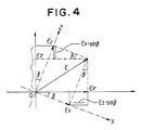
- Fig. 4 is a view for describing displacement correction computations in the displacement correcting unit 20.
- the tracer head TC is rotated by ⁇ in the B-axis direction (a direction in which rotation is performed with the Y axis as the central axis of rotation) in order to avoid interference with the model when surface tracing is performed in the XZ tracing plane (see the solid dashed lines in Fig. 4)
- this is equivalent, in relative terms, to rotating the XZ tracing plane by ⁇ while holding the tracer head fixed.
- the displacement correcting unit 20 corrects the axial displacements to ⁇ x ', ⁇ y ', ⁇ z ' by performing the computations of Eqs. (1) - (4) using the variable displacements ⁇ x , ⁇ y , ⁇ z and the rotational angles ⁇ , ⁇ in the A- and B-axis directions.
- the tracer head TC is rotated in the B-axis direction, so as not to interfere with the model MDL, when the hollow HL having the vertical wall SL [see Fig. 1(a)] is traced. More specifically, rotation conforming to a predetermined rotational angle is commanded by operating B-axis manual feed means (a manual handle or jog button) provided on the operator's panel OPP (Fig. 2).
- B-axis manual feed means a manual handle or jog button
- OPP Fig. 2
- the pulse distributor circuit PDC In response, the pulse distributor circuit PDC generates commanded pulses CP B , the number whereof corresponds to the commanded rotational angle, having a frequency conforming to the preset velocity.
- the servo-circuit SVB performs well-known velocity control to rotate the B-axis motor, thereby rotating the tracer head TC and cutter head CT in unison in the B-axis direction.
- the present position ⁇ along the B axis in position memory PM is updated in realtime. Since XZ surface tracing is performed in parallel with the foregoing B-axis rotation control, the present positions XA, ZA along the X and Z axes are also updated.
- the controller 19 (Fig. 3) of the tracer control unit TCC reads the present positions along the respective axes, performs tracer control in accordance with the predetermined tracing cycle sequence, and applies the present positions ⁇ , ⁇ along the A and B axes to the displacement correcting unit 20 at predetermined time intervals.
- the displacement correcting unit 20 performs the computations of Eqs. (1) - (4) whenever ⁇ and ⁇ are applied thereto, thereby generating the corrected axial displacements ⁇ x ′, ⁇ y ′, ⁇ z ′ conforming to the rotational angles, in the A-and B-axis directions, of the tracer head.
- the changeover circuit 15 outputs the corrected displacements conforming to the tracing plane, and the tracing direction arithmetic unit 16 computes and outputs cos ⁇ , sin ⁇ of the directions of displacement using the corrected displacements that have entered.
- the axial velocity signal generator 17 generates the axial velocities V1, V2 in the tracing control plane using the normal- and tangent-direction velocities V N , V T and the displacement directions cos ⁇ , sin ⁇ , and the distributor circuit 18 distributes the velocities V1, V2 along the axes forming the tracing plane, thereby moving the stylus 1 along the model. Processing similar to the foregoing is repeated to execute tracer control.
- the resultant displacement ⁇ is the same whether using the displacement before correction or the displacement after correction. Therefore, in Fig. 3, the resultant displacement ⁇ is computed using the displacements ⁇ x , ⁇ y , ⁇ z before correction.
- the angles of rotation are commanded manually from the operator's panel.
- a distance detector DDT is provided for optically detecting a distance L from the tracer head TC to the model MDL.
- a fluctuation in the distance exceeds a set value, this is construed as indicating an inclination and predetermined rotational angles ⁇ o , ⁇ o are commanded.
- the invention is described above for a case where rotation is performed in the two directions A and B, it can be arranged so that rotation is effected solely in the B-axis direction, by way of example.
- the arrangement would be such that a shaft SFT of a B-axis motor MTB is rotatably supported by a bearing AR, the tracer head TC and a spindle motor SPM of the cutter head CT are fixed to the shaft, and the tracer head and cutter head are rotated in unison in the direction of the arrows by rotating the B-axis motor MTB.
- a tracer head to be rotatable in a rotating direction which adopts, as an axis of rotation, an axis parallel to an axis which does not form a tracer control plane, and an angle of rotation in this rotational direction is monitored.
- Axial displacements along two axes forming the tracing plane are corrected based on the angle of rotation, and tracer control is performed using each of the axial displacements obtained by the correction.
Abstract
Description
- This invention relates to a tracer control apparatus.
- As shown in Fig. 7, tracer control usually involves detecting axial displacements εx, εy, εz, of a
stylus 1, which is in contact with a model, by means of atracer head 2, computing a resultant displacement ε (
mixing circuit 3, obtaining an error Δε between the resultant displacement ε and a reference displacement εo by anadder circuit 4, generating abnormal-direction velocity signal VN in avelocity signal generator 5 based on the characteristic Δε - VN, and generating a tangent-direction velocity signal VT in avelocity signal generator 6 based on the characteristic Δε - VT. Meanwhile, a tracing directionarithmetic circuit 7 generates cosϑ and sinϑ in a tracing direction ϑ using axial displacements ε₁, ε₂ lying in a tracer control plane and outputted by achangeover circuit 8, and an axialvelocity signal generator 9 generates axial velocities V₁, V₂ in the tracer control plane using VN, VT, cosϑ and sin ϑ, thereby moving thestylus 1 along the model at these velocities. Tracer control is executed by subsequently repeating similar processing. - In a case where a model MDL possesses a steep incline, such as a hollow HL having vertical walls, as shown in Fig. 8, the foregoing tracer control method is such that when the
stylus 1 is moved along a vertical wall portion SL, a corner portion 2a of thetracer head 2 is obstructed by the model MDL and tracing cannot be performed. - Accordingly, an object of the invention is to provide a tracer control apparatus which enables a tracer head to trace a model without impedement even if the model profile has projections and cavities of a kind that obstruct the tracer head.
- JP-A-61-79552 discloses a tracer control apparatus which is operable to effect tracer control using an optionally angled tilting tracer head, by converting a displacement signal detected by the optionally angled tilting tracer head into a displacement value for a shaft of a drive motor. Accordingly, another object of the invention is to provide a tracer control apparatus which adapts this prior disclosure to enable a model to be traced while the tracer head is rotated and arranged so as not to be obstructed by the model.
- According to the present invention there is provided a tracer control apparatus for tracing a model surface by computing feed rate components along respective axes in a tracer control plane based on a difference between a reference displacement and a resultant displacement, which is the result of combining axial displacement from a tracer head, and a tracing direction, comprising: rotating means for producing relative rotation between the tracer head and the model in a rotational direction; means for monitoring an angle of rotation in said rotational direction; means for correcting, based on said angle of rotation, axial displacements along two axes forming the tracer control plane; and means for performing tracer control using each of the axial displacements obtained by the correction; characterised in that said rotating means adopts, as an axis of rotation, an axis parallel to an axis which does not form said tracer control plane, and the tracer control apparatus comprises inclination detecting means for commanding said relative rotation of the tracer head and the model upon detecting that a change in a distance to the model surface has exceeded a set value.
- For a better understanding of the present invention and to show how it may be put into practice reference will now be made, by way of example, to the accompanying drawings in which:-
- Fig. 1 is a view for describing the general features of the present invention, in which (a) is an XZ sectional view and (b) a YZ sectional view;
- Fig. 2 is a block diagram of a tracer control system according to the invention;
- Fig. 3 is a block diagram of a tracer control unit;
- Fig. 4 is a view for describing displacement correction computations based on B-axis rotation;
- Fig. 5 is a view for describing a detection principle for detecting inclination of a model surface;
- Fig. 6 is a view for describing a tracer head rotating mechanism; and
- Figs. 7 and 8 are views for describing a problem encountered in the prior art.
- Fig. 1 is a view for describing the general features of the present invention, in which (a) is an XZ sectional view and (b) a YZ sectional view.
- ST represents a stylus, TC a tracer head, MDL a model, HL a hollow in the model, and SL, SL' vertical walls.
- It is arranged for the tracer head TC to be rotatable in a rotational direction which adopts, as an axis of rotation, an axis parallel to an axis [e.g., the Y axis in Fig. 1(a)] which does not form a tracing plane. When the hollow HL having the vertical wall SL is traced, the tracer head TC is rotated so as not to interfere with the model MDL, an angle of rotation β in the rotational direction is monitored, axial displacements εx, εz along two axes (X, Z axes) other than the axis of rotation are corrected based on the angle of rotation β, and tracer control is performed using each of the axial displacements obtained by the correction.
- Fig. 2 is a block diagram of a tracer control system according to the invention, and Fig. 3 is a block diagram of a tracer control unit.
- In Fig. 2, TRM represents a tracing machine tool, TCC a tracer control unit for executing tracer control, OPP an operator's panel for setting various data necessary for tracing, and for rotating the tracer head in an A-axis direction and a B-axis direction, PDC a pulse distributor, and SVX, SVY, SVZ, SVA, SVB servo-circuits for the respective axes.
- The servo-circuits SVX - SVZ apply a DA conversion to digitally provided velocity commands VX - VZ from the tracer control unit TCC, and control the velocity of the servomotors (not shown) of respective axes. Meanwhile, the servo-circuits SVA, SVB generate velocity commands along the A and B axes upon receiving, as inputs, command pulses CPA, CPB generated by the pulse distributor PDC and detection pulses FPA, FPB generated each time the respective A- and B-axis motors (not shown) rotate through a predetermined angle.
- PM denotes a position memory which monitors present position along each axis by up/down counting, in dependence upon the direction of rotation, detection pulses FPX - FPB generated each time the motors of the respective axes rotate a predetermined amount.
- The tracing machine tool TRM is provided with the following, not shown:
- (i) X- and Y-axis motors for driving a table TBL along the X- and Y-axis directions, respectively;
- (ii) a Z-axis motor for driving the tracer head TC and a cutter head CT in unison along the Z-axis;
- (iii) an A-axis motor for rotating the tracer head and cutter head in a direction (referred to as the A-axis direction) adopting an axis parallel to the X axis as the axis of rotation; and
- (iv) a B-axis motor for rotating the tracer head and cutter head in a direction (referred to as the B-axis direction) adopting an axis parallel to the Y axis as the axis of rotation, and pulse generators each for generating one of the detection pulses FPX, FPY, FPZ, FPA, FPB whenever the respective axial motor rotates a predetermined amount. It is permissible to adopt an arrangement in which the table TBL is rotated instead of rotating the tracer head and cutter head in the A-axis direction, with the tracer head and cutter head being rotated only in the B-axis direction.
- The model MDL and workpiece WK are secured to the table TBL, and the prescribed tracing is performed by bringing the stylus ST, which is attached to the tracer head TC, into abutting contact with the surface of the model. The cutter head CT subjects the workpiece WK to machining conforming to the shape of the model. As is well known, the tracer head TC is arranged to detect deviations εx, εy, εz in the surface of the model MDL along the respective X, Y, Z axes.
- In the profile control unit of Fig. 3, ST represents the stylus, TC the tracer head, 11 a mixing circuit, 12 an adder circuit, 13, 14 velocity signal generators for generating the normal-direction velocity signal VN and the tangent-direction velocity signal VT, respectively, 15 a changeover unit for outputting, as ε₁, ε₂, displacements forming the tracing control plane, 16 a tracing direction arithmetic unit, 17 an axial velocity signal generator for generating velocity signals V₁, V₂ in axial directions forming the tracing control plane, 18 a pulse distributor circuit for distributing the velocity signals V₁, V₂ to the servo-circuits of the respective axes as velocity commands along the axes forming the tracing plane, 19 a controller for performing overall tracer control using the data necessary for tracer control, which have been set by the operator's panel OPP (see Fig. 2) and the present positions XA - β along the respective axes, and 20 a displacement correcting unit for correcting the axial displacements εx, εy, εz based on the rotational angles α, β in the A-axis and B-axis directions.
- Fig. 4 is a view for describing displacement correction computations in the
displacement correcting unit 20. For example, if the tracer head TC is rotated by β in the B-axis direction (a direction in which rotation is performed with the Y axis as the central axis of rotation) in order to avoid interference with the model when surface tracing is performed in the XZ tracing plane (see the solid dashed lines in Fig. 4), this is equivalent, in relative terms, to rotating the XZ tracing plane by β while holding the tracer head fixed. From Fig. 4, the axial displacements εx', εz' following rotation are as indicated by the following equations, using the axial displacements εx, εz prior to rotation and the rotational angle β:

displacement correcting unit 20 corrects the axial displacements to εx', εy', εz' by performing the computations of Eqs. (1) - (4) using the variable displacements εx, εy, εz and the rotational angles α, β in the A- and B-axis directions. - The overall operation of the described and illustrated embodiment will now be described in accordance with Figs. 1 through 3.
- By way of example, if surface tracing is performed in the XZ tracing plane, the tracer head TC is rotated in the B-axis direction, so as not to interfere with the model MDL, when the hollow HL having the vertical wall SL [see Fig. 1(a)] is traced. More specifically, rotation conforming to a predetermined rotational angle is commanded by operating B-axis manual feed means (a manual handle or jog button) provided on the operator's panel OPP (Fig. 2). An arrangement can be adopted in which the rotational angle is preset to a fixed value.
- In response, the pulse distributor circuit PDC generates commanded pulses CPB, the number whereof corresponds to the commanded rotational angle, having a frequency conforming to the preset velocity. As a result, the servo-circuit SVB performs well-known velocity control to rotate the B-axis motor, thereby rotating the tracer head TC and cutter head CT in unison in the B-axis direction.
- When the detection pulse FPB is generated by rotation of the B-axis motor, the present position β along the B axis in position memory PM is updated in realtime. Since XZ surface tracing is performed in parallel with the foregoing B-axis rotation control, the present positions XA, ZA along the X and Z axes are also updated.
- The controller 19 (Fig. 3) of the tracer control unit TCC reads the present positions along the respective axes, performs tracer control in accordance with the predetermined tracing cycle sequence, and applies the present positions α, β along the A and B axes to the
displacement correcting unit 20 at predetermined time intervals. - The
displacement correcting unit 20 performs the computations of Eqs. (1) - (4) whenever α and β are applied thereto, thereby generating the corrected axial displacements εx′, εy′, εz′ conforming to the rotational angles, in the A-and B-axis directions, of the tracer head. Thechangeover circuit 15 outputs the corrected displacements conforming to the tracing plane, and the tracing directionarithmetic unit 16 computes and outputs cosϑ, sinϑ of the directions of displacement using the corrected displacements that have entered. The axialvelocity signal generator 17 generates the axial velocities V₁, V₂ in the tracing control plane using the normal- and tangent-direction velocities VN, VT and the displacement directions cosϑ, sinϑ, and thedistributor circuit 18 distributes the velocities V₁, V₂ along the axes forming the tracing plane, thereby moving thestylus 1 along the model. Processing similar to the foregoing is repeated to execute tracer control. - As will be evident from Fig. 4, the resultant displacement ε is the same whether using the displacement before correction or the displacement after correction. Therefore, in Fig. 3, the resultant displacement ε is computed using the displacements εx, εy, εz before correction.
- In the foregoing, the angles of rotation are commanded manually from the operator's panel. However, as shown in Fig. 5, an arrangement is adopted in accordance with the invention in which a distance detector DDT is provided for optically detecting a distance L from the tracer head TC to the model MDL. When a fluctuation in the distance exceeds a set value, this is construed as indicating an inclination and predetermined rotational angles αo, βo are commanded.
- Further, though the invention is described above for a case where rotation is performed in the two directions A and B, it can be arranged so that rotation is effected solely in the B-axis direction, by way of example. In this case, as shown in Fig. 6, the arrangement would be such that a shaft SFT of a B-axis motor MTB is rotatably supported by a bearing AR, the tracer head TC and a spindle motor SPM of the cutter head CT are fixed to the shaft, and the tracer head and cutter head are rotated in unison in the direction of the arrows by rotating the B-axis motor MTB.
- Thus, in accordance with the present invention, it is arranged for a tracer head to be rotatable in a rotating direction which adopts, as an axis of rotation, an axis parallel to an axis which does not form a tracer control plane, and an angle of rotation in this rotational direction is monitored. Axial displacements along two axes forming the tracing plane are corrected based on the angle of rotation, and tracer control is performed using each of the axial displacements obtained by the correction. As a result, tracing can be performed without the tracer head interfering with the model even if the model has sharply inclined projections or cavities.
Claims (4)
- A tracer control apparatus for tracing a model (MDL) surface by computing feed rate components along respective axes (eg X, Z) in a tracer control plane based on a difference (Δε) between a reference displacement (εo) and a resultant displacement (ε), which is the result of combining axial displacements (εx, εy, εz) from a tracer head (TC), and a tracing direction, comprising:
rotating means (MTB) for producing relative rotation between the tracer head (TC) and the model (MDL) in a rotational direction;
means for monitoring an angle of rotation (eg β) in said rotational direction;
means (20) for correcting, based on said angle of rotation (eg β), axial displacements (eg εx, εz) along two axes (eg X, Z) forming the tracer control plane; and
means for performing tracer control using each of the axial displacements (eg εx, εz) obtained by the correction;
characterised in that said rotating means (MTB) adopts, as an axis of rotation, an axis parallel to an axis (eg Y) which does not form said tracer control plane, and the tracer control apparatus comprises inclination detecting means (DDT) for commanding said relative rotation of the tracer head (TC) and the model (MDL) upon detecting that a change in a distance to the model (MDL) surface has exceeded a set value. - A tracer control apparatus according to claim 1, characterised in that said displacement correcting means (20) computes corrected displacements εx', εz' along respective axes in accordance with the following equations:

- A tracer control apparatus according to claim 1 or 2, characterised by having an operator's panel operable to command said relative rotation of the tracer head (TC) and the model (MDL).
- A tracer control apparatus according to any one of the preceding claims, wherein said rotating means (MTB) produces rotation of the tracer head (TC).
Applications Claiming Priority (3)
| Application Number | Priority Date | Filing Date | Title |
|---|---|---|---|
| JP62274801A JPH01115549A (en) | 1987-10-30 | 1987-10-30 | Copying controlling system |
| JP274801/87 | 1987-10-30 | ||
| PCT/JP1988/001085 WO1989004237A1 (en) | 1987-10-30 | 1988-10-26 | Profile controller |
Publications (3)
| Publication Number | Publication Date |
|---|---|
| EP0347466A1 EP0347466A1 (en) | 1989-12-27 |
| EP0347466A4 EP0347466A4 (en) | 1993-06-09 |
| EP0347466B1 true EP0347466B1 (en) | 1995-11-02 |
Family
ID=17546753
Family Applications (1)
| Application Number | Title | Priority Date | Filing Date |
|---|---|---|---|
| EP88909362A Expired - Lifetime EP0347466B1 (en) | 1987-10-30 | 1988-10-26 | Profile controller |
Country Status (5)
| Country | Link |
|---|---|
| US (1) | US4982336A (en) |
| EP (1) | EP0347466B1 (en) |
| JP (1) | JPH01115549A (en) |
| DE (1) | DE3854648T2 (en) |
| WO (1) | WO1989004237A1 (en) |
Families Citing this family (1)
| Publication number | Priority date | Publication date | Assignee | Title |
|---|---|---|---|---|
| JPH03184749A (en) * | 1989-12-11 | 1991-08-12 | Fanuc Ltd | Profile controller for rotator |
Family Cites Families (6)
| Publication number | Priority date | Publication date | Assignee | Title |
|---|---|---|---|---|
| JPS599305B2 (en) * | 1978-03-23 | 1984-03-01 | ファナック株式会社 | Copying control device |
| JPS6010862B2 (en) * | 1980-06-03 | 1985-03-20 | ファナック株式会社 | 3D scanning control method |
| JPS59161252A (en) * | 1983-03-04 | 1984-09-12 | Fanuc Ltd | Profiling control device |
| JPS6179552A (en) * | 1984-09-28 | 1986-04-23 | Mitsubishi Heavy Ind Ltd | Tracer controller |
| JPH074739B2 (en) * | 1985-07-01 | 1995-01-25 | フアナツク株式会社 | Digitizing method |
| JP2559660B2 (en) * | 1992-12-11 | 1996-12-04 | 永井鉄工株式会社 | Tail sealing method for web roll |
-
1987
- 1987-10-30 JP JP62274801A patent/JPH01115549A/en active Pending
-
1988
- 1988-10-26 WO PCT/JP1988/001085 patent/WO1989004237A1/en active IP Right Grant
- 1988-10-26 EP EP88909362A patent/EP0347466B1/en not_active Expired - Lifetime
- 1988-10-26 DE DE3854648T patent/DE3854648T2/en not_active Expired - Fee Related
- 1988-10-26 US US07/368,321 patent/US4982336A/en not_active Expired - Fee Related
Also Published As
| Publication number | Publication date |
|---|---|
| DE3854648D1 (en) | 1995-12-07 |
| WO1989004237A1 (en) | 1989-05-18 |
| JPH01115549A (en) | 1989-05-08 |
| EP0347466A1 (en) | 1989-12-27 |
| EP0347466A4 (en) | 1993-06-09 |
| DE3854648T2 (en) | 1996-03-21 |
| US4982336A (en) | 1991-01-01 |
Similar Documents
| Publication | Publication Date | Title |
|---|---|---|
| EP0374139B1 (en) | Multi-axis bevel and hypoid gear generating machine | |
| EP0158447B1 (en) | System for controlling a robot in association with a rotary table | |
| US20030040258A1 (en) | Machine and method for producing bevel gears | |
| EP0079965B1 (en) | A numerically controlled gear machining device | |
| US5194790A (en) | Control device for controlling a servo motor | |
| US4588872A (en) | Self-guided welding machine | |
| US6427098B1 (en) | Method for controlling pivoting machine member | |
| EP0323517B1 (en) | Profiling method | |
| KR100310814B1 (en) | Method and apparatus for processing scrolled workpiece | |
| US4639172A (en) | Trace control method | |
| US4375670A (en) | Machine tool for machining crankshafts and control system for the machine tool | |
| EP0347466B1 (en) | Profile controller | |
| EP0364593B1 (en) | Machine tool having two main spindles | |
| EP0015650B1 (en) | Tracer control apparatus | |
| US4575665A (en) | Tracer control method | |
| JPH0132011B2 (en) | ||
| JPH0651241B2 (en) | Y-axis processing method | |
| EP0386251A1 (en) | Profile control method | |
| EP0709157B1 (en) | Multi-axis bevel and hypoid gear generating machine | |
| JPH04331048A (en) | Tracer controller | |
| EP0190357B1 (en) | Apparatus for controlling profiling in any direction | |
| JPH05216516A (en) | Laser beam machine | |
| KR930006786B1 (en) | Controller for machine tool | |
| JP2000158260A (en) | Table for machine tool | |
| JP2959597B2 (en) | Numerical control device with cam groove machining control function |
Legal Events
| Date | Code | Title | Description |
|---|---|---|---|
| PUAI | Public reference made under article 153(3) epc to a published international application that has entered the european phase |
Free format text: ORIGINAL CODE: 0009012 |
|
| 17P | Request for examination filed |
Effective date: 19890710 |
|
| AK | Designated contracting states |
Kind code of ref document: A1 Designated state(s): DE FR GB IT |
|
| A4 | Supplementary search report drawn up and despatched |
Effective date: 19930420 |
|
| AK | Designated contracting states |
Kind code of ref document: A4 Designated state(s): DE FR GB IT |
|
| 17Q | First examination report despatched |
Effective date: 19940218 |
|
| GRAA | (expected) grant |
Free format text: ORIGINAL CODE: 0009210 |
|
| AK | Designated contracting states |
Kind code of ref document: B1 Designated state(s): DE FR GB IT |
|
| PG25 | Lapsed in a contracting state [announced via postgrant information from national office to epo] |
Ref country code: FR Effective date: 19951102 |
|
| REF | Corresponds to: |
Ref document number: 3854648 Country of ref document: DE Date of ref document: 19951207 |
|
| ITF | It: translation for a ep patent filed |
Owner name: ING. ZINI MARANESI & C. S.R.L. |
|
| EN | Fr: translation not filed | ||
| PLBE | No opposition filed within time limit |
Free format text: ORIGINAL CODE: 0009261 |
|
| STAA | Information on the status of an ep patent application or granted ep patent |
Free format text: STATUS: NO OPPOSITION FILED WITHIN TIME LIMIT |
|
| 26N | No opposition filed | ||
| PG25 | Lapsed in a contracting state [announced via postgrant information from national office to epo] |
Ref country code: GB Effective date: 19961026 |
|
| GBPC | Gb: european patent ceased through non-payment of renewal fee |
Effective date: 19961026 |
|
| PG25 | Lapsed in a contracting state [announced via postgrant information from national office to epo] |
Ref country code: DE Effective date: 19970701 |
|
| PG25 | Lapsed in a contracting state [announced via postgrant information from national office to epo] |
Ref country code: IT Free format text: LAPSE BECAUSE OF NON-PAYMENT OF DUE FEES Effective date: 20051026 |