EP0176539B1 - Détecteur de vitesse de rotation - Google Patents
Détecteur de vitesse de rotation Download PDFInfo
- Publication number
- EP0176539B1 EP0176539B1 EP85901506A EP85901506A EP0176539B1 EP 0176539 B1 EP0176539 B1 EP 0176539B1 EP 85901506 A EP85901506 A EP 85901506A EP 85901506 A EP85901506 A EP 85901506A EP 0176539 B1 EP0176539 B1 EP 0176539B1
- Authority
- EP
- European Patent Office
- Prior art keywords
- assembly
- axis
- sheets
- piezoelectric member
- electrical output
- Prior art date
- Legal status (The legal status is an assumption and is not a legal conclusion. Google has not performed a legal analysis and makes no representation as to the accuracy of the status listed.)
- Expired
Links
Images

Classifications
-
- G—PHYSICS
- G01—MEASURING; TESTING
- G01C—MEASURING DISTANCES, LEVELS OR BEARINGS; SURVEYING; NAVIGATION; GYROSCOPIC INSTRUMENTS; PHOTOGRAMMETRY OR VIDEOGRAMMETRY
- G01C19/00—Gyroscopes; Turn-sensitive devices using vibrating masses; Turn-sensitive devices without moving masses; Measuring angular rate using gyroscopic effects
- G01C19/56—Turn-sensitive devices using vibrating masses, e.g. vibratory angular rate sensors based on Coriolis forces
-
- Y—GENERAL TAGGING OF NEW TECHNOLOGICAL DEVELOPMENTS; GENERAL TAGGING OF CROSS-SECTIONAL TECHNOLOGIES SPANNING OVER SEVERAL SECTIONS OF THE IPC; TECHNICAL SUBJECTS COVERED BY FORMER USPC CROSS-REFERENCE ART COLLECTIONS [XRACs] AND DIGESTS
- Y10—TECHNICAL SUBJECTS COVERED BY FORMER USPC
- Y10S—TECHNICAL SUBJECTS COVERED BY FORMER USPC CROSS-REFERENCE ART COLLECTIONS [XRACs] AND DIGESTS
- Y10S310/00—Electrical generator or motor structure
- Y10S310/80—Piezoelectric polymers, e.g. PVDF
-
- Y—GENERAL TAGGING OF NEW TECHNOLOGICAL DEVELOPMENTS; GENERAL TAGGING OF CROSS-SECTIONAL TECHNOLOGIES SPANNING OVER SEVERAL SECTIONS OF THE IPC; TECHNICAL SUBJECTS COVERED BY FORMER USPC CROSS-REFERENCE ART COLLECTIONS [XRACs] AND DIGESTS
- Y10—TECHNICAL SUBJECTS COVERED BY FORMER USPC
- Y10S—TECHNICAL SUBJECTS COVERED BY FORMER USPC CROSS-REFERENCE ART COLLECTIONS [XRACs] AND DIGESTS
- Y10S73/00—Measuring and testing
- Y10S73/04—Piezoelectric
Definitions
- This invention relates to a device for sensing rate of rotation, and to apparatus incorporating such devices.
- An object of the present invention is to provide a simple and inexpensive rate sensor which has . sufficient accuracy for certain applications.
- FR-A-1 202 614 discloses a number of piezoelectric bimorph devices, one of which ( Figure 9) provides a rotation rate sensor. This uses a pair of piezoelectric crystals secured together. One crystal is driven by an oscillator to cause the bimorph to vibrate, and thus generate an electrical output from the other crystal, which output alters as the bimorph twists when driven in rotation.
- the present invention which is characterised as defined in claim 1, improves on this prior art by providing a much greater degree of sensitivity.
- US-A-3 233 466 describes a piezoelectric accelerometer making use of a pair of piezoelectric crystals oscillating in flexure, with the frequency of oscillation acting as a measure of acceleration forces.
- US-A-3 304 787 shows a solid-state accelerometer device utilising a triad of mutually orthogonal piezoresistive elements mounted in cantilever fashion, the resistance of these elements being changed by acceleration forces and measured in a bridge circuit.
- EP-Al-0 021 898 discloses the use of polymeric piezoelectric films in an acceleration sensor.
- the devices shown in this document are based on arranging a film of this nature to be deformed by acceleration, and measuring the electrical output directly produced by such deformation.
- the polymeric piezoelectric material used in the device of the present invention is preferably polyvinylidene fluoride (PVDF).
- KYNAR Trade Mark
- the invention provides apparatus including a plurality of devices as defined above arranged with their said longitudinal axes mutually perpendicular, whereby movement of the apparatus in a two-dimensional plane or in three-dimensional space may be measured.
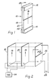
- the device comprises a sheet laminate 10 clamped at its top and bottom edges by parts 12, 14 of a rigid housing (the remainder of which is not shown) such that in its rest position the laminate 10 lies in a reference plane having a longitudinal axis designated at 16.
- the laminate 10 consists of three sheets 18, 20, 22 bonded together. Each of these sheets is of polarised PVDF film.
- the first and second sheets 18 and 20 have the main uniaxial mode 19 of the film aligned with the axis 16, while the third sheet 22 has its main uniaxial mode 23 at right angles to the axis 16.
- the three sheets 18, 20, 22 are bonded together by any suitable insulating adhesive.
- the first and second sheets 18 and 20 are oppositely connected to an oscillator 24.
- the applied electric signal thus causes one sheet to lengthen while the other contracts and vice versa, and the laminate oscillates transverse to the axis 16.
- the oscillator 24 suitably oscillates at the resonant frequency of the mechanical system.
- the third sheet 22 experiences stress in a direction normal to its main uniaxial mode, and the voltage induced therein is small (a few millivolts).
- the oscillating laminate has an inertia which tends to resist movement out of its initial position; this results in twisting of the laminate 10, the top and bottom edges moving with the housing but the central area lagging.
- some other planar oscillating element could be used, such as a metal plate driven by a ceramic transducer.
- the device described may be modified to give an output signal which is a function of linear acceleration. This requires linear acceleration to produce twisting of the laminate while isolating the laminate from rotational movement. This may be accomplished as shown in Figure 3 by rotatably mounting the laminate 10 within an outer body 30 on bearings 32, and mounting a mass 34 on the laminate eccentric to the rotation axis 36.
- the resulting output signals representing rotation and/or linear acceleration can be processed to define movement of the platform in a 2-dimensional plane or in 3-dimensional space.
- the device of the present invention would allow bias stability of about 1°/ minute to be achieved. This is not sufficiently accurate for applications such as navigation. It is envisaged, however, that it will be suitable for small-scale applications such as the positioning of movable machinery especially where the part in question is returned periodically (in a time scale of a few minutes) to a fixed datum position.
Landscapes
- Physics & Mathematics (AREA)
- Engineering & Computer Science (AREA)
- General Physics & Mathematics (AREA)
- Radar, Positioning & Navigation (AREA)
- Remote Sensing (AREA)
- Gyroscopes (AREA)
- General Electrical Machinery Utilizing Piezoelectricity, Electrostriction Or Magnetostriction (AREA)
Abstract
Claims (5)
Priority Applications (1)
| Application Number | Priority Date | Filing Date | Title |
|---|---|---|---|
| AT85901506T ATE36916T1 (de) | 1984-04-04 | 1985-04-01 | Rotationsgeschwindigkeitsaufnehmer. |
Applications Claiming Priority (2)
| Application Number | Priority Date | Filing Date | Title |
|---|---|---|---|
| GB8408659 | 1984-04-04 | ||
| GB848408659A GB8408659D0 (en) | 1984-04-04 | 1984-04-04 | Rotation rate sensor |
Publications (2)
| Publication Number | Publication Date |
|---|---|
| EP0176539A1 EP0176539A1 (fr) | 1986-04-09 |
| EP0176539B1 true EP0176539B1 (fr) | 1988-08-31 |
Family
ID=10559149
Family Applications (1)
| Application Number | Title | Priority Date | Filing Date |
|---|---|---|---|
| EP85901506A Expired EP0176539B1 (fr) | 1984-04-04 | 1985-04-01 | Détecteur de vitesse de rotation |
Country Status (5)
| Country | Link |
|---|---|
| US (1) | US4689992A (fr) |
| EP (1) | EP0176539B1 (fr) |
| DE (1) | DE3564741D1 (fr) |
| GB (1) | GB8408659D0 (fr) |
| WO (1) | WO1985004722A1 (fr) |
Families Citing this family (19)
| Publication number | Priority date | Publication date | Assignee | Title |
|---|---|---|---|---|
| EP0262637B1 (fr) * | 1986-09-29 | 1995-03-22 | Mitsubishi Chemical Corporation | Dispositif d'actionnement piézoélectrique |
| US5166571A (en) * | 1987-08-28 | 1992-11-24 | Nec Home Electronics, Ltd. | Vibration gyro having an H-shaped vibrator |
| US4868447A (en) * | 1987-09-11 | 1989-09-19 | Cornell Research Foundation, Inc. | Piezoelectric polymer laminates for torsional and bending modal control |
| US4792715A (en) * | 1987-11-16 | 1988-12-20 | Barsky Michael F | Robot gripper control system using PVDF piezoelectric sensors |
| DE3943805C2 (de) * | 1988-08-12 | 2000-01-05 | Murata Manufacturing Co | Schwingkreisel |
| DE3926504C2 (de) * | 1988-08-12 | 1999-11-18 | Murata Manufacturing Co | Schwingkreisel |
| US5874674A (en) * | 1988-08-12 | 1999-02-23 | Murata Manufacturing Co., Ltd. | Vibrator including piezoelectric electrodes or detectors arranged to be non-parallel and non-perpendicular to coriolis force direction and vibratory gyroscope using the same |
| US5049776A (en) * | 1988-11-09 | 1991-09-17 | Aisin Seiki Kabushiki Kaisha | Apparatus for detecting rotation |
| GB9018661D0 (en) * | 1990-08-24 | 1990-10-10 | British Aerospace | Multipole vibrating surface gyroscope |
| EP0572657B1 (fr) * | 1991-12-23 | 1998-08-05 | Elf Atochem North America, Inc. | Accelerometre multimode |
| DE69414739T2 (de) * | 1993-03-19 | 1999-07-01 | Murata Mfg. Co., Ltd., Nagaokakyo, Kyoto | Beschleunigungsmessaufnehmer |
| US5802684A (en) * | 1993-09-14 | 1998-09-08 | Nikon Corporation | Process for producing a vibration angular-velocity sensor |
| DE4336004C2 (de) * | 1993-10-21 | 1998-05-28 | Siemens Ag | Schwingungsgyroskop |
| JP2780643B2 (ja) * | 1994-06-03 | 1998-07-30 | 株式会社村田製作所 | 振動ジャイロ |
| DE19522543A1 (de) * | 1994-08-01 | 1996-02-08 | Ntn Toyo Bearing Co Ltd | Piezoelektrisches Film-Meßfühlersystem für Lager |
| DE19528961C2 (de) | 1995-08-08 | 1998-10-29 | Daimler Benz Ag | Mikromechanischer Drehratensensor (DRS) und Sensoranordnung |
| GB2450157B (en) * | 2007-06-15 | 2011-12-21 | Baker Hughes Inc | System for determining an initial direction of rotation of an electrical submersible pump |
| JP2009198493A (ja) * | 2007-12-26 | 2009-09-03 | Rohm Co Ltd | 角速度検出装置 |
| DE102009030693A1 (de) * | 2009-06-26 | 2010-12-30 | Fraunhofer-Gesellschaft zur Förderung der angewandten Forschung e.V. | Elektroaktiver Elastomeraktor sowie Verfahren zu dessen Herstellung |
Family Cites Families (11)
| Publication number | Priority date | Publication date | Assignee | Title |
|---|---|---|---|---|
| US3219850A (en) * | 1957-09-16 | 1965-11-23 | Clevite Corp | Electromechanical transducers |
| FR1202614A (fr) * | 1958-09-30 | 1960-01-12 | Clevite Corp | Transducteur électromécanique |
| US3304787A (en) * | 1962-12-29 | 1967-02-21 | Toyoda Chuo Kenkyusho Kk | Three-dimensional accelerometer device |
| US3233466A (en) * | 1963-06-24 | 1966-02-08 | Bendix Corp | Piezoelectric accelerometer |
| US3520195A (en) * | 1965-10-11 | 1970-07-14 | Gen Electric | Solid state angular velocity sensing device |
| JPS4975182A (fr) * | 1972-11-20 | 1974-07-19 | ||
| US3971250A (en) * | 1975-02-18 | 1976-07-27 | Minnesota Mining And Manufacturing Company | Electret sensing medium having plural sensing units |
| FR2460485A1 (fr) * | 1979-06-29 | 1981-01-23 | Thomson Csf | Capteur d'acceleration piezo-electrique a element transducteur en materiau polymere et systeme de securite pour centrifugeuse comportant un tel capteur |
| US4431935A (en) * | 1981-09-15 | 1984-02-14 | Rockwell International Corporation | Sensor structure incorporating multiple piezoelectric generators |
| FR2517823B1 (fr) * | 1981-12-08 | 1986-10-10 | Nat Res Dev | Gyroscope oscillant |
| GB2117115B (en) * | 1982-03-23 | 1985-11-06 | Standard Telephones Cables Ltd | Surface acoustic wave accelerometer |
-
1984
- 1984-04-04 GB GB848408659A patent/GB8408659D0/en active Pending
-
1985
- 1985-04-01 DE DE8585901506T patent/DE3564741D1/de not_active Expired
- 1985-04-01 US US06/809,889 patent/US4689992A/en not_active Expired - Fee Related
- 1985-04-01 EP EP85901506A patent/EP0176539B1/fr not_active Expired
- 1985-04-01 WO PCT/GB1985/000131 patent/WO1985004722A1/fr active IP Right Grant
Also Published As
| Publication number | Publication date |
|---|---|
| GB8408659D0 (en) | 1984-05-16 |
| US4689992A (en) | 1987-09-01 |
| EP0176539A1 (fr) | 1986-04-09 |
| WO1985004722A1 (fr) | 1985-10-24 |
| DE3564741D1 (en) | 1988-10-06 |
Similar Documents
| Publication | Publication Date | Title |
|---|---|---|
| EP0176539B1 (fr) | Détecteur de vitesse de rotation | |
| US4654663A (en) | Angular rate sensor system | |
| EP0636870B1 (fr) | Capteur de force à éléments piézoélectriques | |
| CN100538272C (zh) | 压电陀螺元件和压电陀螺仪 | |
| JP3151927B2 (ja) | 加速度センサ | |
| US5430342A (en) | Single bar type vibrating element angular rate sensor system | |
| EP0685704B1 (fr) | Gyroscope à vibration | |
| GB2158579A (en) | Angular rate sensor system | |
| CA2116572C (fr) | Capteur de rotation | |
| JP3039860B2 (ja) | モノリシック振動ビーム角速度センサ | |
| JPH0894661A (ja) | 圧電素子を用いた加速度・角速度センサ | |
| JP5025965B2 (ja) | 慣性センサ素子 | |
| JP2000512019A (ja) | 小型ボックス型振動ジャイロスコープ | |
| EP0038348A1 (fr) | Detecteur de nombre de tours vibratoire piezoelectrique equilibre par une force | |
| EP0664003B1 (fr) | Detecteur de rotation par onde de propagation dans un film ferroelectrique fin | |
| JPS5897610A (ja) | 捩り−周波数変換器 | |
| KR100442823B1 (ko) | 마이크로자이로스코프 | |
| JP3136544B2 (ja) | ジャイロ装置 | |
| JP3139211B2 (ja) | 加速度センサ | |
| JP3371608B2 (ja) | 振動ジャイロ | |
| JPS6246266A (ja) | 振動センサ | |
| KR960010421B1 (ko) | 압전회전각센서 | |
| JPS6342417A (ja) | 圧電体角速度センサ− | |
| JPH06308149A (ja) | 加速度センサ | |
| JP2011069728A (ja) | 多軸加速度センサー、多軸加速度検出方法 |
Legal Events
| Date | Code | Title | Description |
|---|---|---|---|
| PUAI | Public reference made under article 153(3) epc to a published international application that has entered the european phase |
Free format text: ORIGINAL CODE: 0009012 |
|
| AK | Designated contracting states |
Kind code of ref document: A1 Designated state(s): AT BE CH DE FR GB IT LI LU NL SE |
|
| 17P | Request for examination filed |
Effective date: 19860416 |
|
| 17Q | First examination report despatched |
Effective date: 19871001 |
|
| GRAA | (expected) grant |
Free format text: ORIGINAL CODE: 0009210 |
|
| RAP1 | Party data changed (applicant data changed or rights of an application transferred) |
Owner name: SYRINX INNOVATIONS LIMITED |
|
| AK | Designated contracting states |
Kind code of ref document: B1 Designated state(s): AT BE CH DE FR GB IT LI LU NL SE |
|
| PG25 | Lapsed in a contracting state [announced via postgrant information from national office to epo] |
Ref country code: IT Free format text: LAPSE BECAUSE OF FAILURE TO SUBMIT A TRANSLATION OF THE DESCRIPTION OR TO PAY THE FEE WITHIN THE PRESCRIBED TIME-LIMIT;WARNING: LAPSES OF ITALIAN PATENTS WITH EFFECTIVE DATE BEFORE 2007 MAY HAVE OCCURRED AT ANY TIME BEFORE 2007. THE CORRECT EFFECTIVE DATE MAY BE DIFFERENT FROM THE ONE RECORDED. Effective date: 19880831 Ref country code: AT Effective date: 19880831 Ref country code: SE Effective date: 19880831 Ref country code: NL Effective date: 19880831 |
|
| REF | Corresponds to: |
Ref document number: 36916 Country of ref document: AT Date of ref document: 19880915 Kind code of ref document: T |
|
| REF | Corresponds to: |
Ref document number: 3564741 Country of ref document: DE Date of ref document: 19881006 |
|
| REG | Reference to a national code |
Ref country code: CH Ref legal event code: PFA Free format text: PENNWALT PIEZO FILM LIMITED |
|
| ET | Fr: translation filed | ||
| RAP2 | Party data changed (patent owner data changed or rights of a patent transferred) |
Owner name: PENNWALT PIEZO FILM LIMITED |
|
| NLV1 | Nl: lapsed or annulled due to failure to fulfill the requirements of art. 29p and 29m of the patents act | ||
| PG25 | Lapsed in a contracting state [announced via postgrant information from national office to epo] |
Ref country code: GB Effective date: 19890401 |
|
| PG25 | Lapsed in a contracting state [announced via postgrant information from national office to epo] |
Ref country code: LI Effective date: 19890430 Ref country code: LU Free format text: LAPSE BECAUSE OF NON-PAYMENT OF DUE FEES Effective date: 19890430 Ref country code: CH Effective date: 19890430 Ref country code: BE Effective date: 19890430 |
|
| PLBE | No opposition filed within time limit |
Free format text: ORIGINAL CODE: 0009261 |
|
| STAA | Information on the status of an ep patent application or granted ep patent |
Free format text: STATUS: NO OPPOSITION FILED WITHIN TIME LIMIT |
|
| 26N | No opposition filed | ||
| BERE | Be: lapsed |
Owner name: PENNWALT PIEZO FILM LTD Effective date: 19890430 |
|
| GBPC | Gb: european patent ceased through non-payment of renewal fee | ||
| PG25 | Lapsed in a contracting state [announced via postgrant information from national office to epo] |
Ref country code: FR Free format text: LAPSE BECAUSE OF NON-PAYMENT OF DUE FEES Effective date: 19891228 |
|
| REG | Reference to a national code |
Ref country code: CH Ref legal event code: PL |
|
| BECN | Be: change of holder's name |
Effective date: 19880831 |
|
| PG25 | Lapsed in a contracting state [announced via postgrant information from national office to epo] |
Ref country code: DE Effective date: 19900103 |
|
| REG | Reference to a national code |
Ref country code: FR Ref legal event code: ST |