EP0176324B1 - Gerät zur Synchronisierung verschiedener Fernsehsysteme - Google Patents
Gerät zur Synchronisierung verschiedener Fernsehsysteme Download PDFInfo
- Publication number
- EP0176324B1 EP0176324B1 EP19850306688 EP85306688A EP0176324B1 EP 0176324 B1 EP0176324 B1 EP 0176324B1 EP 19850306688 EP19850306688 EP 19850306688 EP 85306688 A EP85306688 A EP 85306688A EP 0176324 B1 EP0176324 B1 EP 0176324B1
- Authority
- EP
- European Patent Office
- Prior art keywords
- time code
- signal
- synchronizing
- synchronizing signal
- digital audio
- Prior art date
- Legal status (The legal status is an assumption and is not a legal conclusion. Google has not performed a legal analysis and makes no representation as to the accuracy of the status listed.)
- Expired - Lifetime
Links
Images


Classifications
-
- G—PHYSICS
- G11—INFORMATION STORAGE
- G11B—INFORMATION STORAGE BASED ON RELATIVE MOVEMENT BETWEEN RECORD CARRIER AND TRANSDUCER
- G11B27/00—Editing; Indexing; Addressing; Timing or synchronising; Monitoring; Measuring tape travel
- G11B27/10—Indexing; Addressing; Timing or synchronising; Measuring tape travel
- G11B27/19—Indexing; Addressing; Timing or synchronising; Measuring tape travel by using information detectable on the record carrier
- G11B27/28—Indexing; Addressing; Timing or synchronising; Measuring tape travel by using information detectable on the record carrier by using information signals recorded by the same method as the main recording
- G11B27/32—Indexing; Addressing; Timing or synchronising; Measuring tape travel by using information detectable on the record carrier by using information signals recorded by the same method as the main recording on separate auxiliary tracks of the same or an auxiliary record carrier
- G11B27/322—Indexing; Addressing; Timing or synchronising; Measuring tape travel by using information detectable on the record carrier by using information signals recorded by the same method as the main recording on separate auxiliary tracks of the same or an auxiliary record carrier used signal is digitally coded
- G11B27/323—Time code signal, e.g. on a cue track as SMPTE- or EBU-time code
-
- G—PHYSICS
- G11—INFORMATION STORAGE
- G11B—INFORMATION STORAGE BASED ON RELATIVE MOVEMENT BETWEEN RECORD CARRIER AND TRANSDUCER
- G11B27/00—Editing; Indexing; Addressing; Timing or synchronising; Monitoring; Measuring tape travel
- G11B27/02—Editing, e.g. varying the order of information signals recorded on, or reproduced from, record carriers
- G11B27/022—Electronic editing of analogue information signals, e.g. audio or video signals
- G11B27/028—Electronic editing of analogue information signals, e.g. audio or video signals with computer assistance
-
- G—PHYSICS
- G11—INFORMATION STORAGE
- G11B—INFORMATION STORAGE BASED ON RELATIVE MOVEMENT BETWEEN RECORD CARRIER AND TRANSDUCER
- G11B27/00—Editing; Indexing; Addressing; Timing or synchronising; Monitoring; Measuring tape travel
- G11B27/10—Indexing; Addressing; Timing or synchronising; Measuring tape travel
- G11B27/19—Indexing; Addressing; Timing or synchronising; Measuring tape travel by using information detectable on the record carrier
- G11B27/28—Indexing; Addressing; Timing or synchronising; Measuring tape travel by using information detectable on the record carrier by using information signals recorded by the same method as the main recording
-
- G—PHYSICS
- G11—INFORMATION STORAGE
- G11B—INFORMATION STORAGE BASED ON RELATIVE MOVEMENT BETWEEN RECORD CARRIER AND TRANSDUCER
- G11B2220/00—Record carriers by type
- G11B2220/20—Disc-shaped record carriers
- G11B2220/25—Disc-shaped record carriers characterised in that the disc is based on a specific recording technology
- G11B2220/2537—Optical discs
- G11B2220/2545—CDs
-
- G—PHYSICS
- G11—INFORMATION STORAGE
- G11B—INFORMATION STORAGE BASED ON RELATIVE MOVEMENT BETWEEN RECORD CARRIER AND TRANSDUCER
- G11B2220/00—Record carriers by type
- G11B2220/90—Tape-like record carriers
-
- G—PHYSICS
- G11—INFORMATION STORAGE
- G11B—INFORMATION STORAGE BASED ON RELATIVE MOVEMENT BETWEEN RECORD CARRIER AND TRANSDUCER
- G11B2220/00—Record carriers by type
- G11B2220/90—Tape-like record carriers
- G11B2220/91—Helical scan format, wherein tracks are slightly tilted with respect to tape direction, e.g. VHS, DAT, DVC, AIT or exabyte
- G11B2220/913—Digital audio tape [DAT] format
-
- G—PHYSICS
- G11—INFORMATION STORAGE
- G11B—INFORMATION STORAGE BASED ON RELATIVE MOVEMENT BETWEEN RECORD CARRIER AND TRANSDUCER
- G11B27/00—Editing; Indexing; Addressing; Timing or synchronising; Monitoring; Measuring tape travel
- G11B27/002—Programmed access in sequence to a plurality of record carriers or indexed parts, e.g. tracks, thereof, e.g. for editing
-
- G—PHYSICS
- G11—INFORMATION STORAGE
- G11B—INFORMATION STORAGE BASED ON RELATIVE MOVEMENT BETWEEN RECORD CARRIER AND TRANSDUCER
- G11B27/00—Editing; Indexing; Addressing; Timing or synchronising; Monitoring; Measuring tape travel
- G11B27/02—Editing, e.g. varying the order of information signals recorded on, or reproduced from, record carriers
- G11B27/022—Electronic editing of analogue information signals, e.g. audio or video signals
- G11B27/024—Electronic editing of analogue information signals, e.g. audio or video signals on tapes
Definitions
- the present invention generally relates to system synchronizing apparatuses, and more particularly to a system synchronizing apparatus for obtaining synchronism between a video signal which is reproduced from a recording medium in a first recording and reproducing apparatus and audio signals which are reproduced from a recording medium in the form of a video signal in a second recording and reproducing apparatus which employs a television system different from a television system employed in the first recording and reproducing apparatus.
- VTR video tape recorders, or simply VTRs
- the VTR may be used in a digital audio system, and in such a case, digital audio signals are recorded on and reproduced from a magnetic tape in the form of a video signal.
- the recording or reproduction is carried out by use of two VTRs which are synchronized with each other. It is essential to operate the two VTRs in synchronism when the VTRs are used to record, edit, and reproduce video and/ or audio signals.
- the reproduced output signals of the first and second VTRs cannot be synchronized as they are.
- the reproduced output signal of the first VTR employing the PAL system for example, is conventionally converted into a signal of the NTSC system so that the converted signal can be synchronized with the reproduced output signal of the second VTR employing the NTSC system.
- the number of scanning lines is 625 lines per two fields (per frame) and the number of fields is fifty fields per second in the PAL system, while the number of scanning lines is 525 scanning lines per two field (per frame) and the number of fields is sixty fields per second in the NTSC system. Accordingly, in order to convert the television system of the reproduced output signal of the first VTR from the PAL system to the NTSC system, it is necessary to reduce the number of scanning lines by extracting and omitting fifty scanning lines per field and increase the number of fields by adding ten fields per second. The number of scanning lines is reduced by extracting and omitting one scanning line for approximately every six scanning lines so that fifty scanning lines are omitted in one field.
- a signal having a gap of 50T in one field is obtained by switching delay lines.
- a gap of 250T that is, a gap of approximately one field, is obtained by collecting each gap of 50T in a time period of five fields by use of delay lines.
- gaps amounting to approximately ten fields are obtained over a time period of fifty fields, and the reproduced output signal is converted into a reproduced video signal which is substantially of the NTSC system by repeatedly using the signals of previous fields in place of the gaps which amount to the ten fields.
- the number of scanning lines is increased by adding fifty scanning lines per field and the number of fields is reduced of omitting ten fields per second.
- a system synchronizing apparatus which obtains from a digital audio system reproduced audio signals which are synchronized with a reproduced video signal from a video system, by comparing a first time code which is reproduced in a first recording and reproducing apparatus which constitutes the video system and employs a first television system with a second time code which is reproduced from a second recording and reproducing apparatus which constitutes the digital audio system together with a digital audio processor and employs a second television system, and at least controlling the second recording and reproducing apparatus responsive to a difference in the time codes so that phases of the time codes coincide for every predetermined frame address of one of the time codes and controlling the first and second recording and reproducing apparatuses according to the needs so that starting points of the first and second time codes coincide.
- a system synchronizing apparatus which stores into a memory the reproduced audio signals from the second recording and reproducing apparatus, and obtains from the digital audio system audio signals which are synchronized with the reproduced video signals from the video system by controlling a read-out address of the memory responsive to the difference in the time codes.
- the audio signals obtained from the digital audio system can be variably delayed by a time which is dependent on the control of the read-out address of the memory.
- a video tape recorder (hereinafter simply referred to as a VTR) is designed to record on a magnetic tape a time code together with a video signal.
- the time code indicates a position on the magnetic tape so that it is possible to detect the position on the magnetic tape at the time of an editing or the like.
- the time code comprises a code part for indicating the hour, a code part for indicating the minutes, a code part for indicating the seconds, and a code part for indicating the frame address.
- a VTR employing the NTSC system generally uses an SMPTE (Society of Motion Picture and Television Engineers) time code
- a VTR employing the PAL system generally uses an EBU (European Broadcasting Union) time code.
- the code parts of the SMPTE time code indicating the hour, minutes, and seconds respectively coincide with the code parts of the EBU time code indicating the hour, minutes, and seconds.
- the number of frames in the NTSC system is thirty per second, while the number of frames in the PAL system is twenty-five per second.
- the code part of the SMPTE time code indicating the frame address changes from zero to twenty-nine and repeats such a frame address change.
- the code part of the EBU time code indicating the frame address changes from zero to twenty-four and repeats such a frame address change.
- the code part of the SMPTE time code indicating the frame address does not coincide with the code part of the EBU time code indicating the frame address.
- the sixth frame address of the SMPTE time code coincides in time with the fifth frame address of the EBU time code.
- the twelfth, eighteenth, and twenty-fourth frame addresses of the SMPTE time code respectively coincide in time with the tenth, fifteenth, and twentieth frame addresses of the EBU time code. That is, every sixth frame address of the SMPTE time code coincides in time with every fifth frame address of the EBU time code.
- the present invention notes such coincidences in time between the frame address of the SMPTE time code and the frame address of the EBU time code, and uses this relationship between the two time codes to synchronize two VTRs employing mutually different television systems.
- FIG. 1 shows an embodiment of the system synchronizing apparatus according to the present invention.
- the synchronism is to be obtained between an output video signal of a video system employing the PAL system and output audio signals which are in the form of a video signal and are obtained from a digital audio system employing the NTSC system.
- a video system 11 comprises a VTR which employs the PAL system, and is supplied with a PAL system synchronizing signal from a signal generator 12.
- the output PAL system synchronizing signal of the signal generator 12 is also supplied to a synchronizing signal converting part 13.
- a digital audio system 14 comprises a VTR which employs the NTSC system and a digital audio processor such as a PCM (Pulse Code Modulation) processor.
- a time code converting part 15 compares an EBU time code within a reproduced signal obtained from the video system 11 and an SMPTE time code within a reproduced signal obtained from the digital audio system 14, and supplies to the synchronizing signal converting part 13 a control signal for matching the phases of the two time codes for every predetermined frame address of one of the two time codes.
- the synchronizing signal converting part 13 generates a synchronizing signal having a frequency of 30 Hz based on the output synchronizing signal of the signal generator 12, with a timing responsive to the control signal obtained from the time code converting part 15.
- the digital audio system 14 is controlled responsive to the output synchronizing signal of the synchronizing signal converting part 13 so that the phases of the two time codes coincide for every predetermined frame address of one of the two time codes.
- the time code converting part 15 compares the EBU time code and the SMPTE time code the phases of which coincide for every predetermined frame address of one of the two time codes, and controls the digital audio system 14 by a control signal which is responsive to the difference between the two time codes so that every sixth frame address of the SMPTE time code coincides in time with every fifth frame address of the EBU time code.
- audio signals which are produced from the digital audio processor and obtained through output terminals 17 and 18, are synchronized with a video signal which is obtained through an output terminal 16.
- the VTR of the video system 11 is started first and the VTR of the digital audio system 14 is started thereafter.
- the EBU time code obtained from the VTR of the video system 11 does not coincide with the SMPTE time code obtained from the VTR of the digital audio system 14, and the difference between the two time codes may be considerably large.
- control signals may be supplied from the time code converting part 15 to both the video system 11 and the digital audio system 14 so that the synchronism may be obtained quickly.
- FIG. 2 those parts which are the same as those corresponding parts in FIG. 1 are designated by the same reference numerals, and description thereof will be omitted.
- the time code converting part 15 comprises a time code converter 21 and a time code comparator 22.
- the digital audio system 14 comprises a VTR 23 which employs the NTSC system, a digital audio processor 24, and a memory 25.
- a digital audio processor VP-900 manufactured by Victor Company of Japan, Ltd. may be used for the digital audio processor 24.
- the time code converter 21 is supplied with the EBU time code within the reproduced signal which is obtained from the VTR of the video system 11 employing the PAL system, and converts the EBU time code into a SMPTE time code or a time code in accordance with the SMPTE time code.
- 3(A) and 3(B) respectively show the timings of the EBU time code which is supplied to the time code converter 21 and the SMPTE time code which is generated from the time code converter 21, in correspondence with frame pulse signals of the respective systems.
- numbers indicated above the signal waveform represent the numbers of the frame addresses.
- the time code converter 21 supplies to the synchronizing signal converting part 13 a control signal having a timing responsive to the time code obtained from the video system 11, and the synchronizing signal converting part 13 generates a synchronizing signal (frame pulse signal shown in FIG. 3(B)) having a frequency of 30 Hz based on the output synchronizing signal of the signal generator 12 with a timing responsive to the control signal from the time code converter 21.
- the output synchronizing signal of the synchronizing signal converting part 13 is supplied to the digital audio processor 24.
- the VTR 23 is controlled by the output synchronizing signal of the synchronizing signal converting part 13 by way of the digital audio processor 24 so that the phase of the SMPTE time code within the reproduced signal from the VTR 23 coincides with the phase of the SMPTE time code obtained from the time code converter 21.
- the time code comparator 22 compares the time code from the time code converter 21 and the time code from the VTR 23, and controls the VTR 23 responsive to the difference between the two time codes so that the difference between the two time codes falls within a predetermined range. For example, in the case where the difference between the two time codes is greater than ⁇ 20 frames in frame address, the tape moving mode of the VTR 23 is controlled to a fast-forward mode, a rewind mode, a pause mode or the like responsive to the output control signal of the time code comparator 22 so that the difference between the two time codes falls within the range of ⁇ 20 frames in frame address.
- the VTR of the video system 11 and the VTR 23 may become out of synchronism when the tape moving mode of the VTR 23 is controlled as described above. However, because the synchronism between the VTR of the video system 11 and the VTR 23 is controlled based on the output synchronizing signal of the signal generator 12, the non-synchronous state will be corrected and no problems will occur.
- Audio signals which are reproduced in the form of the video signal in the VTR 23, are subjected to a predetermined signal processing in the digital audio processor 24 and are supplied to the memory 25 as digital audio signals.
- the memory 25 has such a memory capacity that digital audio signals corresponding to forty frames of the video signal can be stored therein, for example. Accordingly, when the digital audio signals are written into the memory 25 with the frame address thereof advanced by twenty frames compared to that of the time code obtained from the time code converter 21, it is possible to obtain from the output terminals 17 and 18 audio signals which are synchronized with the video signal obtained from the output terminal 16 by controlling the read-out timing (that is, the read-out address) of the memory 25 within a range of ⁇ 20 frames in frame address.
- the VTR 23 is started after the VTR of the video system 11 is started.
- the operation of the VTR 23 is advanced by twenty frames in frame address with respect to the operation of the VTR in the video system 11
- the digital audio signals of fifteen frames in frame address prior to that of the digital audio signals presently being written into the memory 25 are read out from the memory 25 responsive to the control signal from the time code comparator 22, when it is assumed that the digital audio signals are written into the memory 25 with the frame address thereof advanced by twenty frames in frame address compared to that of the time code obtained from the time code converter 21 as described before.
- the digital audio signals read out from the memory 25 are subjected to a digital-to-analog conversion in the digital audio processor 24, and the audio signals obtained through the output terminals 17 and 18 are in synchronism with the video signal obtained through the output terminal 16.
- the apparatus may be designed so that the timing with which the digital audio signals are read out from the memory 25 can be controlled arbitrarily responsive to an external control signal. For example, there is a case where starting points of the time codes recorded on the magnetic tapes which are played on the VTR of the video system 11 and the VTR 23 are mutually deviated in time due to some cause introduced at the time of the recording.
- the audio signals obtained from the output terminals 17 and 18 become synchronized with the video signal obtained from the output terminal 16 when the time codes compared in the time code comparator 22 coincide, however, the reproduced picture obtained from the video signal and the reproduced sound obtained from the audio signals will actually be mutually deviated in the time base and the reproduced picture and the reproduced sound will not be in true synchronism with each other.
- this deviation in the time base caused by the mutually deviated starting points of the time codes recorded on the magnetic tapes at the time of the recording can be compensated for by shifting the read-out timing of the memory 25 responsive to the external control signal.
- an offset value corresponding to the deviation in the time base may be set in the time code comparator 22 so that the time code comparator 22 compares one of the two time codes with a sum of the offset value and the other of the time codes.
- FIG. 4 An embodiment of a part of the system synchronizing apparatus corresponding to the synchronizing signal converting part 13 and the time code converter 21 shown in FIG. 2, is shown in FIG. 4.
- a composite synchronizing signal from the signal generator 12 is applied to an input terminal 30 and is supplied to a synchronizing signal separating circuit 31 which separates from the composite synchronizing signal a horizontal synchronizing signal and a vertical synchronizing signal having a frequency of 50 Hz.
- the separated horizontal synchronizing signal is supplied to a frame detector 32, and the separated vertical synchronizing signal is supplied to a phase comparator 33 and the frame detector 32.
- a crystal oscillator 34 generates an output signal having an oscillation frequency of 6.174 MHz, and this output signal of the oscillator 34 is passed through a 1/2 frequency divider 35, a 1/196 frequency divider 36, and a 1/315 frequency divider 37.
- An output signal of the 1/315 frequency divider 37 having a frequency of 50 Hz is supplied to the phase comparator 33 and the frame detector 32.
- the phase comparator 33 compares the output vertical synchronizing signal of the synchronizing signal separating circuit 31 and the output signal of the 1/315 frequency divider 37 and controls the output oscillation phase of the oscillator 34 responsive to the phase difference between the compared signals.
- the frame detector 32 generates a frame pulse signal shown in FIG. 3(A) having a frequency of 25 Hz and supplies this frame pulse signal to a pulse generator 38.
- the pulse generator 38 is also supplied with an output signal of the 1/2 frequency divider 35 having a frequency of 3.087 Mhz.
- the EBU time code obtained from the video system 11 is applied to an input terminal 40 and is decoded in a time code decoder 41.
- the time code decoder 41 supplies the decoded data to a time code encoder 42, and also supplies to the pulse generator 38 a control signal having a timing shown in FIG. 3(C).
- the control signal shown in FIG. 3(C) is generated by detecting the fourth, ninth, fourteenth, nineteenth, and twenty-fourth frame addresses of the EBU time code. Accordingly, a frame pulse signal shown in FIG. 3(B) having a frequency of 30 Hz is generated from the pulse generator 38 and is obtained through an output terminal 44.
- the phase of every sixth pulse in the frame pulse signal having the frequency of 30 Hz coincides with the phase of every fifth pulse in the frame pulse signal shown in FIG. 3(A) having the frequency of 25 Hz.
- the signal from the 1/2 frequency divider 35 having a frequency of 3.087 Mhz is obtained through an output terminal 43.
- This signal having the frequency of 3.087 Mhz may be used to form a master clock signal, for example.
- the pulse generator 38 supplies to the time code encoder 42 a control signal having a timing shown in FIG. 3(D).
- the time code encoder 42 encodes the decoded data from the time code decoder 41 responsive to the control signal from the pulse generator 38, and generates an SMPTE time code or a time code in accordance with the SMPTE time code.
- the output SMPTE time code of the time code encoder 42 is obtained through an output terminal 45.
- the frame pulse signal from the output terminal 44 is supplied to the digital audio processor 24, and the SMPTE time code from the output terminal 45 is supplied to the
- FIG. 5 shows an embodiment of the pulse generator 38 shown in FIG. 4.
- the pulse generator 38 comprises a switching circuit 47 and a pulse generating circuit 48.
- the frame pulse signal shown in FIG. 3(A) which has the frequency of 25 Hz and is obtained from the frame detector 32, is applied to a terminal 49 and is supplied to the switching circuit 47.
- the control signal shown in FIG. 3(C) is applied to a terminal 50 and is supplied to the switching circuit 47 so as to close the switching circuit 47 only during a high-level period of this control signal.
- the control signal shown in FIG. 3(D) is obtained from the switching circuit 47 and is supplied to the time code encoder 42 through a terminal 51.
- the pulse generating circuit 48 generates the frame pulse signal shown in FIG.
- the time code converting part 15 shown in FIG. 1 may be constituted by a central processing unit (CPU).
- CPU central processing unit
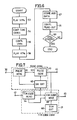
- the operation of the CPU for the case where the time code converting part 15 is constituted by the CPU is shown in the flow chart of FIG. 6.
- a step 53 puts each of the first VTR of the video system 11 and the second VTR of the digital audio system 14 in a play mode.
- a step 54 converts the EBU time code reproduced in the first VTR into an SMPTE time code and compares the converted time code with the SMPTE time code reproduced in the second VTR.
- a step 55 controls the first and second VTRs so that the operation of the second VTR is advanced by twenty frames in frame address compared to the operation of the first VTR.
- a step 56 again puts each of the first and second VTRs in the play mode.
- a step 57 writes into a memory the digital audio signals which are obtained by digitally converting in the digital audio processor within the digital audio system 14 the audio signals which are reproduced in the form of the video signal in the second VTR.
- a step 58 controls the read-out address of the memory from which the digital audio signals are read out responsive to the difference between the compared time codes. The operation of the CPU is ended when a step 59 discriminates that both the first and second VTRs are stopped.
- the read-out address of the memory may be controlled manually.
- the output synchronizing signal of the signal generator 12 is applied to the input terminal 30 and is supplied to a pulse generator 61.
- the pulse generator 61 generates a frame pulse signal shown in FIG. 3(A) having a frequency of 25 Hz which is synchronized with the output synchronizing signal of the signal generator 12, and a clock signal having a frequency which is a multiple of both 25 Hz and 30 Hz.
- the clock signal is used to generate a master clock signal.
- the output frame pulse signal of the signal generator 61 is supplied to a switching circuit 62, and the output clock pulse of the signal generator 61 is supplied to a pulse generator 63.
- the EBU time code from the video system 11 is applied to the input terminal 40 and is supplied to a time code reader 64.
- the time code reader 64 produces the data of the EBU time code, and further, produces a switching signal (control signal) corresponding to the fifth, tenth, fifteenth, twentieth, and zeroth frame addresses of the EBU time code by detecting the fourth, ninth, fourteenth, nineteenth, and twenty-fourth frame addresses of the EBU time code.
- the switching signal has the same waveform as that of the control signal shown in FIG. 3(C).
- the data of the EBU time code is supplied to an SMPTE time code generator 65, and the switching signal is supplied to the switching circuit 62 and the time code generator 65.
- the switching circuit 62 passes out of the 25 Hz frame pulse signal obtained from the pulse generator 61 only the signal parts corresponding to the zeroth, fifth, tenth, fifteenth, and twentieth frame addresses of the EBU time code responsive to the switching signal.
- a pulse signal shown in FIG. 3(D) is obtained from the switching circuit 62 and is supplied to the pulse generator 63.
- the pulse generator 63 generates a frame pulse signal shown in FIG. 3(B) having a frequency of 30 Hz based on the clock signal from the pulse generator 61, with a timing of the pulse signal obtained from the switching circuit 62.
- This frame pulse signal having the frequency of 30 Hz is obtained through the output terminal 44, and is also supplied to the time code generator 65.
- the time code generator 65 detects out of the 30 Hz frame pulse signal obtained from the pulse generator 63 the signal parts corresponding to every sixth pulse responsive to the switching signal described before.
- the time code generator 65 generates an SMPTE time code in accordance with the EBU time code obtained at each point in time when the signal part corresponding to a sixth pulse is detected, and the generated SMPTE time code is obtained through the output terminal 45.
- the timing with which the time code generator 65 operates is controlled by an output signal of a timing circuit 66. Therefore, the SMPTE time code obtained through the output terminal 45 is in synchronism with the EBU time code applied to the input terminal 40.
- the data of the EBU time code obtained from the time code reader 64 at the point in time when a predetermined signal part of the 30 Hz frame pulse signal from the pulse generator 63 is detected by the time code generator 65 responsive to the switching signal indicates twenty-three hours, nineteen minutes, fifty seconds, and frame address five (that is, the fifth frame address)
- an SMPTE time code which starts from twenty-three hours, nineteen minutes, fifty seconds, and frame address six (that is, the sixth frame address) is obtained from the output terminal 45.
- the SMPTE time code may start from either one of the zeroth, sixth, twelfth, eighteenth, and twenty-fourth frame addresses which are respectively in phase synchronism with the zeroth, fifth, tenth, fifteenth, and twentieth frame addresses of the EBU time code.
- the output frame pulse signal of the pulse generator 63, the EBU time code, and the switching signal are respectively synchronized with the output synchronizing signal of the signal generator 12, the synchronism described above between the EBU time code and the SMPTE time code is maintained once the synchronism is obtained between the EBU time code and the SMPTE time code. Accordingly, once the synchronism described above is obtained between the EBU time code and the SMPTE time code, the operation of synchronizing the SMPTE time code with the EBU time code is unnecessary until the two VTRs stop.
- FIG. 8 shows an embodiment of a concrete circuit of an essential part of the block system shown in FIG. 7.
- those parts which are the same as those corresponding parts in FIG. 7 are designated by the same reference numerals, and description thereof will be omitted.
- the clock signal and the 25 Hz frame pulse signal from the pulse generator 61 are applied to respective input terminals 70 and 71.
- the input terminal 70 is coupled to the pulse generator 63 through an inverter 72, and the input terminal 71 is coupled through an inverter 73 to the switching circuit 62 which comprises a NAND gate 74 and an OR gate 75.
- a signal having a frequency of 600 Hz, for example, is applied to an input terminal 76 and is supplied to a timing circuit 77 which comprises an inverter 78, a NAND gate 79, a counter 80, a 1/12 frequency divider 81, a 1/9 frequency divider 82, and a port 83.
- the reproduced EBU time code from the video system 11 is applied to an input terminal 84 and is supplied to the time code reader 64 which comprises a wave shaping circuit 85, an EBU decoder 86, and a port 87.
- a central processing unit (CPU) 88 controls the circuit shown in FIG. 8, and for example, a CPU HD6803 manufactured by Hitachi, Ltd. of Japan may be used for the CPU 88.
- a memory 89 is a read only memory (ROM) or the like which prestores programs.
- An address decoder 90 decodes an address obtained via an address bus 91.
- a port 93 is coupled to a data bus 92, and a port 94 is coupled to the address bus 91.
- a supervisory circuit 95 comprises a NAND gate 96 and a latch circuit 97, and supervises the synchronous state between the 25 Hz frame pulse signal and the 30 Hz frame pulse signal.
- a modulating circuit 103 comprises a port 98, a latch circuit 99, a counter 100, and inverters 101 and 102, and modulates the SMPTE time code.
- a display circuit 106 comprises a port 104 and a transmitter 105, and displays the time code.
- the time code generator 65 comprises a port 107 and an SMPTE encoder 108.
- the circuit shown in FIG. 8 comprises a latch circuit 109, an inverter 110, a counter 111, an oscillator 112, a buffer 113, and transmitters 114 through 117.
- An output terminal group 118 is coupled to the digital audio processor within the digital audio system 14.
- the transmitter 116 is coupled to an output terminal 120 through an amplifier 119, and the transmitter 117 is coupled to an output terminal 122 through an amplifier 121.
- the output terminals 120 and 122 are coupled to a synchronizer (not shown) which operates the video system 11 and the digital audio system 14 while maintaining synchronism between the two systems.
- a step 131 performs an initializing operation such as clearing registers within the CPU 88.
- a step 132 enters the data of the EBU time code obtained from the time code reader 64, and a step 133 discriminates whether or not the data is obtained continuously for three frames and the correct data is obtained. In other words, when the data is obtained continuously for three frames, the step 133 discriminates that the VTR of the video system 11 is operating.
- a step 134 reads the data of the EBU time code.
- a step 135 discriminates whether or not the frame address of the data which is read is the fourth, ninth, fourteenth, nineteenth, or twenty-fourth frame address.
- the discrimination result in the step 135 is NO, the operation is returned to the step 134.
- a step 136 controls the switching circuit 62 so as to pass out of the 25 Hz frame pulse signal supplied to the switching circuit 62 the signal part corresponding to the next frame address, that is, the signal part corresponding to the fifth, tenth, fifteenth, twentieth, or zeroth frame address. Accordingly, the pulse signal shown in FIG. 3(D) is obtained from the switching circuit 62.
- a step 137 generates an SMPTE time code in accordance with the data of the EBU time code which is obtained, and stores the SMPTE time code within the CPU 88. In this state, every sixth pulse of the frame pulse signal obtained from the pulse generator 63 is in phase synchronism with every fifth pulse of the frame pulse signal obtained from the pulse generator 61. Thus, a step 138 controls the switching circuit 62 so that the pulse signal is no longer obtained from the switching circuit 62.
- a step 139 sets an OK flag.
- the OK flag in the set state thereof indicates that the data of the EBU time code is continuous and the data is correct, and that the SMPTE time code which is obtained is synchronized with the EBU time code. For example, the OK flag is set within the synchronizer described before.
- a step 140 discriminates whether or not an interrupt signal for the next frame is obtained from the port 83.
- a step 141 adds a data corresponding to one frame to the data of the SMPTE time code and loads the data which is added with the data corresponding to one frame into the modulating circuit 103.
- a step 142 discriminates whether or not the data of the EBU time code is continuous for seven frames, for example.
- the discrimination result in the step 142 is YES, the operation is returned to the step 140.
- a step 143 resets the OK flag and the operation is returned to the step 131.
- a step 144 discriminates whether or not the data of the EBU time code is identical for three frames, for example.
- the operation is returned to the step 131.
- a step 145 displays the EBU time code and the operation is thereafter returned to the step 131.
- the VTR of the video system 11 employs the PAL system and the VTR of the digital audio system 14 employs the NTSC system.
- the VTR of the video system 11 may employ the NTSC system and the VTR of the digital audio system 14 may employ the PAL system, for example.
- a simple modification may be made to the time code converting part 15 so that the synchronizing signal converting part 13 generates a frame pulse signal of 25 Hz.
- the two different television system in the VTR of the video system and the VTR of the digital audio system are not limited to the PAL system and the NTSC system.
Claims (11)
Applications Claiming Priority (6)
| Application Number | Priority Date | Filing Date | Title |
|---|---|---|---|
| JP196428/84 | 1984-09-19 | ||
| JP59196428A JPS6173489A (ja) | 1984-09-19 | 1984-09-19 | テレビジヨン信号同期変換装置 |
| JP59225039A JPS61102874A (ja) | 1984-10-25 | 1984-10-25 | テレビジョン信号同期装置 |
| JP225039/84 | 1984-10-25 | ||
| JP59236034A JPS61114657A (ja) | 1984-11-09 | 1984-11-09 | テレビジヨン信号同期タイムコ−ド発生装置 |
| JP236034/84 | 1984-11-09 |
Publications (2)
| Publication Number | Publication Date |
|---|---|
| EP0176324A1 EP0176324A1 (de) | 1986-04-02 |
| EP0176324B1 true EP0176324B1 (de) | 1990-04-25 |
Family
ID=27327243
Family Applications (1)
| Application Number | Title | Priority Date | Filing Date |
|---|---|---|---|
| EP19850306688 Expired - Lifetime EP0176324B1 (de) | 1984-09-19 | 1985-09-19 | Gerät zur Synchronisierung verschiedener Fernsehsysteme |
Country Status (2)
| Country | Link |
|---|---|
| EP (1) | EP0176324B1 (de) |
| DE (2) | DE176324T1 (de) |
Families Citing this family (17)
| Publication number | Priority date | Publication date | Assignee | Title |
|---|---|---|---|---|
| JP2733524B2 (ja) * | 1986-11-13 | 1998-03-30 | ソニー株式会社 | 記録装置 |
| US5596419A (en) * | 1987-06-16 | 1997-01-21 | Canon Kabushiki Kaisha | Video system using two different kinds of recording media |
| US5146448A (en) * | 1988-02-04 | 1992-09-08 | Matsushita Electric Industrial Co., Ltd. | Time code recording or reproducing apparatus and time code converter |
| US5091899A (en) * | 1988-02-04 | 1992-02-25 | Matsushita Electric Industrial Co., Ltd. | Time code recording or reproducing apparatus and time code converter |
| GB9011889D0 (en) * | 1990-05-26 | 1990-07-18 | Crowhurst Business Systems | Improvements relating to recording machines |
| DE69320509T2 (de) * | 1992-03-09 | 1999-04-29 | Teac Corp | Verfahren zur seriellen Ausgabe der Bits von neuerschaftenen Synchronisationsdaten oder dergleichen |
| GB2269956B (en) * | 1992-08-21 | 1996-05-15 | Sony Broadcast & Communication | Multiple reference video processing |
| EP0694243B1 (de) * | 1993-04-16 | 2001-08-22 | Avid Technology, Inc. | Verfahren und vorrichtung zur synchronisierung eines bilddatenstromes mit einem korrespondierenden audiodatenstrom |
| DE69524927D1 (de) * | 1994-05-30 | 2002-02-14 | Sony Corp | Bildverarbeitungsgerät und -editiersystem |
| JP2747251B2 (ja) * | 1995-07-24 | 1998-05-06 | 日本電気ホームエレクトロニクス株式会社 | 画像・音声編集システム |
| JP3763153B2 (ja) * | 1995-12-13 | 2006-04-05 | ソニー株式会社 | データ処理装置及びデータ処理方法 |
| US5953073A (en) * | 1996-07-29 | 1999-09-14 | International Business Machines Corp. | Method for relating indexing information associated with at least two indexing schemes to facilitate the play-back of user-specified digital video data and a video client incorporating the same |
| JPH1066036A (ja) * | 1996-08-15 | 1998-03-06 | Oki Electric Ind Co Ltd | Tv方式変換装置 |
| US5857044A (en) * | 1996-09-23 | 1999-01-05 | Sony Corporation | Method and apparatus for processing time code |
| JP2003087733A (ja) * | 2001-09-13 | 2003-03-20 | Matsushita Electric Ind Co Ltd | タイムコード演算方法、およびタイムコード演算装置 |
| DE10322722B4 (de) * | 2003-05-20 | 2005-11-24 | Fraunhofer-Gesellschaft zur Förderung der angewandten Forschung e.V. | Vorrichtung und Verfahren zum Synchronisieren eines Audiossignals mit einem Film |
| DE102006056159B4 (de) * | 2006-11-28 | 2008-08-21 | Fraunhofer-Gesellschaft zur Förderung der angewandten Forschung e.V. | Vorrichtung und Verfahren zum Ermitteln eines Zeitcodeversatzes |
Family Cites Families (5)
| Publication number | Priority date | Publication date | Assignee | Title |
|---|---|---|---|---|
| US4009331A (en) * | 1974-12-24 | 1977-02-22 | Goldmark Communications Corporation | Still picture program video recording composing and playback method and system |
| FR2424606A1 (fr) * | 1978-04-24 | 1979-11-23 | Production Creation Audiovisue | Dispositif de postsynchronisation d'enregistrements magnetoscopiques |
| AU540275B2 (en) * | 1979-09-27 | 1984-11-08 | Sony Corporation | V.t.r. synchronizing system |
| EP0051584A1 (de) * | 1980-05-12 | 1982-05-19 | Magna-Tech Electronic Co. | Verfahren zum mischen von audio- und videosignalen durch anwendung der techniken bewegter bilder |
| JPS5774806A (en) * | 1980-10-28 | 1982-05-11 | Victor Co Of Japan Ltd | Synchronizing reproduction system |
-
1985
- 1985-09-19 DE DE1985306688 patent/DE176324T1/de active Pending
- 1985-09-19 DE DE8585306688T patent/DE3577381D1/de not_active Expired - Fee Related
- 1985-09-19 EP EP19850306688 patent/EP0176324B1/de not_active Expired - Lifetime
Also Published As
| Publication number | Publication date |
|---|---|
| EP0176324A1 (de) | 1986-04-02 |
| DE176324T1 (de) | 1986-06-12 |
| DE3577381D1 (de) | 1990-05-31 |
Similar Documents
| Publication | Publication Date | Title |
|---|---|---|
| EP0176324B1 (de) | Gerät zur Synchronisierung verschiedener Fernsehsysteme | |
| US4772959A (en) | Digital signal recording and reproducing apparatus | |
| US4587573A (en) | Coded signal reproducing apparatus | |
| US5091899A (en) | Time code recording or reproducing apparatus and time code converter | |
| EP0823817B1 (de) | Verfahren und Vorrichtung zur magnetischen Wiedergabe | |
| US5146448A (en) | Time code recording or reproducing apparatus and time code converter | |
| US4903148A (en) | Digital signal editing apparatus | |
| EP0584908B1 (de) | Verarbeitung von Videosignalen unterschiedlicher Bildraten | |
| US5119242A (en) | Apparatus and method for synchronizig audio and video tape players | |
| US4752835A (en) | Audio signal generating apparatus for generating an audio signal to be recorded on a video disc | |
| JPH0251983A (ja) | 静止画像記録装置 | |
| US4266244A (en) | System for detecting the initial point of a digital signal in a composite digital signal reproducing system | |
| JP2685901B2 (ja) | ディジタル信号の信号処理装置 | |
| JPS6336049B2 (de) | ||
| US5181125A (en) | Apparatus for muting noise resulting from reproducing of a PCM audio signal recorded in an extension of a slant track containing a recorded video signal | |
| JPS60111369A (ja) | 記録再生装置 | |
| JPH0723341A (ja) | 信号同期装置 | |
| KR0157556B1 (ko) | 디지탈 브이씨알의 트랙구분신호 생성장치 | |
| JPH02177062A (ja) | ディジタル情報信号記録装置 | |
| JPH0644809B2 (ja) | 音声信号の再生位相制御回路 | |
| JPS6233371A (ja) | 磁気記録再生装置 | |
| JPH10106240A (ja) | タイムコード処理方法及び装置 | |
| JP2947393B2 (ja) | タイムコード信号再生装置 | |
| JPH0462508B2 (de) | ||
| JPH02301087A (ja) | 信号記録装置と信号再生装置 |
Legal Events
| Date | Code | Title | Description |
|---|---|---|---|
| PUAI | Public reference made under article 153(3) epc to a published international application that has entered the european phase |
Free format text: ORIGINAL CODE: 0009012 |
|
| AK | Designated contracting states |
Kind code of ref document: A1 Designated state(s): DE GB NL |
|
| TCNL | Nl: translation of patent claims filed | ||
| DET | De: translation of patent claims | ||
| 17P | Request for examination filed |
Effective date: 19860606 |
|
| 17Q | First examination report despatched |
Effective date: 19890222 |
|
| GRAA | (expected) grant |
Free format text: ORIGINAL CODE: 0009210 |
|
| AK | Designated contracting states |
Kind code of ref document: B1 Designated state(s): DE GB NL |
|
| REF | Corresponds to: |
Ref document number: 3577381 Country of ref document: DE Date of ref document: 19900531 |
|
| PLBE | No opposition filed within time limit |
Free format text: ORIGINAL CODE: 0009261 |
|
| STAA | Information on the status of an ep patent application or granted ep patent |
Free format text: STATUS: NO OPPOSITION FILED WITHIN TIME LIMIT |
|
| 26N | No opposition filed | ||
| PGFP | Annual fee paid to national office [announced via postgrant information from national office to epo] |
Ref country code: GB Payment date: 19950911 Year of fee payment: 11 |
|
| PGFP | Annual fee paid to national office [announced via postgrant information from national office to epo] |
Ref country code: NL Payment date: 19950922 Year of fee payment: 11 |
|
| PGFP | Annual fee paid to national office [announced via postgrant information from national office to epo] |
Ref country code: DE Payment date: 19950928 Year of fee payment: 11 |
|
| PG25 | Lapsed in a contracting state [announced via postgrant information from national office to epo] |
Ref country code: GB Effective date: 19960919 |
|
| PG25 | Lapsed in a contracting state [announced via postgrant information from national office to epo] |
Ref country code: NL Effective date: 19970401 |
|
| GBPC | Gb: european patent ceased through non-payment of renewal fee |
Effective date: 19960919 |
|
| NLV4 | Nl: lapsed or anulled due to non-payment of the annual fee |
Effective date: 19970401 |
|
| PG25 | Lapsed in a contracting state [announced via postgrant information from national office to epo] |
Ref country code: DE Effective date: 19970603 |