EP0173366B1 - A two step electrochemical etch process for high volt aluminium anode foil - Google Patents
A two step electrochemical etch process for high volt aluminium anode foil Download PDFInfo
- Publication number
- EP0173366B1 EP0173366B1 EP85201172A EP85201172A EP0173366B1 EP 0173366 B1 EP0173366 B1 EP 0173366B1 EP 85201172 A EP85201172 A EP 85201172A EP 85201172 A EP85201172 A EP 85201172A EP 0173366 B1 EP0173366 B1 EP 0173366B1
- Authority
- EP
- European Patent Office
- Prior art keywords
- foil
- aluminum
- weight
- current density
- bath
- Prior art date
- Legal status (The legal status is an assumption and is not a legal conclusion. Google has not performed a legal analysis and makes no representation as to the accuracy of the status listed.)
- Expired
Links
- 239000011888 foil Substances 0.000 title claims description 79
- 238000000034 method Methods 0.000 title claims description 47
- XAGFODPZIPBFFR-UHFFFAOYSA-N aluminium Chemical compound [Al] XAGFODPZIPBFFR-UHFFFAOYSA-N 0.000 title claims description 38
- 229910052782 aluminium Inorganic materials 0.000 title claims description 38
- 239000004411 aluminium Substances 0.000 title 1
- VEXZGXHMUGYJMC-UHFFFAOYSA-N Hydrochloric acid Chemical compound Cl VEXZGXHMUGYJMC-UHFFFAOYSA-N 0.000 claims description 28
- 238000005530 etching Methods 0.000 claims description 23
- 239000003792 electrolyte Substances 0.000 claims description 16
- VSCWAEJMTAWNJL-UHFFFAOYSA-K aluminium trichloride Chemical compound Cl[Al](Cl)Cl VSCWAEJMTAWNJL-UHFFFAOYSA-K 0.000 claims description 14
- 239000003990 capacitor Substances 0.000 claims description 11
- VEXZGXHMUGYJMC-UHFFFAOYSA-M Chloride anion Chemical compound [Cl-] VEXZGXHMUGYJMC-UHFFFAOYSA-M 0.000 claims description 4
- 238000004519 manufacturing process Methods 0.000 description 8
- 230000000977 initiatory effect Effects 0.000 description 5
- FAPWRFPIFSIZLT-UHFFFAOYSA-M Sodium chloride Chemical compound [Na+].[Cl-] FAPWRFPIFSIZLT-UHFFFAOYSA-M 0.000 description 4
- 230000000694 effects Effects 0.000 description 4
- 238000001556 precipitation Methods 0.000 description 3
- WNROFYMDJYEPJX-UHFFFAOYSA-K aluminium hydroxide Chemical compound [OH-].[OH-].[OH-].[Al+3] WNROFYMDJYEPJX-UHFFFAOYSA-K 0.000 description 2
- 230000008020 evaporation Effects 0.000 description 2
- 238000001704 evaporation Methods 0.000 description 2
- 239000011780 sodium chloride Substances 0.000 description 2
- GRYLNZFGIOXLOG-UHFFFAOYSA-N Nitric acid Chemical compound O[N+]([O-])=O GRYLNZFGIOXLOG-UHFFFAOYSA-N 0.000 description 1
- QAOWNCQODCNURD-UHFFFAOYSA-L Sulfate Chemical compound [O-]S([O-])(=O)=O QAOWNCQODCNURD-UHFFFAOYSA-L 0.000 description 1
- 230000002378 acidificating effect Effects 0.000 description 1
- 239000010407 anodic oxide Substances 0.000 description 1
- 238000003486 chemical etching Methods 0.000 description 1
- 150000001805 chlorine compounds Chemical class 0.000 description 1
- 239000013078 crystal Substances 0.000 description 1
- 230000003628 erosive effect Effects 0.000 description 1
- 238000009434 installation Methods 0.000 description 1
- 238000009533 lab test Methods 0.000 description 1
- 238000012544 monitoring process Methods 0.000 description 1
- 230000007935 neutral effect Effects 0.000 description 1
- 229910017604 nitric acid Inorganic materials 0.000 description 1
- 150000003839 salts Chemical class 0.000 description 1
Images
Classifications
-
- H—ELECTRICITY
- H01—ELECTRIC ELEMENTS
- H01G—CAPACITORS; CAPACITORS, RECTIFIERS, DETECTORS, SWITCHING DEVICES, LIGHT-SENSITIVE OR TEMPERATURE-SENSITIVE DEVICES OF THE ELECTROLYTIC TYPE
- H01G9/00—Electrolytic capacitors, rectifiers, detectors, switching devices, light-sensitive or temperature-sensitive devices; Processes of their manufacture
- H01G9/004—Details
- H01G9/04—Electrodes or formation of dielectric layers thereon
- H01G9/048—Electrodes or formation of dielectric layers thereon characterised by their structure
- H01G9/055—Etched foil electrodes
-
- C—CHEMISTRY; METALLURGY
- C25—ELECTROLYTIC OR ELECTROPHORETIC PROCESSES; APPARATUS THEREFOR
- C25F—PROCESSES FOR THE ELECTROLYTIC REMOVAL OF MATERIALS FROM OBJECTS; APPARATUS THEREFOR
- C25F3/00—Electrolytic etching or polishing
- C25F3/02—Etching
- C25F3/04—Etching of light metals
Definitions
- the invention relates to the etching of aluminum electrolytic capacitor anode foil of a high cubic texture in a first etching bath at a first current density and followed by a second step using an etching bath and a second current density.
- U.S. Patent No. 4,213,835 discloses a method for electrolytically etching a recrystallized aluminum foil (high cubicity foil) which allows manufacture of foils with exclusively pure cylindrical or cubical etch tunnel structures and tunnel densities greater than 10 7 /cm 2 of foil surface. This process uses a potentiostatic etching technique. The problem with this technique is that it does not lend itself to large scale mass production of etched foils.
- U.S. Patent 4,420,367 discloses a method for etching a recrystallized aluminum foil for electrolytic capacitors by carrying out an electrolytic tunnel etching process in a first etching stage, as is common in the art.
- the improvement of this patent relates to the provision that the continued etching for enlarging the tunnel is nonelectrolytic, being accomplished chemically in one or several etching stages.
- the recrystallized aluminum foil is subjected to electrolytic tunnel formaton to form a tunnel structure in the aluminum and in the second stage the aluminum foil with tunnel structure from the first etching stage is subjected to at least one further nonelectrolytic etching stage to effect tunnel enlargement by chemical etching.
- the present invention is directed to achieving a significant increase in specific capacitance for high volt foils.
- the invention features the etching of aluminum capacitor anode foil having a high cubic texture to produce a more uniformly etched foil and significantly higher capacitance.
- the foil in a first step is etched in an electrolyte bath containing between 1.5 and 7 weight % hydrochloric acid and between 0 and 2 weight % aluminum in the form of aluminum chloride, under the influence of direct current with a current density between 0.25 and 0.60 A/cm 2 , at a temperature of 70° to 85°C, while passing a charge of 6 to 25 C/cm 2 through said foil while said foil is immersed insaid hydrochloric acid bath and in that the foil is subsequently treated in a second electrolyte bath containing of from 1.5 to 7 weight % hydrochloric acid and between 0 and 2.0 weight % aluminum in the form of aluminum chloride, under the influence of direct current with a current density of 0.10 to 0.15 A/ cm 2 , at a temperature of 75° to 90°C, while passing a charge of 40 to 50 C/cm 2 through said foil while said foil is immersed in said second electrolyte bath.
- the resulting foil has a CV ranging up to 368 volt-pF/cM2 for foil formed at 260 volts in production quantities. Laboratory tests indicated that higher values are possible.
- Such coils may be called "non-cubic", foils with less than 25% cubic texture.
- aluminum foils are classified as high cubic.
- an aluminum foil having a high cubic texture, substantially greater than 50% is preferred over foils of lower cubicity because when etched, the tunnel structures are found to be uniform and elongated and the tunnel density can consequently be increased.
- Another major factor controlling the increase in specific capacitance is the etch process which controls the tunnel initiation and the depth and width of the etched tunnels. As shown in Table I, a combination of a suitable choice of both aluminum foil to be etched and an etch process will result in a more uniform tunnel structure, and a much higher capacitance.
- the chemistry of the etch electrolyte in the first step of the present invention is a major factor for controlling the etch characteristics of DC etching of high voltage, e.g. over 200 volt, anode foils.
- Hydrochloric acid is used in preference to other chlorides in this application because it avoids the precipitation of aluminum hydroxide which can clog the very elongated tunnels which are developed in the process of the present invention. If such precipitation is allowed to occur, it will interfere with the high cubic nature of the foil, thereby not fully utilizing the benefits that can be derived when a suitable combination of the high cubic texture foil and the etch process is employed.
- the process of the present invention results in a very efficient and economical two step etch process that yields capacitance values equal to or significantly higher than the best available commercial foils without requiring major changes in existing production machinery.
- the advantages of the inventive process consist in that etched tunnel structures with a tunnel density greater than 10 7 /cm 2 of foil surface are obtained and the etched tunnels are uniformly distributed over the foil. With the help of the inventive process, the highest possible surface enlargement and capacitance gain with the smallest possible aluminum erosion is obtained while maintaining sufficient foil strength.
- aluminum electrolytic capacitor anode foil having a high cubic texture, preferably over 70%, and having a thickness of 70 to 100 pm is in the first step etched by treating the foil with an etch electrolyte bath containing 3% hydrochloric acid and 1% aluminum as a chloride under the influence of DC current at 75°C.
- the current density is 0.31 to 0.45 Alcm 2 and the etch coulombs are 9-15 coulombs/cm 2 .
- this etched foil is treated in a bath containing a similar solution, namely 3% hydrochloric acid, 1% aluminum as aluminum chloride, the solution being maintained between 75° to 85°C, under the influence of DC current.
- the current density is 0.10to 0.15 Alcm 2 and the etch charge is 40 to 50 coulombs/cm 2 .
- the purpose of this solution is the enlargement of the tunnels initiated in the first step.
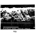
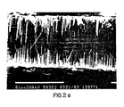
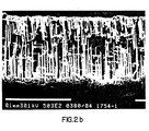
- the figures show tunnel structures of a cross-section of etched foil.
- the linear light grey structures are the etched tunnels of the foil and the boundary surfaces of the foil are slightly discernable above and below the tunnels against the mounting mat.
- the relatively straight, elongated tunnel structure which appears in the vertical plane in the SEM photographs of Figures 2a and 2b is evident.
- the light grey areas which are the tunnels penetrate further through the foil. They appear in a somewhat regular pattern and the density of the tunnel structure is significantly greater than that of the prior art as shown in Figure 1.
- Of key interest in the photographs is the fact that many tunnels do not intersect one another, thereby removiong foil from the structure.
- the amount of aluminum dissolved in terms of mg/cm 2 is about 5.0 to 9.0.
- the following table shows the capacitance of the foil when anodic oxides are formed at 260 V and 456 V.
- the CV number is the capacitance times the voltage and the CV/mg number is the capacitance times the voltage divided by the amount of aluminum dissolved per cm 2 . This number is a measure of the relative efficiency of the etching process.
- the aluminum foil used is a foil having a very high cubic texture which means that this foil has a high orientation of grains in the 100 direction.
- a foil having at least 70 volume % of its grains oriented in the 100 direction is sufficient to achieve the desired results.
- Such foils are commercially available from Showa Aluminum Company, Toyo Aluminum Company, and SCAL, a Division of Pechiney Aluminum Company.
- a high cubicity foil enables the etching of very straight tunnels while retaining surface area created by the etching. The tunnel initiation tends to be more uniform and the tunnel density can then be increased. The higher the cubicity of the foil, the higher the specific capacitance will be. For production purposes, however, it has been empirically determined that the cubicity of 70 volume % or higher will suffice.
- a range of values for the other parameters of the present process is also possible.
- the chemistry of the first step electrolyte is aimed at producing an acidic medium having a large presence of chloride. Hydrochloric acid is used to avoid the precipitation of aluminum hydroxide which would occur with sodium chloride. The introduction of aluminum makes the electrolyte bath less expensive and minimizes electrolyte replacement in the process.
- the range of parameters for the first step electrolyte bath are as follows. Hydrochloric acid is present in concentrations ranging between 1.5 and 7 weight % and the aluminum in the form of chloride is present in the range between 0 and 2 weight %.
- the temperature during the first step is from 70 to 85°C.
- the current density is between 0.25 and 0.60 A/cm 2 .
- the etch charge has a value from 6 to 25 C/cm 2 .
- These ranges have been empirically determined for purposes of mass production of a high volt foil. The latitude in the ranges presented enables high speed mass production of foil without elaborate control systems for monitoring these parameters, thus making the installation of the process of the present invention relatively inexpensive. In terms of the temperature range, over 85°C evaporation becomes a significant factor. If the temperature is lower than 70°C, the etching process either will not work or will work less efficiently in initiating the required number of etched tunnels. In terms of the current density, a density below the low point of the range will result in lower tunnel initiation and consequently, lower tunnel density.
- the tunnel size will tend to be non-uniform because there will be competition between the deepening of the tunnels already initiated and the initiation of new tunnels. As in any etching process, non-uniform tunnels are to be avoided since many in effect will be closed when the anode foil is formed with an oxide at high voltages.
- the range of values for the second step in the process is as follows.
- the amount of hydrochloric acid is from 1.5 to 7 weight % and the amount of aluminum in the form of aluminum chloride is between 0 and 2 weight %.
- the temperature is from 75 to 94°C.
- the current density is from 0.10 to 0.15 Alcm 2 and the etch charge has a value from 40 to 50 C/cm 2 .
- foils etched in accordance with the present invention can be used in high volt electrolytic capacitors and yield a significantly higher specific capacitance per cm 2 than previously obtained.
- the capacitor can have a smaller volume or of the same volume can have a higher capicitance.
Landscapes
- Engineering & Computer Science (AREA)
- Chemical & Material Sciences (AREA)
- Power Engineering (AREA)
- Chemical Kinetics & Catalysis (AREA)
- Electrochemistry (AREA)
- Materials Engineering (AREA)
- Metallurgy (AREA)
- Organic Chemistry (AREA)
- Microelectronics & Electronic Packaging (AREA)
- ing And Chemical Polishing (AREA)
- Fixed Capacitors And Capacitor Manufacturing Machines (AREA)
- Cell Electrode Carriers And Collectors (AREA)
Applications Claiming Priority (2)
| Application Number | Priority Date | Filing Date | Title |
|---|---|---|---|
| US645876 | 1984-08-29 | ||
| US06/645,876 US4518471A (en) | 1984-08-29 | 1984-08-29 | Two step electrochemical etch process for high volt aluminum anode foil |
Publications (2)
| Publication Number | Publication Date |
|---|---|
| EP0173366A1 EP0173366A1 (en) | 1986-03-05 |
| EP0173366B1 true EP0173366B1 (en) | 1989-01-25 |
Family
ID=24590837
Family Applications (1)
| Application Number | Title | Priority Date | Filing Date |
|---|---|---|---|
| EP85201172A Expired EP0173366B1 (en) | 1984-08-29 | 1985-07-12 | A two step electrochemical etch process for high volt aluminium anode foil |
Country Status (4)
| Country | Link |
|---|---|
| US (1) | US4518471A (enExample) |
| EP (1) | EP0173366B1 (enExample) |
| JP (1) | JPS61159600A (enExample) |
| DE (1) | DE3567915D1 (enExample) |
Families Citing this family (51)
| Publication number | Priority date | Publication date | Assignee | Title |
|---|---|---|---|---|
| JP2692108B2 (ja) * | 1988-02-19 | 1997-12-17 | 松下電器産業株式会社 | アルミ電解コンデンサ用電極箔の製造方法 |
| DE4001466A1 (de) * | 1990-01-19 | 1991-07-25 | Hoechst Ag | Verfahren zur elektrochemischen aufrauhung von aluminium fuer druckplattentraeger |
| US5186795A (en) * | 1991-07-22 | 1993-02-16 | Eastman Kodak Company | Two-stage process for electrolytic graining of aluminum |
| US5122243A (en) * | 1991-07-22 | 1992-06-16 | Eastman Kodak Company | Lithographic printing plates comprising an aluminum support grained in a two stage-electrolytic process |
| WO1993001942A1 (en) * | 1991-07-22 | 1993-02-04 | Eastman Kodak Company | Two-stage electrolytic graining process, aluminum sheet material produced thereby and lithographic printing plate comprising such aluminum sheet material |
| DE4129909A1 (de) * | 1991-09-09 | 1993-03-11 | Hoechst Ag | Verfahren zum aufrauhen von aluminium bzw. von aluminiumlegierungen als traegermaterial fuer druckplatten und eine druckplatte |
| JP2907718B2 (ja) * | 1993-12-29 | 1999-06-21 | 昭和アルミニウム株式会社 | 電解コンデンサ電極用アルミニウム箔のエッチング方法 |
| JP2787801B2 (ja) * | 1994-03-10 | 1998-08-20 | 日本蓄電器工業株式会社 | 電解コンデンサ用アルミニウム電極箔のエッチング方法 |
| US5922215A (en) * | 1996-10-15 | 1999-07-13 | Pacesetter, Inc. | Method for making anode foil for layered electrolytic capacitor and capacitor made therewith |
| US6168706B1 (en) | 1998-12-11 | 2001-01-02 | Pacesetter, Inc. | Process for producing high etch gains for electrolytic capacitor manufacturing |
| US6238810B1 (en) | 1999-04-07 | 2001-05-29 | Pacesetter, Inc. | Process for using surface active agents to produce high etch gains for electrolytic capacitor manufacturing |
| US6224738B1 (en) | 1999-11-09 | 2001-05-01 | Pacesetter, Inc. | Method for a patterned etch with electrolytically grown mask |
| US6736956B1 (en) | 2001-05-07 | 2004-05-18 | Pacesetter, Inc. | Non-uniform etching of anode foil to produce higher capacitance gain without sacrificing foil strength |
| US6802954B1 (en) | 2002-07-18 | 2004-10-12 | Pacesetter, Inc. | Creation of porous anode foil by means of an electrochemical drilling process |
| US6743370B1 (en) | 2002-05-23 | 2004-06-01 | Pacesetter, Inc. | Conductive electrolyte for high voltage capacitors |
| US6858126B1 (en) | 2002-11-06 | 2005-02-22 | Pacesetter, Inc. | High capacitance anode and system and method for making same |
| US6744619B1 (en) | 2002-12-12 | 2004-06-01 | Pacesetter, Inc. | Conductive electrolyte system with viscosity reducing co-solvents |
| US7268996B1 (en) | 2003-01-10 | 2007-09-11 | Pacesetter, Inc. | Electrolyte for very high voltage electrolytic capacitors |
| US7169284B1 (en) | 2003-09-22 | 2007-01-30 | Pacesetter, Inc. | High surface area cathode for electrolytic capacitors using conductive polymer |
| US7452473B1 (en) | 2003-10-06 | 2008-11-18 | Pacesetter, Inc. | Laser marking of raw aluminum anode foil to induce uniform patterning etching |
| US7150767B1 (en) | 2003-11-03 | 2006-12-19 | Pacesetter, Inc. | Method for producing an electrode for a capacitor from foil |
| CN1954396A (zh) * | 2004-03-08 | 2007-04-25 | 维世-Bc元件公司 | 高电容量的电解电容器箔、其制造方法以及电解电容器 |
| US7175676B1 (en) | 2004-03-29 | 2007-02-13 | Pacesetter, Inc. | Process for manufacturing high-stability crystalline anodic aluminum oxide for pulse discharge capacitors |
| US7715174B1 (en) | 2004-05-17 | 2010-05-11 | Pacesetter, Inc. | Electrolytic capacitors with alternate cathode materials for use in pulse discharge applications |
| US7578924B1 (en) | 2004-07-29 | 2009-08-25 | Pacesetter, Inc. | Process for producing high etch gains for electrolytic capacitor manufacturing |
| US7445646B1 (en) | 2004-08-06 | 2008-11-04 | Pacesetter, Inc. | Method of producing an anode for an electrolytic capacitor |
| US7006347B1 (en) | 2004-08-12 | 2006-02-28 | Pacesetter, Inc. | Low deformation electrolytic capacitor |
| US7531010B1 (en) | 2005-01-07 | 2009-05-12 | Pacesetter, Inc. | Design for capacitor anode assembly |
| US7196899B1 (en) | 2005-01-07 | 2007-03-27 | Pacesetter, Inc. | Capacitor anode assembly |
| US7385802B1 (en) | 2005-10-05 | 2008-06-10 | Pacesetter Inc. | Electrolytic capacitor |
| JP4695966B2 (ja) * | 2005-11-17 | 2011-06-08 | ニチコン株式会社 | 電解コンデンサ用アルミニウム電極箔の製造方法 |
| US7485240B1 (en) | 2006-06-29 | 2009-02-03 | Pacesetter, Inc. | Electrolyte for high voltage electrolytic capacitors |
| CN101029413B (zh) * | 2006-12-19 | 2010-05-12 | 东莞市东阳光电容器有限公司 | 中高压阳极箔的腐蚀箔制造方法 |
| US7585428B1 (en) | 2007-04-05 | 2009-09-08 | Pacesetter, Inc. | Electrolyte with enhanced leakage detection for electrolytic capacitors and method for detecting leakage |
| US8535507B1 (en) | 2008-01-11 | 2013-09-17 | Pacesetter, Inc. | Electrochemical drilling system and process for improving electrical porosity of etched anode foil |
| US8206600B2 (en) * | 2008-09-15 | 2012-06-26 | Pacesetter, Inc. | Nanoimprinting of an optic to control the etch pattern on electrolytic capacitor foil |
| CN101880906B (zh) * | 2009-05-04 | 2012-11-07 | 新疆众和股份有限公司 | 特高压铝电解电容器用阳极箔腐蚀方法及其电解液 |
| US9275800B2 (en) * | 2013-12-19 | 2016-03-01 | Pacesetter, Inc. | Method of nano-patterning a foil surce |
| US9090986B1 (en) | 2014-01-30 | 2015-07-28 | Pacesetter, Inc. | Method for making electrode foils having reduced particle detachment and reduced leakage current |
| CN104630871B (zh) * | 2015-01-13 | 2017-08-18 | 肇庆华锋电子铝箔股份有限公司 | 一种低压硬质高比容铝电极箔的腐蚀工艺方法 |
| US10072349B2 (en) | 2016-01-05 | 2018-09-11 | Pacesetter, Inc. | Etch solutions having bis(perfluoroalkylsulfonyl)imides, and use thereof to form anode foils with increased capacitance |
| US9978529B2 (en) | 2016-01-11 | 2018-05-22 | Pacesetter, Inc. | Oxide on edges of metal anode foils |
| US10090112B2 (en) | 2016-01-15 | 2018-10-02 | Pacesetter, Inc. | Use of etch resist masked anode frame for facilitation of laser cutting, particle and leakage current reduction |
| US9969030B2 (en) | 2016-05-12 | 2018-05-15 | Pacesetter, Inc. | Laser drilling of metal foils for assembly in an electrolytic capacitor |
| US9852849B2 (en) | 2016-05-27 | 2017-12-26 | Pacesetter, Inc. | Using etch resist patterns and formation for facilitation of laser cutting, particle and leakage current reduction |
| US9976226B2 (en) | 2016-07-28 | 2018-05-22 | Pacesetter, Inc. | Method of stressing oxides |
| US10309033B2 (en) | 2016-12-02 | 2019-06-04 | Pacesetter, Inc. | Process additives to reduce etch resist undercutting in the manufacture of anode foils |
| US10422050B2 (en) | 2016-12-02 | 2019-09-24 | Pacesetter, Inc. | Process for using persulfate in a low pH etch solution to increase aluminum foil capacitance |
| US10240249B2 (en) | 2016-12-02 | 2019-03-26 | Pacesetter, Inc. | Use of nonafluorobutanesulfonic acid in a low pH etch solution to increase aluminum foil capacitance |
| JP2018119184A (ja) * | 2017-01-26 | 2018-08-02 | 株式会社Adeka | 電解エッチング液組成物、電解エッチング方法、電解エッチングされた基材、アルミニウム電解コンデンサ用電極材、及びコンデンサ |
| US10894157B2 (en) | 2017-04-04 | 2021-01-19 | Pacesetter, Inc. | Laser marking of raw anode foil to induce uniform pattering and etching with oxide passivation mask |
Family Cites Families (7)
| Publication number | Priority date | Publication date | Assignee | Title |
|---|---|---|---|---|
| JPS5125439A (enExample) * | 1974-08-28 | 1976-03-02 | Fujitsu Ltd | |
| DE2801218C3 (de) * | 1978-01-12 | 1980-11-20 | Siemens Ag, 1000 Berlin Und 8000 Muenchen | Verfahren zum elektrolytischen Ätzen einer rekristallisierten Aluminiumfolie und deren Verwendung |
| JPS5766616A (en) * | 1980-10-13 | 1982-04-22 | Showa Aluminium Co Ltd | Method of producing alumihum foil for electrolytic condenser electrode |
| JPS6059982B2 (ja) * | 1980-12-09 | 1985-12-27 | 昭和アルミニウム株式会社 | 電解コンデンサ電極用アルミニウム箔の製造方法 |
| DE3118151A1 (de) * | 1981-05-07 | 1982-12-02 | Siemens AG, 1000 Berlin und 8000 München | Verfahren zum aetzen einer rekristallisierten aluminiumfolie fuer elektrolytkondensatoren |
| DE3125975A1 (de) * | 1981-07-01 | 1983-01-20 | Siemens AG, 1000 Berlin und 8000 München | Verfahren zur herstellung einer elektrodenfolie fuer elektrolytkondensatoren |
| US4474657A (en) * | 1983-12-20 | 1984-10-02 | North American Philips Corporation | Single step electro chemical etch process for high volt aluminum anode foil |
-
1984
- 1984-08-29 US US06/645,876 patent/US4518471A/en not_active Expired - Fee Related
-
1985
- 1985-07-12 DE DE8585201172T patent/DE3567915D1/de not_active Expired
- 1985-07-12 EP EP85201172A patent/EP0173366B1/en not_active Expired
- 1985-08-29 JP JP60190901A patent/JPS61159600A/ja active Granted
Also Published As
| Publication number | Publication date |
|---|---|
| JPH0557360B2 (enExample) | 1993-08-23 |
| US4518471A (en) | 1985-05-21 |
| DE3567915D1 (en) | 1989-03-02 |
| EP0173366A1 (en) | 1986-03-05 |
| JPS61159600A (ja) | 1986-07-19 |
Similar Documents
| Publication | Publication Date | Title |
|---|---|---|
| EP0173366B1 (en) | A two step electrochemical etch process for high volt aluminium anode foil | |
| EP0171835B1 (en) | A process of etching aluminium anode foil for high voltage electrolytic capacitors | |
| EP0147896B1 (en) | Electrochemical etching of high voltage aluminium anode foil | |
| US4420367A (en) | Method for etching a recrystallized aluminum foil for electrolytic capacitors | |
| US5503718A (en) | Method of etching aluminum foil for electrolytic capacitors | |
| EP0165318B1 (en) | Process for producing anode foil for use in electrolytic aluminum capacitor | |
| CA1236383A (en) | Etching of aluminum electrolytic capacitor foil | |
| CN1006001B (zh) | 高压铝阳极箔的两步电化学和化学蚀刻法 | |
| JPH08264391A (ja) | 電解コンデンサ用アルミニウム箔のエッチング方法 | |
| US3337434A (en) | Method of electrolytic etching metals using a gel electrolyte | |
| JPH03104207A (ja) | 電解コンデンサ用電極のエッチング方法 | |
| JPH07235456A (ja) | 電解コンデンサ用アルミニウム箔のエッチング方法 | |
| CN1005198B (zh) | 高压铝阳极箔两步电化学蚀刻方法 | |
| JPH04305911A (ja) | 電解コンデンサ用アルミニウム箔の製造方法 | |
| Hoare et al. | Electrochemical Machining | |
| JPH07272983A (ja) | アルミ電解コンデンサ用電極箔およびその製造方法 | |
| KR930003433B1 (ko) | 전해 콘덴서용 알루미늄박의 에칭액 및 이를 사용하는 에칭방법 | |
| GB2100751A (en) | Electrolytically etching aluminium | |
| CN106098380A (zh) | 高压阳极箔二级扩孔的孔形控制方法 | |
| SU1674787A1 (ru) | Способ получени инструмента дл обработки металлических поверхностей | |
| JPS63299309A (ja) | アルミニウム電解コンデンサ用電極箔の製造方法 | |
| JPS5935175B2 (ja) | 電解コンデンサ用アルミニウム電極箔の製造方法 | |
| JP2000282299A (ja) | 均一深さのトンネル状ピットを有する電解箔、それを電極とする電解コンデンサー並びに該箔の製造方法 | |
| JPH05152170A (ja) | 電解コンデンサ用アルミニウム合金及び電解コンデンサ用アルミ箔の製造方法 | |
| JPH0567544A (ja) | 電解コンデンサ用アルミニウム箔のエツチング方法 |
Legal Events
| Date | Code | Title | Description |
|---|---|---|---|
| PUAI | Public reference made under article 153(3) epc to a published international application that has entered the european phase |
Free format text: ORIGINAL CODE: 0009012 |
|
| AK | Designated contracting states |
Kind code of ref document: A1 Designated state(s): CH DE FR GB IT LI |
|
| 17P | Request for examination filed |
Effective date: 19860829 |
|
| 17Q | First examination report despatched |
Effective date: 19870731 |
|
| GRAA | (expected) grant |
Free format text: ORIGINAL CODE: 0009210 |
|
| AK | Designated contracting states |
Kind code of ref document: B1 Designated state(s): CH DE FR GB IT LI |
|
| REF | Corresponds to: |
Ref document number: 3567915 Country of ref document: DE Date of ref document: 19890302 |
|
| ITF | It: translation for a ep patent filed | ||
| ET | Fr: translation filed | ||
| PGFP | Annual fee paid to national office [announced via postgrant information from national office to epo] |
Ref country code: CH Payment date: 19891027 Year of fee payment: 5 |
|
| PLBE | No opposition filed within time limit |
Free format text: ORIGINAL CODE: 0009261 |
|
| STAA | Information on the status of an ep patent application or granted ep patent |
Free format text: STATUS: NO OPPOSITION FILED WITHIN TIME LIMIT |
|
| 26N | No opposition filed | ||
| PG25 | Lapsed in a contracting state [announced via postgrant information from national office to epo] |
Ref country code: LI Effective date: 19900731 Ref country code: CH Effective date: 19900731 |
|
| REG | Reference to a national code |
Ref country code: CH Ref legal event code: PL |
|
| PGFP | Annual fee paid to national office [announced via postgrant information from national office to epo] |
Ref country code: GB Payment date: 19920630 Year of fee payment: 8 |
|
| PGFP | Annual fee paid to national office [announced via postgrant information from national office to epo] |
Ref country code: FR Payment date: 19920729 Year of fee payment: 8 |
|
| ITTA | It: last paid annual fee | ||
| PGFP | Annual fee paid to national office [announced via postgrant information from national office to epo] |
Ref country code: DE Payment date: 19920928 Year of fee payment: 8 |
|
| PG25 | Lapsed in a contracting state [announced via postgrant information from national office to epo] |
Ref country code: GB Effective date: 19930712 |
|
| GBPC | Gb: european patent ceased through non-payment of renewal fee |
Effective date: 19930712 |
|
| PG25 | Lapsed in a contracting state [announced via postgrant information from national office to epo] |
Ref country code: FR Effective date: 19940331 |
|
| PG25 | Lapsed in a contracting state [announced via postgrant information from national office to epo] |
Ref country code: DE Effective date: 19940401 |
|
| REG | Reference to a national code |
Ref country code: FR Ref legal event code: ST |