EP0171973B1 - Flow stop control method for casting withdrawal control of horizontal continuous casting machine - Google Patents
Flow stop control method for casting withdrawal control of horizontal continuous casting machine Download PDFInfo
- Publication number
- EP0171973B1 EP0171973B1 EP85305448A EP85305448A EP0171973B1 EP 0171973 B1 EP0171973 B1 EP 0171973B1 EP 85305448 A EP85305448 A EP 85305448A EP 85305448 A EP85305448 A EP 85305448A EP 0171973 B1 EP0171973 B1 EP 0171973B1
- Authority
- EP
- European Patent Office
- Prior art keywords
- withdrawing
- hydraulic motor
- braking
- braking torque
- cycle
- Prior art date
- Legal status (The legal status is an assumption and is not a legal conclusion. Google has not performed a legal analysis and makes no representation as to the accuracy of the status listed.)
- Expired
Links
Images

Classifications
-
- B—PERFORMING OPERATIONS; TRANSPORTING
- B22—CASTING; POWDER METALLURGY
- B22D—CASTING OF METALS; CASTING OF OTHER SUBSTANCES BY THE SAME PROCESSES OR DEVICES
- B22D11/00—Continuous casting of metals, i.e. casting in indefinite lengths
- B22D11/16—Controlling or regulating processes or operations
- B22D11/20—Controlling or regulating processes or operations for removing cast stock
Definitions
- the present invention relates to a method of controlling the extraction of a cast strand for ensuring the desired stop condition in a casting withdrawal control of a horizontal continuous casting machine, according to the preamble of claim 1 and to an apparatus, according to the preamble of claim 2.
- Stop control methods are described in Iron and Steel Engineer, June 1984, pages 65-71 in an article by M. Haissig entitled “Horizontal Continuous Casting: A technology for the future", upon which the preambles of claim 1 and 2 are based.
- this unstable braking torque is applied even during the withdrawing period and the push-back period, other than during the casting flow stop in the stopping period of the withdrawing cycle.
- the unstable braking torque is achieved by contradictory action, due to the flow stopping action during the stopping period and the load torque during the withdrawing period, and the withdrawing waveform tends to become unstable.
- the above-mentioned conventional flow stop control method makes no allowance ' for such load variations and the control is effected by use of the unstable braking torque thus making it difficult to ensure a stable stop condition.
- the stopping period in the withdrawing cycle is the period of time required for the growth of a shell to be newly formed so that if this stopping period is not stably ensured, the growth of the shell is incomplete and a rupture (breaking apart) of the shell occurs during the next withdrawing step thus making it difficult to ensure the stable casting operation.
- a control method and an apparatus in which a braking torque is calculated in on the basis of the inertial loads varying in dependence on the casting condition and the braking torque is applied to the pinch roll shafts thereby effecting the flow stop of a casting during the stopping period of a casting withdrawing cycle within a predetermined period of time, according to the features as laid out in the characterizing portions of claims 1 and 2.
- a casting flow stop control method applies to the pinch roll shafts a braking torque produced by controlling the internal pressure of a braking hydraulic motor through a high-speed pressure control loop.
- any given constant braking torque can be applied and thus the control can be effected quantitatively as compared with the conventional control method.
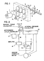
- Fig. 1 is a schematic diagram showing the construction of a horizontal continuous casting machine.
- numeral 1 designates a driving hydraulic motor including a servo valve 2, which is connected to pinch roll shafts 5 of pinch rolls 4 through a gear train 3 and the pinch rolls 4 are driven by the rotation of the driving hydraulic motor 1 controlled by the servo valve 2 thereby withdrawing a billet 6.
- Numeral 7 designates a braking hydraulic motor connected to the gear train 3 through a gear 8 and the flow rate of the braking hydraulic motor 7 is restricted by a throttle valve 9 thereby applying a braking torque in the withdrawing direction of the pinch rolls 4.
- the withdrawing cycle of the horizontal continuous casting machine consists of a withdrawing period t 1 , a stopping period t 2 and a push-back period t 3 as shown in Fig. 3A and during the withdrawing period t 1 the withdrawal of a casting is effected in accordance with the final withdrawing speed V. shown in Fig. 3A and the pressure difference between the inlet and outlet sides of the driving hydraulic motor or the final withdrawing pressure ⁇ Po shown in Fig. 3B.
- the required braking torque T for holding the flow time of the casting within a predetermined flow time td is given by the following equation in accordance with the final withdrawing speed V o and the final withdrawing pressure APo.
- the braking torque T shown by the equation (1) represents the difference value between the negative acceleration torque that must be applied to the billet and the casting loss torque such as the frictional torque and in principle the flow of the billet can be stopped within the preset flow time td by the application of the braking torque T during the deceleration.
- Fig. 2 shows the construction of a control system used with the invention, in which numeral 7 designates the braking hydraulic motor shown in Fig. 1 and numeral 10 designates an oil tank.
- the braking torque T shown by the equation (1) is computed by braking torque computing means 12 in accordance with the final withdrawing speed V o and the final withdrawing pressure APo during the withdrawing period t, of the withdrawing cycle qnd the preset flow time td and braking hydraulic motor internal pressure computing means 13 calculates a braking hydraulic motor internal pressure ⁇ Pb from the calculated braking torque T.
- the braking hydraulic motor internal pressure ⁇ Pb is calculated from the following equation in accordance with the braking torque T.
- the braking hydraulic motor internal pressure ⁇ Pb is applied to an amplifier 14 through a change-over switch 16 so that as for example, the opening of a proportional electromagnetic control valve 15 connected between the braking hydraulic motor 7 and the oil tank 10 is varied by the output signal from the amplifier 14 and the internal pressure of the braking hydraulic motor 7 is controlled.
- the change-over switch 16 is responsive to the end of withdrawing period t 1 signal from withdrawing cycle control means 17 to apply the braking hydraulic motor internal pressure ⁇ Pb signal to the amplifier 14.
- a check valve 11 is connected in parallel with the proportional control valve 15 to prevent the pressure from being applied to the push-back side.
- Figs. 3A, 3B and 3C show various characteristics during the withdrawing cycle according to the flow stop control method which controls the internal pressure of the braking hydraulic motor through the high-speed pressure control loop.
- Fig. 3A shows the withdrawing speed characteristic
- Fig. 3B the driving hydraulic motor internal pressure characteristic
- Fig. 3C the braking hydraulic motor internal pressure characteristic.
- the withdrawing cycle control means 17 detects the reduction of the withdrawing speed to zero so that the change-over switch 16 is switched and the braking hydraulic motor internal pressure APb is reduced to zero.
- control method includes the braking hydraulic motor flow stop control system
- similar function can also be performed by providing a flow stop control system in which the braking hydraulic motor is not used and the driving hydraulic motor itself applies a negative acceleration torque (braking torque) to the pinch roll shafts.
- the required driving hydraulic motor internal pressure AP' for causing the driving hydraulic motor to generate the desired negative acceleration torque (braking torque) T is given by the following in accordance with the equation (1)
Landscapes
- Engineering & Computer Science (AREA)
- Mechanical Engineering (AREA)
- Continuous Casting (AREA)
- Fluid-Pressure Circuits (AREA)
- Injection Moulding Of Plastics Or The Like (AREA)
Priority Applications (1)
| Application Number | Priority Date | Filing Date | Title |
|---|---|---|---|
| AT85305448T ATE43082T1 (de) | 1984-08-09 | 1985-07-31 | Kontrollverfahren waehrend einer durchflussunterbrechung beim steuern des strangausziehens in einer horizontalstranggussmaschine. |
Applications Claiming Priority (2)
| Application Number | Priority Date | Filing Date | Title |
|---|---|---|---|
| JP165600/84 | 1984-08-09 | ||
| JP59165600A JPS6146364A (ja) | 1984-08-09 | 1984-08-09 | 水平連続鋳造機における鋳片の流れ止め制御方法 |
Publications (3)
| Publication Number | Publication Date |
|---|---|
| EP0171973A2 EP0171973A2 (en) | 1986-02-19 |
| EP0171973A3 EP0171973A3 (en) | 1986-12-30 |
| EP0171973B1 true EP0171973B1 (en) | 1989-05-17 |
Family
ID=15815428
Family Applications (1)
| Application Number | Title | Priority Date | Filing Date |
|---|---|---|---|
| EP85305448A Expired EP0171973B1 (en) | 1984-08-09 | 1985-07-31 | Flow stop control method for casting withdrawal control of horizontal continuous casting machine |
Country Status (8)
| Country | Link |
|---|---|
| US (1) | US4660618A (ja) |
| EP (1) | EP0171973B1 (ja) |
| JP (1) | JPS6146364A (ja) |
| KR (1) | KR900003221B1 (ja) |
| AT (1) | ATE43082T1 (ja) |
| CA (1) | CA1230731A (ja) |
| DE (1) | DE3570195D1 (ja) |
| ES (1) | ES8608968A1 (ja) |
Families Citing this family (1)
| Publication number | Priority date | Publication date | Assignee | Title |
|---|---|---|---|---|
| JP2900594B2 (ja) * | 1990-11-21 | 1999-06-02 | 日本鋼管株式会社 | 水平連続鋳造の引抜き制御方法 |
Family Cites Families (6)
| Publication number | Priority date | Publication date | Assignee | Title |
|---|---|---|---|---|
| JPS5659570A (en) * | 1979-10-17 | 1981-05-23 | Nippon Kokan Kk <Nkk> | Driving method of ingot drawing roll in horizontal continuous casting machine |
| JPS5684159A (en) * | 1979-12-11 | 1981-07-09 | Kawasaki Steel Corp | Pinch roll speed control device |
| AT381882B (de) * | 1980-11-18 | 1986-12-10 | Ver Edelstahlwerke Ag | Vorrichtung zum horizontalen stranggiessen |
| JPS601108B2 (ja) * | 1981-07-28 | 1985-01-11 | 新日本製鐵株式会社 | 鋼の連続鋳造方法 |
| JPS6055213B2 (ja) * | 1982-01-13 | 1985-12-04 | 古河電気工業株式会社 | 水平連続鋳造用鋳塊引出し装置 |
| US4513806A (en) * | 1983-05-23 | 1985-04-30 | Kabushiki Kaisha Kobe Seiko Sho | Apparatus for withdrawing solidified rod in horizontal type continuous casting machines |
-
1984
- 1984-08-09 JP JP59165600A patent/JPS6146364A/ja active Granted
-
1985
- 1985-07-31 CA CA000487906A patent/CA1230731A/en not_active Expired
- 1985-07-31 DE DE8585305448T patent/DE3570195D1/de not_active Expired
- 1985-07-31 AT AT85305448T patent/ATE43082T1/de active
- 1985-07-31 EP EP85305448A patent/EP0171973B1/en not_active Expired
- 1985-08-02 KR KR1019850005580A patent/KR900003221B1/ko not_active Expired
- 1985-08-08 ES ES545998A patent/ES8608968A1/es not_active Expired
- 1985-08-09 US US06/764,131 patent/US4660618A/en not_active Expired - Fee Related
Non-Patent Citations (1)
| Title |
|---|
| Iron and Steel Engineer,June 1984,pages 65-71,"Horizontal Continuous Casting: a technology for the future". * |
Also Published As
| Publication number | Publication date |
|---|---|
| JPS6146364A (ja) | 1986-03-06 |
| JPH0523856B2 (ja) | 1993-04-06 |
| ES545998A0 (es) | 1986-07-16 |
| DE3570195D1 (en) | 1989-06-22 |
| EP0171973A2 (en) | 1986-02-19 |
| ES8608968A1 (es) | 1986-07-16 |
| ATE43082T1 (de) | 1989-06-15 |
| CA1230731A (en) | 1987-12-29 |
| US4660618A (en) | 1987-04-28 |
| KR860001627A (ko) | 1986-03-20 |
| KR900003221B1 (ko) | 1990-05-11 |
| EP0171973A3 (en) | 1986-12-30 |
Similar Documents
| Publication | Publication Date | Title |
|---|---|---|
| DE602004012366T2 (de) | Vorrichtung zum Erfassen des Fahrverhaltens eines Fahrzeugs und Vorrichtung zum Steuern des Fahrverhaltens eines Fahrzeugs | |
| DE3627580A1 (de) | Verfahren zum steuern eines krans | |
| KR950005660A (ko) | 차량브레이킹 및 제어를 최대로 하는 방법 및 장치 | |
| EP0182468B1 (en) | Method of changing width of slab in continuous casting | |
| JPH03500520A (ja) | 牽引車によって牽引されている航空機の前輪装置の過剰負荷を防止する方法及び該方法を実施するための牽引車 | |
| EP0352276B1 (de) | Antriebsschlupfregelsystem | |
| US20170355266A1 (en) | Speed control device of electromotive vehicle | |
| EP0171973B1 (en) | Flow stop control method for casting withdrawal control of horizontal continuous casting machine | |
| EP0151929B1 (en) | Method of controlling unequal circumferential speed rolling | |
| DE19722174C2 (de) | Antiblockierbremssteuersystem für Kraftfahrzeuge und zugehöriges Bremskraftsteuerverfahren | |
| IT8922261A1 (it) | Procedimento e disposizione per regolare la forza motrice e/o frenante di motori di trazione di una motrice senza asse portante al limite d'aderenza delle ruote | |
| CA2087825A1 (en) | Method and apparatus for variably controlling the speed of a slave drive roller | |
| CN107214312B (zh) | 连铸大压下量时的力矩控制方法和压下设备 | |
| JP2569446B2 (ja) | 吊り荷の振れ止め運転制御方法 | |
| JP2666959B2 (ja) | 懸垂式クレーンの振れ止め制御方法 | |
| EP0071448B1 (en) | Method of continuous casting of steel and apparatus therefor | |
| JPH03177218A (ja) | 鋳型を間欠的に推進させる方法およびそれに用いる装置 | |
| JPS6163349A (ja) | 水平連続鋳造設備における鋳片押戻量制御方法 | |
| RU2074503C1 (ru) | Способ управления многодвигательным электроприводом и устройство для его осуществления | |
| DE3531653A1 (de) | Antriebs- und bremseinrichtung fuer schienenfahrzeuge | |
| SU1735810A2 (ru) | Устройство дл управлени накопителем полосы | |
| JPS6096357A (ja) | 水平連続鋳造機のピンチロ−ル駆動装置 | |
| JPS55100852A (en) | Direct rolling type continuous casting method | |
| JPS5747509A (en) | Controlling method for speed of direct rolling mill united with continuous casting machine | |
| JPS54133462A (en) | Direct rolling mill |
Legal Events
| Date | Code | Title | Description |
|---|---|---|---|
| PUAI | Public reference made under article 153(3) epc to a published international application that has entered the european phase |
Free format text: ORIGINAL CODE: 0009012 |
|
| AK | Designated contracting states |
Designated state(s): AT BE CH DE FR GB IT LI LU NL SE |
|
| PUAL | Search report despatched |
Free format text: ORIGINAL CODE: 0009013 |
|
| AK | Designated contracting states |
Kind code of ref document: A3 Designated state(s): AT BE CH DE FR GB IT LI LU NL SE |
|
| 17P | Request for examination filed |
Effective date: 19870220 |
|
| 17Q | First examination report despatched |
Effective date: 19870911 |
|
| ITF | It: translation for a ep patent filed | ||
| GRAA | (expected) grant |
Free format text: ORIGINAL CODE: 0009210 |
|
| AK | Designated contracting states |
Kind code of ref document: B1 Designated state(s): AT BE CH DE FR GB IT LI LU NL SE |
|
| REF | Corresponds to: |
Ref document number: 43082 Country of ref document: AT Date of ref document: 19890615 Kind code of ref document: T |
|
| REF | Corresponds to: |
Ref document number: 3570195 Country of ref document: DE Date of ref document: 19890622 |
|
| ET | Fr: translation filed | ||
| PLBE | No opposition filed within time limit |
Free format text: ORIGINAL CODE: 0009261 |
|
| STAA | Information on the status of an ep patent application or granted ep patent |
Free format text: STATUS: NO OPPOSITION FILED WITHIN TIME LIMIT |
|
| 26N | No opposition filed | ||
| ITTA | It: last paid annual fee | ||
| EPTA | Lu: last paid annual fee | ||
| EAL | Se: european patent in force in sweden |
Ref document number: 85305448.4 |
|
| PGFP | Annual fee paid to national office [announced via postgrant information from national office to epo] |
Ref country code: FR Payment date: 19970709 Year of fee payment: 13 |
|
| PGFP | Annual fee paid to national office [announced via postgrant information from national office to epo] |
Ref country code: AT Payment date: 19970715 Year of fee payment: 13 |
|
| PGFP | Annual fee paid to national office [announced via postgrant information from national office to epo] |
Ref country code: SE Payment date: 19970716 Year of fee payment: 13 |
|
| PGFP | Annual fee paid to national office [announced via postgrant information from national office to epo] |
Ref country code: GB Payment date: 19970722 Year of fee payment: 13 |
|
| PGFP | Annual fee paid to national office [announced via postgrant information from national office to epo] |
Ref country code: NL Payment date: 19970731 Year of fee payment: 13 |
|
| PGFP | Annual fee paid to national office [announced via postgrant information from national office to epo] |
Ref country code: LU Payment date: 19970805 Year of fee payment: 13 |
|
| PGFP | Annual fee paid to national office [announced via postgrant information from national office to epo] |
Ref country code: CH Payment date: 19970806 Year of fee payment: 13 |
|
| PGFP | Annual fee paid to national office [announced via postgrant information from national office to epo] |
Ref country code: DE Payment date: 19970811 Year of fee payment: 13 |
|
| PGFP | Annual fee paid to national office [announced via postgrant information from national office to epo] |
Ref country code: BE Payment date: 19970911 Year of fee payment: 13 |
|
| PG25 | Lapsed in a contracting state [announced via postgrant information from national office to epo] |
Ref country code: LU Free format text: LAPSE BECAUSE OF NON-PAYMENT OF DUE FEES Effective date: 19980731 Ref country code: LI Free format text: LAPSE BECAUSE OF NON-PAYMENT OF DUE FEES Effective date: 19980731 Ref country code: GB Free format text: LAPSE BECAUSE OF NON-PAYMENT OF DUE FEES Effective date: 19980731 Ref country code: CH Free format text: LAPSE BECAUSE OF NON-PAYMENT OF DUE FEES Effective date: 19980731 Ref country code: BE Free format text: LAPSE BECAUSE OF NON-PAYMENT OF DUE FEES Effective date: 19980731 Ref country code: AT Free format text: LAPSE BECAUSE OF NON-PAYMENT OF DUE FEES Effective date: 19980731 |
|
| PG25 | Lapsed in a contracting state [announced via postgrant information from national office to epo] |
Ref country code: SE Free format text: LAPSE BECAUSE OF NON-PAYMENT OF DUE FEES Effective date: 19980801 |
|
| BERE | Be: lapsed |
Owner name: NIPPON KOKAN K.K. Effective date: 19980731 |
|
| PG25 | Lapsed in a contracting state [announced via postgrant information from national office to epo] |
Ref country code: NL Free format text: LAPSE BECAUSE OF NON-PAYMENT OF DUE FEES Effective date: 19990201 |
|
| REG | Reference to a national code |
Ref country code: CH Ref legal event code: PL |
|
| GBPC | Gb: european patent ceased through non-payment of renewal fee |
Effective date: 19980731 |
|
| PG25 | Lapsed in a contracting state [announced via postgrant information from national office to epo] |
Ref country code: FR Free format text: LAPSE BECAUSE OF NON-PAYMENT OF DUE FEES Effective date: 19990331 |
|
| NLV4 | Nl: lapsed or anulled due to non-payment of the annual fee |
Effective date: 19990201 |
|
| PG25 | Lapsed in a contracting state [announced via postgrant information from national office to epo] |
Ref country code: DE Free format text: LAPSE BECAUSE OF NON-PAYMENT OF DUE FEES Effective date: 19990501 |
|
| EUG | Se: european patent has lapsed |
Ref document number: 85305448.4 |
|
| REG | Reference to a national code |
Ref country code: FR Ref legal event code: ST |