EP0171925B1 - Handgeführte Abtastvorrichtung - Google Patents
Handgeführte Abtastvorrichtung Download PDFInfo
- Publication number
- EP0171925B1 EP0171925B1 EP85304963A EP85304963A EP0171925B1 EP 0171925 B1 EP0171925 B1 EP 0171925B1 EP 85304963 A EP85304963 A EP 85304963A EP 85304963 A EP85304963 A EP 85304963A EP 0171925 B1 EP0171925 B1 EP 0171925B1
- Authority
- EP
- European Patent Office
- Prior art keywords
- array
- photosensitive element
- line
- roller
- light
- Prior art date
- Legal status (The legal status is an assumption and is not a legal conclusion. Google has not performed a legal analysis and makes no representation as to the accuracy of the status listed.)
- Expired
Links
Images


Classifications
-
- G—PHYSICS
- G06—COMPUTING OR CALCULATING; COUNTING
- G06K—GRAPHICAL DATA READING; PRESENTATION OF DATA; RECORD CARRIERS; HANDLING RECORD CARRIERS
- G06K7/00—Methods or arrangements for sensing record carriers, e.g. for reading patterns
- G06K7/10—Methods or arrangements for sensing record carriers, e.g. for reading patterns by electromagnetic radiation, e.g. optical sensing; by corpuscular radiation
- G06K7/10544—Methods or arrangements for sensing record carriers, e.g. for reading patterns by electromagnetic radiation, e.g. optical sensing; by corpuscular radiation by scanning of the records by radiation in the optical part of the electromagnetic spectrum
- G06K7/10821—Methods or arrangements for sensing record carriers, e.g. for reading patterns by electromagnetic radiation, e.g. optical sensing; by corpuscular radiation by scanning of the records by radiation in the optical part of the electromagnetic spectrum further details of bar or optical code scanning devices
- G06K7/10881—Methods or arrangements for sensing record carriers, e.g. for reading patterns by electromagnetic radiation, e.g. optical sensing; by corpuscular radiation by scanning of the records by radiation in the optical part of the electromagnetic spectrum further details of bar or optical code scanning devices constructional details of hand-held scanners
-
- G—PHYSICS
- G06—COMPUTING OR CALCULATING; COUNTING
- G06K—GRAPHICAL DATA READING; PRESENTATION OF DATA; RECORD CARRIERS; HANDLING RECORD CARRIERS
- G06K2207/00—Other aspects
- G06K2207/1018—Source control
Definitions
- a hand held scanning device for text and graphics, comprising an elongate housing; a line opening extending along said housing; and a linear array of photosensitive elements behind and in parallel proximity to said line opening.
- the German document also discloses a line light source parallel to and spaced from said photosensitive element array, said light source being positioned to direct light through said line opening at a sheet having information to be scanned by the device, and further discloses motion maintaining means mounted on the housing which is operative in use of the device to maintain a direction of motion of the housing over the sheet to be scanned.
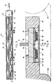
- Figure 8 shows details of the geometry defined by the chips 36 and the rest of the scanner 20 that is useful for a further understanding of the construction of the scanner 20.
- the distance 100 is from the photodiodes 92 within chip 36 and paper 102 being scanned with a scanner 20 incorporating the chip 36.
- the distance 104 is from each photodiode 92 to its corresponding aperture 105.
- Edge 106 representing the bottom of the collimating fiber optic plate 68 is positioned over the chip 36 above the photodiodes 92.
- Points 108 represent the crossover points of each image passing through the aperture defined by each optical fiber.
- Distance 110 is from each detector 92 to its corresponding crossover point 108.
- Distance 112 is the width of the detection area of each photodiode 92 on the paper 102.
- An analog/digital converter could also be provided to receive the outputs, in order to supply signals representing grey tones scanned by the device 20.
- Shaped output pulses are supplied on line 148 to data gate 124.
- Data gate 124 supplies its outputs on lines 150 to an I/O interface circuit 152.
- the data stream is supplied on line 154 to a parallel or serial port of a computer to which the scanner is connected.
Landscapes
- Physics & Mathematics (AREA)
- Engineering & Computer Science (AREA)
- Electromagnetism (AREA)
- General Physics & Mathematics (AREA)
- Toxicology (AREA)
- General Health & Medical Sciences (AREA)
- Artificial Intelligence (AREA)
- Computer Vision & Pattern Recognition (AREA)
- Health & Medical Sciences (AREA)
- Theoretical Computer Science (AREA)
- Facsimile Scanning Arrangements (AREA)
- Eye Examination Apparatus (AREA)
- Image Input (AREA)
- Mechanical Optical Scanning Systems (AREA)
- Switches Operated By Changes In Physical Conditions (AREA)
- Measurement And Recording Of Electrical Phenomena And Electrical Characteristics Of The Living Body (AREA)
Claims (9)
- Handgehaltene Abtastvorrichtung (20) für Text und Graphik- mit einem langgestreckten Gehäuse (22),- mit einer linienförmigen Öffnung (27), die sich längs des Gehäuses (22) erstreckt,- mit einer linearen Reihe (34) aus lichtempfindlichen Elementen (36) hinter und parallel zur linienförmigen Öffnung (27),- mit einer linienförmigen Lichtquelle (30), die parallel zu und im Abstand von der Reihe (34) aus lichtempfindlichen Elementen angeordnet ist, wobei die Lichtquelle (30) so positioniert ist, daß sie Licht durch die linienförmige Öffnung (27) auf ein Blatt richtet, das von der Vorrichtung (20) abzutastende Informationen aufweist, und- mit einer Einrichtung (28) zum Aufrechterhalten der Bewegungsrichtung, die auf dem Gehäuse (22) angebracht ist und beim Gebrauch der Vorrichtung bewirkt, eine Bewegungsrichtung des Gehäuses (22) über ein Blatt, das von der Vorrichtung (20) abzutastende Informationen aufweist, aufrechtzuerhalten,dadurch gekennzeichnet,- daß die Einrichtung zum Aufrechterhalten der Bewegungsrichtung eine Walze aus einem Material (28) mit hoher Reibung aufweist, die sich im wesentlichen über die Länge der linienförmigen Öffnung (27) erstreckt, und- daß die lineare Reihe (34) eine als integrierte Schaltung ausgebildete Reihe aus lichtempfindlichen Elementen (92) ist.
- Vorrichtung nach Anspruch 1, dadurch gekennzeichnet,- daß die Reihe (34) aus lichtempfindlichen Elementen eine Vielzahl von integrierten Schaltungen (36) aus lichtempfindlichen Elementen aufweist,- daß ein transparenter Materialkörper (66) über jeder integrierten Schaltung (36) positioniert ist, und- daß eine kollimierende faseroptische Platte (68) auf dem transparenten Materialkörper (66) über den lichtempfindlichen Elementen jeder integrierten Schaltung (36) positioniert ist.
- Vorrichtung nach Anspruch 1 oder Anspruch 2, dadurch gekennzeichnet, daß die linienförmige Lichtquelle eine lineare Reihe (30) aus lichtemittierenden Dioden (32) ist.
- Vorrichtung nach Anspruch 3, dadurch gekennzeichnet, daß die Reihe (34) aus lichtempfindlichen Elementen eine Vielzahl von integrierten Schaltungen (36) aus lichtempfindlichen Elementen aufweist, die auf beiden Seiten der Reihe (30) aus lichtemittierenden Dioden angebracht und so angeordnet sind, daß sich in Richtung der zwei Reihen (34, 30) zwischen einem letzten lichtempfindlichen Element in einer der Schaltungen (36) und einem ersten lichtempfindlichen Element in der nächsten integrierten Schaltung auf der anderen Seite der Reihe (30) aus lichtemittierenden Dioden kein Spalt befindet.
- Vorrichtung nach Anspruch 4 oder Anspruch 3, dadurch gekennzeichnet, daß die Vielzahl integrierter Schaltungen (36) und die lineare Reihe (30) aus lichtemittierenden Dioden (32) auf einem gemeinsamen Substrat (60) angebracht sind, wobei das Substrat (60) hinter der linienförmigen Öffnung (27) positioniert ist und ein transparentes Fenster (27) aufweist, das in der linienförmigen Öffnung (27) über der Vielzahl integrierter Schaltungen (36) und der Reihe (30) aus lichtemittierenden Dioden angebracht ist.
- Vorrichtung nach einem vorhergehenden Anspruch, gekennzeichnet durch eine Einrichtung (84) zur Bestimmung des Ausmaßes der Abtastbewegung der Vorrichtung (20), wobei die Einrichtung (84) zur Bewegungsbestimmung so angeschlossen ist, daß sie Signale zur Steuerung des Betriebs der linearen Reihe (34) aus lichtempfindlichen Elementen liefert, um eine Vielzahl von Abtastzeilen zu bilden, während die Vorrichtung (20) über ein abzutastende Informationen enthaltendes Blatt bewegt wird.
- Vorrichtung nach Anspruch 6, dadurch gekennzeichnet, daß die Einrichtung (84) zur Bewegungsbestimmung so angeschlossen ist, daß sie den Betrieb der Lichtquelle (30) steuert, um eine gleichförmige Beleuchtungsmenge für jede Abtastzeile der Vorrichtung (20) zu liefern.
- Vorrichtung nach Anspruch 6 oder Anspruch 7, dadurch gekennzeichnet, daß die Einrichtung (84) zur Bewegungsbestimmung ein bewegliches Teil (82), das ein Muster aus hellen und dunklen Bereichen enthält, wobei das bewegliche Teil so positioniert ist, daß es von der Walze (28) bewegt wird, und eine Codiereinrichtung aufweist, die so positioniert ist, daß sie das Muster aus hellen und dunklen Bereichen auf dem beweglichen Teil (82) erfaßt.
- Vorrichtung nach Anspruch 8, gekennzeichnet durch zwei Einrichtungen (84) zur Bewegungsbestimmung, die an entgegengesetzten Enden der Walze (28) angebracht sind.
Priority Applications (1)
| Application Number | Priority Date | Filing Date | Title |
|---|---|---|---|
| AT85304963T ATE77889T1 (de) | 1984-07-13 | 1985-07-11 | Handgefuehrte abtastvorrichtung. |
Applications Claiming Priority (2)
| Application Number | Priority Date | Filing Date | Title |
|---|---|---|---|
| US06/630,884 US4707747A (en) | 1984-07-13 | 1984-07-13 | Hand held scanning input device and system |
| US630884 | 1984-07-13 |
Publications (3)
| Publication Number | Publication Date |
|---|---|
| EP0171925A2 EP0171925A2 (de) | 1986-02-19 |
| EP0171925A3 EP0171925A3 (en) | 1986-07-02 |
| EP0171925B1 true EP0171925B1 (de) | 1992-07-01 |
Family
ID=24528955
Family Applications (1)
| Application Number | Title | Priority Date | Filing Date |
|---|---|---|---|
| EP85304963A Expired EP0171925B1 (de) | 1984-07-13 | 1985-07-11 | Handgeführte Abtastvorrichtung |
Country Status (5)
| Country | Link |
|---|---|
| US (1) | US4707747A (de) |
| EP (1) | EP0171925B1 (de) |
| JP (1) | JPS6139674A (de) |
| AT (1) | ATE77889T1 (de) |
| DE (1) | DE3586271T2 (de) |
Families Citing this family (32)
| Publication number | Priority date | Publication date | Assignee | Title |
|---|---|---|---|---|
| JPS6071275A (ja) * | 1983-09-28 | 1985-04-23 | Toshiba Corp | 画像出力装置 |
| US4885640A (en) * | 1986-11-07 | 1989-12-05 | Sharp Kabushiki Kaisha | Image reading apparatus |
| US4792859A (en) * | 1987-02-09 | 1988-12-20 | Ovonic Imaging Systems, Inc. | Digitizing wand adapted for manual and automatic operation |
| US4805032A (en) * | 1987-04-20 | 1989-02-14 | Ricoh Company, Ltd. | Total contact type photoelectric conversion device and optical reader using the same |
| JP2664151B2 (ja) * | 1987-05-25 | 1997-10-15 | 株式会社日立製作所 | 文書編集装置 |
| JPS6410775A (en) * | 1987-07-02 | 1989-01-13 | Tokyo Electric Co Ltd | Original reader |
| CA1301912C (en) * | 1987-07-08 | 1992-05-26 | Toshio Ishikawa | Image input device |
| JP2553871B2 (ja) * | 1987-07-17 | 1996-11-13 | ニスカ株式会社 | 画像入力装置 |
| JPH0448051Y2 (de) * | 1987-09-11 | 1992-11-12 | ||
| JPH0626411B2 (ja) * | 1988-05-19 | 1994-04-06 | ニスカ株式会社 | 画像読取装置のインターフェース回路 |
| US4864411A (en) * | 1988-06-06 | 1989-09-05 | Ncr Corporation | Electronic copy board system |
| JPH0787503B2 (ja) * | 1988-09-13 | 1995-09-20 | シャープ株式会社 | 画像読取装置を有する通信装置 |
| JPH02274158A (ja) * | 1989-04-17 | 1990-11-08 | Omron Corp | イメージ・スキャナ |
| US5239759A (en) * | 1989-04-28 | 1993-08-31 | Dudek Raymond A | Image scanner guide |
| US5140442A (en) * | 1989-08-18 | 1992-08-18 | Mita Industrial Co., Ltd. | Image forming apparatus having an additional data recording means |
| US5355146A (en) * | 1990-03-05 | 1994-10-11 | Bmc Micro-Industries Ltd. | Multi-directional hand scanner and mouse |
| US5040074A (en) * | 1990-05-02 | 1991-08-13 | Xerox Corporation | Full-width simultaneous read/write copier |
| US5162916A (en) * | 1990-07-02 | 1992-11-10 | Xerox Corporation | Compact read/write scanner |
| US5402251A (en) * | 1991-07-26 | 1995-03-28 | Kabushiki Kaisha Toshiba | Image reading apparatus with separated scanner |
| US5250804A (en) * | 1992-09-10 | 1993-10-05 | Ultima Electronic Corp. | Lost scan line detecting method and device for a handheld scanner having a lost line counter |
| AT399059B (de) * | 1992-12-03 | 1995-03-27 | Tabarelli Werner | Bildwandlungseinrichtung |
| US5475503A (en) * | 1994-02-08 | 1995-12-12 | Logitech, Inc. | Roller for optical scanner |
| US5933550A (en) | 1994-10-27 | 1999-08-03 | Nec Corporation | Data inputting device |
| IL118914A0 (en) * | 1996-07-22 | 1996-10-31 | Zohar Argamanit Ltd | Hand-holdable optical scanner particularly useful as electronic translator |
| US6076731A (en) * | 1997-04-10 | 2000-06-20 | Intermec Ip Corp. | Magnetic stripe reader with signature scanner |
| US6299329B1 (en) | 1999-02-23 | 2001-10-09 | Hewlett-Packard Company | Illumination source for a scanner having a plurality of solid state lamps and a related method |
| US6757426B2 (en) * | 2001-03-21 | 2004-06-29 | Eastman Kodak Company | System and method for image processing by automatic color dropout |
| US7416701B2 (en) * | 2001-09-12 | 2008-08-26 | Ecolab Inc. | Calibrator for fluorosensor |
| GB2386017A (en) * | 2002-02-27 | 2003-09-03 | Portable Peripheral Co Ltd | Scanner for personal digital assistant |
| WO2007143047A1 (en) | 2006-06-01 | 2007-12-13 | Ecolab Inc. | Uv fluorometric sensor and method for using the same |
| JP4863840B2 (ja) * | 2006-10-27 | 2012-01-25 | 株式会社リコー | 画素形成装置、光走査装置、光走査方法、画像形成装置、カラー画像形成装置 |
| EP2842306B1 (de) | 2012-04-24 | 2018-07-04 | Hewlett-Packard Development Company, L.P. | Drucksystem und betriebsverfahren |
Family Cites Families (15)
| Publication number | Priority date | Publication date | Assignee | Title |
|---|---|---|---|---|
| US3318996A (en) * | 1963-08-12 | 1967-05-09 | Inst Scient Information | Document copying device having parallel signal transmission parts |
| US3739095A (en) * | 1971-08-02 | 1973-06-12 | Alden Res Found | Scanning apparatus |
| JPS5127675A (ja) * | 1974-09-02 | 1976-03-08 | Tokyo Shibaura Electric Co | Suchiseigyosochi |
| GB1554164A (en) * | 1975-09-11 | 1979-10-17 | Plessey Co Ltd | Optical character recognition systems |
| US4147928A (en) * | 1977-05-02 | 1979-04-03 | Xerox Corporation | Scanning array configuration |
| US4317137A (en) * | 1978-05-17 | 1982-02-23 | Harris Corporation | Optical scan head and printer |
| US4249217A (en) * | 1979-05-29 | 1981-02-03 | International Business Machines Corporation | Separated sensor array abutment |
| JPS5640357A (en) * | 1979-09-11 | 1981-04-16 | Ricoh Co Ltd | Manual subscanning reader |
| JPS5640359A (en) * | 1979-09-11 | 1981-04-16 | Ricoh Co Ltd | Manual subscanning reader |
| JPS5721163A (en) * | 1980-07-14 | 1982-02-03 | Hitachi Ltd | Optical sensor array device |
| JPS5737973A (en) * | 1980-08-13 | 1982-03-02 | Ricoh Co Ltd | Manually operated subscanning type reader |
| US4523235A (en) * | 1982-01-11 | 1985-06-11 | Jan Rajchman | Electronic microcopier apparatus |
| JPS58168379A (ja) * | 1982-03-29 | 1983-10-04 | Toshiba Corp | 画像読取り装置 |
| DE3220016A1 (de) * | 1982-05-27 | 1983-12-01 | Dorner, Jörg, Dr.-Ing., 8000 München | Einrichtung zur herstellung einer optisch bzw. elektronisch oder magnetisch gespeicherten bildinformation einer im wesentlichen flaechigen vorlage |
| US4574317A (en) * | 1983-12-12 | 1986-03-04 | Wayne Scheible | Hand scannable portable copier and method |
-
1984
- 1984-07-13 US US06/630,884 patent/US4707747A/en not_active Expired - Fee Related
-
1985
- 1985-07-11 EP EP85304963A patent/EP0171925B1/de not_active Expired
- 1985-07-11 AT AT85304963T patent/ATE77889T1/de active
- 1985-07-11 DE DE8585304963T patent/DE3586271T2/de not_active Expired - Lifetime
- 1985-07-13 JP JP15501285A patent/JPS6139674A/ja active Pending
Also Published As
| Publication number | Publication date |
|---|---|
| EP0171925A3 (en) | 1986-07-02 |
| ATE77889T1 (de) | 1992-07-15 |
| DE3586271D1 (de) | 1992-08-06 |
| US4707747A (en) | 1987-11-17 |
| EP0171925A2 (de) | 1986-02-19 |
| JPS6139674A (ja) | 1986-02-25 |
| DE3586271T2 (de) | 1992-12-10 |
Similar Documents
| Publication | Publication Date | Title |
|---|---|---|
| EP0171925B1 (de) | Handgeführte Abtastvorrichtung | |
| US5073770A (en) | Brightpen/pad II | |
| US7042490B2 (en) | Image capture module and image capture apparatus for inputting shape of object on three dimensional space | |
| JP3473658B2 (ja) | 指紋読取り装置 | |
| CA2241404A1 (en) | Contact-type image sensor | |
| CA2131465A1 (en) | Integrated solid state light emitting and detecting array and apparatus employing said array | |
| KR20050055606A (ko) | 지문판독장치 및 개인인증시스템 | |
| JPH1065882A (ja) | 媒体表面形状データ取得方法 | |
| US6075240A (en) | Hand-held plastic optical fiber linear scanner for reading color images formed on a surface | |
| US6265706B1 (en) | Edge to edge image sensor and navigator for portable scanner | |
| US6377715B1 (en) | Data inputting device | |
| US4739159A (en) | Optical read out apparatus using a roof mirror lens array | |
| US5121226A (en) | Portable image scanner | |
| EP1079596A2 (de) | Positionserfassungsvorrichtung mit einem einzelligen Photosensor | |
| US4541015A (en) | Two-dimensional image readout device | |
| US4402017A (en) | Optical scanning system utilizing light-emitting diodes | |
| DE60306233D1 (de) | Bildlesesystem | |
| JP2768866B2 (ja) | 密着型イメージセンサ | |
| JP2910600B2 (ja) | 画像入力装置 | |
| EP1133147B1 (de) | Optische Anordnung mit verringerter Breite | |
| EP0435109B1 (de) | Sensoranordnung zum Lesen von gedruckten Markierungen auf einem Aufzeichnungsträger | |
| EP1099934B1 (de) | Positionsmessvorrichtung und -verfahren | |
| USRE36455E (en) | Brightpen/pad II | |
| KR0145335B1 (ko) | 이미지 센서 | |
| JPH083021Y2 (ja) | 密着型画像読取り装置 |
Legal Events
| Date | Code | Title | Description |
|---|---|---|---|
| PUAI | Public reference made under article 153(3) epc to a published international application that has entered the european phase |
Free format text: ORIGINAL CODE: 0009012 |
|
| AK | Designated contracting states |
Designated state(s): AT BE CH DE FR GB IT LI LU NL SE |
|
| PUAL | Search report despatched |
Free format text: ORIGINAL CODE: 0009013 |
|
| AK | Designated contracting states |
Kind code of ref document: A3 Designated state(s): AT BE CH DE FR GB IT LI LU NL SE |
|
| 17P | Request for examination filed |
Effective date: 19861231 |
|
| 17Q | First examination report despatched |
Effective date: 19890320 |
|
| GRAA | (expected) grant |
Free format text: ORIGINAL CODE: 0009210 |
|
| AK | Designated contracting states |
Kind code of ref document: B1 Designated state(s): AT BE CH DE FR GB IT LI LU NL SE |
|
| PG25 | Lapsed in a contracting state [announced via postgrant information from national office to epo] |
Ref country code: SE Effective date: 19920701 Ref country code: NL Effective date: 19920701 Ref country code: LI Effective date: 19920701 Ref country code: CH Effective date: 19920701 Ref country code: BE Effective date: 19920701 Ref country code: AT Effective date: 19920701 |
|
| REF | Corresponds to: |
Ref document number: 77889 Country of ref document: AT Date of ref document: 19920715 Kind code of ref document: T |
|
| ITF | It: translation for a ep patent filed | ||
| REF | Corresponds to: |
Ref document number: 3586271 Country of ref document: DE Date of ref document: 19920806 |
|
| ET | Fr: translation filed | ||
| REG | Reference to a national code |
Ref country code: CH Ref legal event code: PL |
|
| NLV1 | Nl: lapsed or annulled due to failure to fulfill the requirements of art. 29p and 29m of the patents act | ||
| PLBI | Opposition filed |
Free format text: ORIGINAL CODE: 0009260 |
|
| 26 | Opposition filed |
Opponent name: ROCKWELL III, MARSHAL A. Effective date: 19930331 |
|
| PGFP | Annual fee paid to national office [announced via postgrant information from national office to epo] |
Ref country code: LU Payment date: 19940731 Year of fee payment: 10 |
|
| EPTA | Lu: last paid annual fee | ||
| PG25 | Lapsed in a contracting state [announced via postgrant information from national office to epo] |
Ref country code: LU Free format text: LAPSE BECAUSE OF NON-PAYMENT OF DUE FEES Effective date: 19950711 |
|
| PGFP | Annual fee paid to national office [announced via postgrant information from national office to epo] |
Ref country code: DE Payment date: 19960920 Year of fee payment: 12 |
|
| RDAH | Patent revoked |
Free format text: ORIGINAL CODE: EPIDOS REVO |
|
| PGFP | Annual fee paid to national office [announced via postgrant information from national office to epo] |
Ref country code: GB Payment date: 19970702 Year of fee payment: 13 |
|
| PGFP | Annual fee paid to national office [announced via postgrant information from national office to epo] |
Ref country code: FR Payment date: 19970725 Year of fee payment: 13 |
|
| RDAG | Patent revoked |
Free format text: ORIGINAL CODE: 0009271 |
|
| STAA | Information on the status of an ep patent application or granted ep patent |
Free format text: STATUS: PATENT REVOKED |
|
| 27W | Patent revoked |
Effective date: 19970526 |
|
| GBPR | Gb: patent revoked under art. 102 of the ep convention designating the uk as contracting state |
Free format text: 970526 |